length RAM CHASSIS CAB 2023 Owners Manual
[x] Cancel search | Manufacturer: RAM, Model Year: 2023, Model line: CHASSIS CAB, Model: RAM CHASSIS CAB 2023Pages: 444, PDF Size: 20.51 MB
Page 55 of 444
GETTING TO KNOW YOUR VEHICLE53
DIRECTIONAL LED HEADLAMP SYSTEM —
I
F EQUIPPED
This is a system consisting of LED (low/high beam)
headlights that incorporate dynamic cornering with
5-degree inboard/15-degree outboard swivel. The
headlights continuously and automatically adapt
to the driving conditions around bends or when
cornering based on steering wheel angle.
The system directs the headlights to light up the
road in the best way, taking into account the speed
of the vehicle and the bend or corner angle, as well
as the speed of the vehicle while the steering
wheel is being turned.
The adaptive lights are automatically activated
when the vehicle is traveling above approximately
5 mph (8 km/h).
This system can be turned on/off through the
Uconnect Settings under “Steering Directed
Lights” Ú page 199.
PARKING LIGHTS
To turn on the parking lights and instrument panel
lights, rotate the headlight switch clockwise. To
turn off the parking lights, rotate the headlight
switch back to the O (off) position.
NOTE:Vehicles sold in Canada are equipped with a head -
light switch with an AUTO and ON detent but without an OFF detent. Headlights will be deacti-
vated when the headlight switch is placed in the
parking lights position. However, the Daytime
Running Lights (DRLs) will be activated along with
the front and rear marker lights. The DRLs may be
deactivated when the parking brake is engaged.
HEADLIGHTS ON WITH WIPERS
If your vehicle is equipped with Automatic
Headlights, it also has this
customer-programmable feature. When your
headlights are in the automatic mode and the
engine is running, they will automatically turn on
when the wiper system is on. This feature is
programmable through the Uconnect system
Ú
page 199.
If your vehicle is equipped with the Rain Sensing
Wiper system Ú page 58, and it is activated, the
headlights will automatically turn on after the
wipers complete five wipe cycles within
approximately one minute. They will turn off
approximately four minutes after the wipers
completely stop.
NOTE:When your headlights come on during the daytime,
the instrument panel lights will automatically dim
to the lower nighttime intensity.
HEADLIGHT ILLUMINATION ON
A
PPROACH
When enabled, the headlights, exterior door
handle pocket lights (if equipped), and interior
lights will illuminate when the unlock button on the
key fob is pushed as the operator is approaching
the vehicle. This feature can be turned on/off, and
the length of time the headlights stay on can be
programmed for up to 90 seconds within Uconnect
Settings Ú page 199.
HEADLIGHT DELAY
To assist when exiting the vehicle, the headlight
delay feature will leave the headlights on for up to
90 seconds. This delay is initiated when the
ignition is placed in the OFF position while the
headlight switch is on, and then the headlight
switch is cycled off. Headlight delay can be
canceled by either turning the headlight switch on
then off, or by placing the ignition in the ON
position.
NOTE:
This feature can be programmed through the
Uconnect system Ú page 199.
The headlight delay feature is automatically
activated if the headlight switch is left in the
AUTO position when the ignition is placed in the
OFF position.
2
23_DPF_OM_EN_USC_t.book Page 53
Page 70 of 444

68GETTING TO KNOW YOUR VEHICLE
Overhead Sunglass Storage
At the front of the overhead console, a
compartment is provided for the storage of one
pair of sunglasses.
From the closed position, push the door latch to
open the compartment.
Overhead Sunglass Door
The door will slowly rotate to the full open position.
Front Bench Seat Storage — If Equipped
If your vehicle is equipped with a front bench seat,
storage can be found by folding down the center
seatback. A console storage area and cupholders
are available. With the seatback in the upright
position, lifting the seat bottom also reveals a
storage location.
Front Bench Seat Storage Location
Seatback Storage — If Equipped
Located in the back of both the driver and
passenger front seats are pockets that can be
used for storage.
Driver’s Side Seatback Storage
Storage Bin (Regular Cab)
The storage bin is located behind the front seats
and runs the length of the cab.
Storage Bin
Fold Flat Load Floor — If Equipped
Crew Cab models with a 60/40 rear seat may be
equipped with a folding load floor.
WARNING!
Do not operate the vehicle with loose items
stored on the load floor. While driving or in an
accident you may experience abrupt stopping,
rapid acceleration, or sharp turns. Loose objects
stored on the load floor may move around with
force and strike occupants, resulting in serious
or fatal injury.
23_DPF_OM_EN_USC_t.book Page 68
Page 74 of 444
72GETTING TO KNOW YOUR VEHICLE
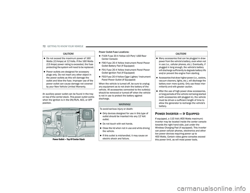
An auxiliary power outlet can be found in the tray
on top of the center stack. This power outlet works
when the ignition is in the ON/RUN, ACC, or OFF
position.
Power Outlet — Top Of Center Stack
Power Outlet Fuse Locations:
F104 Fuse 20 A Yellow UCI Port/ USB Rear
Center Console
F90 Fuse 20 A Yellow Instrument Panel Power
Outlet Battery Fed (If Equipped)
F91 Fuse 20 A Yellow Instrument Panel Power
Outlet Ignition Fed (If Equipped)
F93 Fuse 20 A Yellow Cigar Lighter/ Instrument
Panel Power Outlet (If Equipped)
When the vehicle is turned off, be sure to unplug
any equipment as to not drain the battery of the
vehicle. All accessories connected to the outlet(s)
should be removed or turned off when the vehicle
is not in use to protect the battery against
discharge.
POWER INVERTER — IF EQUIPPED
If equipped, a 115 Volt (400 Watts maximum)
inverter may be located inside the center console
towards the right hand side, just under the
Wireless Charging Pad (if equipped). This inverter
can power cellular phones, electronics and other
low power devices requiring power up to
400 Watts. Certain video game consoles exceed
this power limit, as will most power tools.
CAUTION!
Do not exceed the maximum power of 160
Watts (13 Amps) at 12 Volts. If the 160 Watts
(13 Amps) power rating is exceeded, the fuse
protecting the system will need to be replaced.
Power outlets are designed for accessory
plugs only. Do not insert any other object in
the power outlets as this will damage the
outlet and blow the fuse. Improper use of the
power outlet can cause damage not covered
by your New Vehicle Limited Warranty.
WARNING!
To avoid serious injury or death:
Only devices designed for use in this type of
outlet should be inserted into any 12 Volt
outlet.
Do not touch with wet hands.
Close the lid when not in use and while driving
the vehicle.
If this outlet is mishandled, it may cause an
electric shock and failure.
CAUTION!
Many accessories that can be plugged in draw
power from the vehicle's battery, even when not
in use (i.e., cellular phones, etc.). Eventually, if
plugged in long enough, the vehicle's battery
will discharge sufficiently to degrade battery life
and/or prevent the engine from starting.
Accessories that draw higher power (i.e., coolers,
vacuum cleaners, lights, etc.), will discharge the
battery even more quickly. Only use these inter -
mittently and with greater caution.
After the use of high power draw accessories,
or long periods of the vehicle not being started
(with accessories still plugged in), the vehicle
must be driven a sufficient length of time to
allow the generator to recharge the vehicle's
battery.
23_DPF_OM_EN_USC_t.book Page 72
Page 102 of 444
100GETTING TO KNOW YOUR INSTRUMENT PANEL
Engine Power Reduced Up To 2 Min (Minutes)
During Warm-up — This message will display
during start-up when the ambient temperature
is -25°F (-32°C) and below.
Your vehicle is equipped with an engine warm
up protection feature that may limit engine
performance after cold starting at low ambient
temperatures. The length of time engine speed
is limited is dependent upon engine coolant
temperature. Engine speed may be briefly
limited to 1,000 RPM after starting with coolant
temperature below freezing conditions, and
may be limited to 1,000 RPM for up to approxi -
mately two minutes under more severe cold
conditions.
Coolant Low — This telltale will turn on to indi -
cate the vehicle coolant level is low
Ú page 353.
Diesel Exhaust Fluid (DEF) Warning
Messages
There are four different messages which are
displayed if the vehicle detects that the DEF
system has been filled with a fluid other than DEF,
has experienced component failures, or when
tampering has been detected. The vehicle may be
limited to a maximum speed of 5 mph (8 km/h) if
the DEF system is not serviced within less than
200 miles (322 km) of the fault being detected. When the DEF system needs to be serviced the
following warnings will display:
DEF Low Refill Soon
— This message will display
when the low level is reached, during vehicle start
up, and with increased frequency during vehicle
operation. It will be accompanied by a single
chime. Approximately 5 gallons (19 Liters) of DEF
is required to refill the tank when this message is
initially displayed on pickup applications, and
approximately 7 gallons (26 Liters) are required
on chassis-cab applications.
Speed Limited to 5 MPH in XXX mi Refill DEF —
This message will continuously display if the
“DEF Low Refill Soon” message is ignored, and
the frequency of occurrence of the chime will
increase unless up to 2 gallons (7.5 Liters) of
DEF is added to the tank.
5 MPH Max Speed on Restart, Long Idle or
Refuel Refill DEF — This message will continu -
ously display when the counter reaches zero,
and will be accompanied by a periodic chime.
The vehicle will only be capable of a maximum
speed of 5 mph upon the first of the following
conditions to occur:
If the vehicle is shutoff and restarted.
If the vehicle is idled for an extended period
of time, approximately one hour or greater.
If the system detects that the level of fuel in
the tank has increased. Add a minimum of 2 gallons (7.5 Liters) of DEF
to the tank in order to avoid vehicle operation at
a maximum speed of 5 mph (8 km/h).
NOTE:A minimum of 2 gallons (7.5 Liters) may be
required to restore normal vehicle operation.
Although the vehicle will start normally and can be
placed in gear after this message has been initially
displayed, extreme caution should be utilized since
the vehicle will only be capable of maneuvering at
a maximum speed of 5 mph (8 km/h).
Diesel Exhaust Fluid (DEF) Fault Warning
Messages
There are five different messages which are
displayed if the vehicle detects that the DEF
system has been filled with a fluid other than DEF,
has experienced component failures, or when
tampering has been detected. The vehicle may be
limited to a maximum speed of 5 mph (8 km/h) if
the DEF system is not serviced within less than
200 miles (322 km) of the fault being detected.
When the DEF system needs to be serviced the
following warnings will display:
Service DEF System See Dealer — This message
will display when the fault is initially detected,
each time the vehicle is started, and periodically
during driving. The message will be accompa -
nied by a single chime. We recommend you
23_DPF_OM_EN_USC_t.book Page 100
Page 121 of 444

STARTING AND OPERATING119
3. While the Wait To Start Indicator Light is on, the instrument cluster will additionally display
a gauge or bar whose initial length represents
the full "Wait to Start" time period. Its length
will decrease until it disappears when the
"Wait to Start" time has elapsed.
4. After the engine Wait To Start Indicator Light goes off, the engine will automatically crank.
5. After engine start-up, check to see that there is oil pressure.
6. Release the parking brake and drive.
NOTE:
Engine idle speed will automatically increase to
1,000 RPM and engage the Variable Geometry
Turbocharger at low coolant temperatures to
improve engine warm-up.
The engine will not automatically crank after the
engine Wait To Start Indicator Light goes off if a
door or the hood is ajar.
If the engine stalls, or if the ignition switch is left
ON for more than two minutes after the Wait To
Start Indicator Light goes out, reset the intake
air heater by turning the ignition switch to the
OFF position for at least 5 seconds and then
back ON. Repeat steps 1 through 6 of “Keyless
Enter ‘n Go™ Starting Procedure – Engine Mani -
fold Air Temperature 0°F To 66°F (–18°C to
19°C).”
EXTREME COLD WEATHER
The Cummins® Turbo Diesel engine is equipped
with several features designed to assist cold
weather starting and operation:
The engine block heater is a resistance heater
installed in the water jacket of the engine just
above and behind the oil filter. It requires a
110–115 Volt AC electrical outlet with a
grounded, three-wire extension cord.
NOTE:The engine block heater cord is a factory installed
option. If your vehicle is not equipped, heater cords
are available from an authorized Mopar® dealer.
A 12 Volt heater built into the fuel filter housings
aid in preventing fuel gelling. It is controlled by a
built-in thermostat.
An intake air heater system both improves
engine starting and reduces the amount of
white smoke generated by a warming engine.
NORMAL STARTING PROCEDURE —
E
NGINE MANIFOLD AIR TEMPERATURE
A
BOVE 66°F (19°C)
Observe the instrument panel cluster lights when
starting the engine.
1. Always apply the parking brake.
2. Shift into PARK for an automatic transmission.
3. Place the ignition switch in the ON/RUN
position and watch the instrument panel
cluster lights.
CAUTION!
If the Water in Fuel Indicator Light remains on,
DO NOT START the engine before you drain the
water from the fuel filters to avoid engine
damage Ú page 360.
CAUTION!
Do not crank engine for more than 25 seconds
at a time or starter motor damage may result.
Turn the ignition switch to the OFF position and
wait at least two minutes for the starter to cool
before repeating start procedure.
CAUTION!
If the Water in Fuel Indicator Light remains on,
DO NOT START the engine before you drain the
water from the fuel filters to avoid engine
damage Úpage 360.
4
23_DPF_OM_EN_USC_t.book Page 119
Page 122 of 444

120STARTING AND OPERATING
4. Place the ignition switch in the START position and crank the engine. Do not press the
accelerator during starting.
5. Check that the Oil Pressure Warning Light has turned off.
6. Release the parking brake.
STARTING PROCEDURE — ENGINE
M
ANIFOLD AIR TEMPERATURE 0°F TO
66°F (–18°C
TO 19°C)
NOTE:The temperature displayed in the instrument
cluster does not necessarily reflect the engine
manifold air temperature Ú page 89. When
engine temperatures fall below 66°F (19°C) the
Wait To Start Indicator Light will remain on indi -
cating the intake air heater system is active. Follow the steps in the “Normal Starting”
procedure except:
1. The Wait To Start Indicator Light will remain
on for a period of time that varies depending
on the engine temperature.
2. While the Wait To Start Indicator Light is on, the instrument cluster will additionally display
a gauge or bar whose initial length represents
the full “Wait to Start” time period. Its length
will decrease until it disappears when the
“Wait to Start” time has elapsed.
3. After the Wait To Start Indicator Light goes off, place the ignition switch in the START position.
Do not press the accelerator during starting. 4. After engine start-up, check that the Oil
Pressure Warning Light has turned off.
5. Release the parking brake and drive.
NOTE:
Engine idle speed will automatically increase to
1,000 RPM and engage the Variable Geometry
Turbocharger at low coolant temperatures to
improve engine warm-up.
Automatic equipped vehicles with optional
Keyless Enter ‘n Go™ – If the ENGINE START/
STOP button is pushed once while in PARK with
the ignition off and driver’s foot on the brake
pedal, the vehicle will automatically crank and
start after the “Wait to Start” time has elapsed.
If it is desired to abort the start process before it
completes, the driver’s foot should be fully
removed from the brake pedal prior to pushing
the start button again in order for the ignition to
move directly to off.
If the engine stalls, or if the ignition switch is left
on for more than two minutes after the Wait To
Start Indicator Light goes out, reset the intake
air heater by turning the ignition switch to the
OFF position for at least five seconds and then
back to the ON/RUN position. Repeat steps 1
through 5 of “Starting Procedure – Engine Mani -
fold Air Temperature 0°F To 66°F (–18°C to
19°C).”
CAUTION!
Do not crank engine for more than 25 seconds
at a time or starter motor damage may result.
Turn the ignition switch to the OFF position and
wait at least two minutes for the starter to cool
before repeating start procedure.
CAUTION!
If the Water in Fuel Indicator Light remains on,
DO NOT START the engine before you drain the
water from the fuel filters to avoid engine
damage Ú page 360.
CAUTION!
Do not crank engine for more than 25 seconds
at a time or starter motor damage may result.
Turn the ignition switch to the OFF position and
wait at least two minutes for the starter to cool
before repeating start procedure.
23_DPF_OM_EN_USC_t.book Page 120
Page 124 of 444

122STARTING AND OPERATING
NORMAL OPERATION — DIESEL ENGINE
Observe the following when the engine is
operating.
All message center lights are off.
Malfunction Indicator Light (MIL) is off.
Engine oil pressure is above 10 psi (69 kPa) at
idle.
Voltmeter operation: The voltmeter may show a gauge fluctuation at
various engine temperatures. This cycling
operation is caused by the post-heat cycle of the
intake manifold heater system. The number of
cycles and the length of the cycling operation is
controlled by the engine control module. Post-heat
operation can run for several minutes, and then
the electrical system and voltmeter needle will
stabilize.
The cycling action will cause temporary dimming of
the headlamps, interior lamps, and also a
noticeable reduction in blower motor speed.
COLD WEATHER PRECAUTIONS
Operation in ambient temperature below 32°F
(0°C) may require special considerations. The
following charts suggest these options:
Fuel Operating Range
NOTE:Use Ultra Low Sulfur Diesel (ULSD) Fuels
ONLY.
Fuel Operating Range Chart
*Number 1 ULSD Fuel should only be used where
extended arctic conditions (0°F/-18°C) exist.
NOTE:
Use of Climatized ULSD or Number 1 ULSD Fuel
results in a noticeable decrease in fuel
economy.
Climatized ULSD Fuel is a blend of Number 2
ULSD and Number 1 ULSD Fuels which reduces
the temperature at which wax crystals form in
fuel.
Never leave children alone in a vehicle, or with
access to an unlocked vehicle. Allowing chil -
dren to be in a vehicle unattended is
dangerous for a number of reasons. A child or
others could be seriously or fatally injured.
Children should be warned not to touch the
parking brake, brake pedal or the gear
selector. Do not leave the key fob in or near
the vehicle (or in a location accessible to chil -
dren), and do not leave the ignition of a
vehicle equipped with Keyless Enter ‘n Go™ in
the ACC or ON/RUN position. A child could
operate power windows, other controls, or
move the vehicle.
WARNING!
23_DPF_OM_EN_USC_t.book Page 122
Page 125 of 444

STARTING AND OPERATING123
The fuel grade should be clearly marked on the
pump at the fuel station.
The engine requires the use of ULSD Fuel. Use
of incorrect fuel could result in engine and
exhaust system damage Ú page 413.
If climatized or diesel Number 1 ULSD Fuel is
not available, and you are operating below
(20°F/-6°C), in sustained arctic conditions,
Mopar® Premium Diesel Fuel Treatment (or
equivalent) is recommended to avoid gelling
(see Fuel Operating Range Chart).
Under some circumstances increased engine
noise may be audible in the seconds following a
cold start. This is most likely to occur when using
fuel that isn't blended for the ambient tempera -
ture present. This may occur on an unseason -
ably cold day or when a truck is fueled in a
warmer climate and driven to a colder climate.
The noise can typically be prevented by using
Mopar® Premium Diesel Fuel Treatment as
recommended (see Fuel Operating Range
Chart).
Engine Oil Usage
For the correct engine oil viscosity Ú page 353.
Winter Front Cover Usage
A Winter front or cold weather cover is to be used
in ambient temperatures below 32°F (0°C),
especially during extended idle conditions. This
cover is equipped with four flaps for managing total grille opening in varying ambient
temperatures. If a Winter front or cold weather
cover is to be used the flaps should be left in the
full open position to allow air flow to the charge air
cooler and automatic transmission oil cooler.
When ambient temperatures drop below 0°F
(-17°C) the four flaps need to be closed. A suitable
cold weather cover is available from a Mopar®
dealer.
Battery Blanket Usage
A battery loses 60% of its cranking power as the
battery temperature decreases to 0°F (-18°C). For
the same decrease in temperature, the engine
requires twice as much power to crank at the same
RPM. The use of 120 Volt AC powered battery
blankets will greatly increase starting capability at
low temperatures. Suitable battery blankets are
available from an authorized Mopar® dealer.
Engine Warm-Up
Avoid full throttle operation when the engine is
cold. When starting a cold engine, bring the engine
up to operating speed slowly to allow the oil
pressure to stabilize as the engine warms up.
NOTE:High-speed, no-load running of a cold engine can
result in excessive white smoke and poor engine
performance. No-load engine speeds should be
kept under 1,000 RPM during the warm-up period,
especially in cold ambient temperature conditions.
Your vehicle is equipped with an engine warm-up
protection feature that may limit engine
performance after cold starting at low ambient
temperatures. The length of time engine speed is
limited is dependent upon engine coolant
temperature. Engine speed may be briefly limited
to 1,000 RPM after starting with coolant
temperature below freezing conditions, and may
be limited to 1,000 RPM for up to approximately
two minutes under more severe cold conditions.
NOTE:If ambient temperatures are low and the coolant
temperature is below 180°F (82°C), the engine
idle speed will slowly increase to 1,000 RPM after
two minutes of idle, if the following conditions are
met:
Foot is off brake pedal and accelerator pedal.
Automatic transmission is in PARK.
Vehicle speed is 0 mph (0 km/h).
Applying the accelerator pedal will cancel fast
idle.
Operating the exhaust brake at idle will greatly
improve warm-up rate and will help keep the
engine close to operating temperature during
extended idle.
4
23_DPF_OM_EN_USC_t.book Page 123
Page 176 of 444
174STARTING AND OPERATING
Inputting Trailer Values
For the Trailer Surround View Camera system to
function, all fields must be entered. When a value
is needed the screen will display “Required”.
When the Trailer Type button is selected two
options are available: Conventional or Gooseneck/
5th Wheel.
Activation
The Trailer Surround Camera can be activated
through the Uconnect system when the vehicle is
in PARK, NEUTRAL, or DRIVE.
When the vehicle is shifted into REVERSE,
Surround View Camera showing the Top View and
Back Up Camera is the default view of the system.
Press the More Cams button and then press the
Trailer tab to access the Trailer Cameras. Press Trailer Surround Camera button to access Top
View and Rear View of the trailer.
If the camera delay is turned on, the camera image
will display for up to 10 seconds after shifting out
of REVERSE. The camera image will not display for
10 seconds if the vehicle speed exceeds 8 mph
(13 km/h), the vehicle is shifted into PARK, or the
ignition is placed in the OFF position. The
touchscreen X button disables the display of the
camera image.
If the camera delay is turned off, the camera image
will close and display the previous screen after
shifting out of REVERSE.
Modes Of Operation
The Trailer Surround View Camera system offers
two different camera displays:
Top View split screen with one selected
mounted camera
Full screen view of a selected mounted camera
Press the More Cams button on the Surround View
screen and select the Trailer tab to access the
Trailer Cameras. Press Trailer Surround Camera
button to access the default Top View and Rear
View of the trailer.
Top View
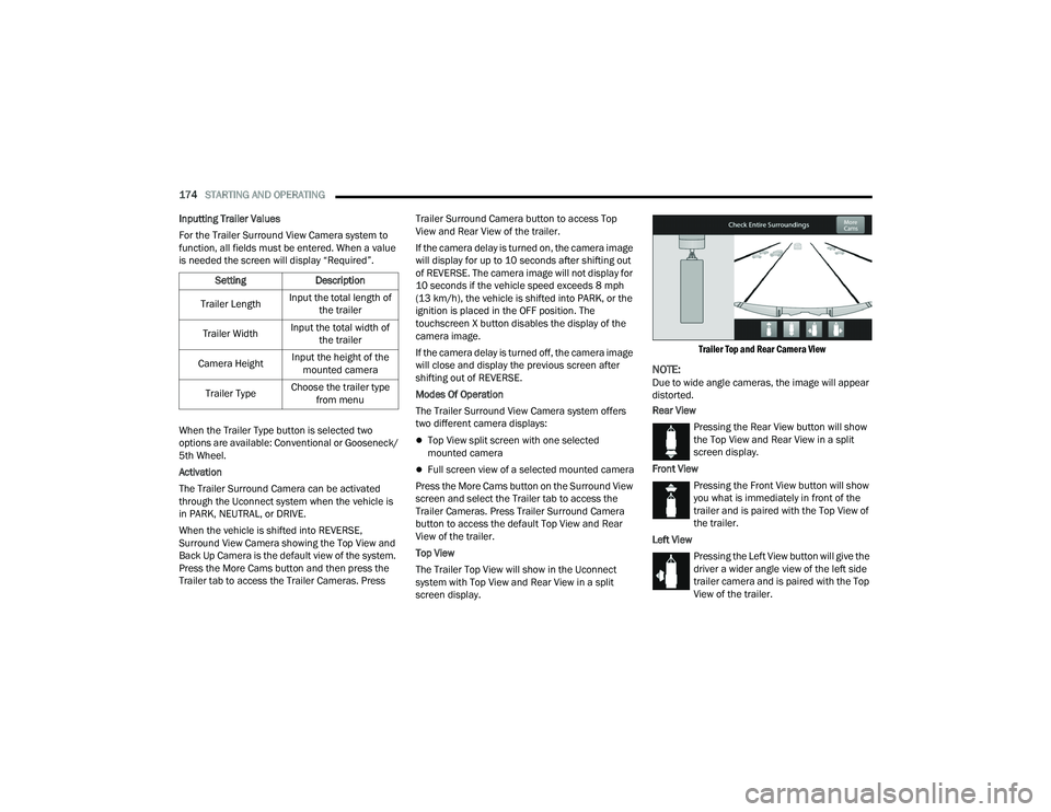
The Trailer Top View will show in the Uconnect
system with Top View and Rear View in a split
screen display.
Trailer Top and Rear Camera View
NOTE:Due to wide angle cameras, the image will appear
distorted.
Rear View
Pressing the Rear View button will show
the Top View and Rear View in a split
screen display.
Front View Pressing the Front View button will show
you what is immediately in front of the
trailer and is paired with the Top View of
the trailer.
Left View Pressing the Left View button will give the
driver a wider angle view of the left side
trailer camera and is paired with the Top
View of the trailer.
Setting
Description
Trailer Length Input the total length of
the trailer
Trailer Width Input the total width of
the trailer
Camera Height Input the height of the
mounted camera
Trailer Type Choose the trailer type
from menu
23_DPF_OM_EN_USC_t.book Page 174
Page 209 of 444
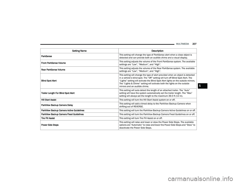
MULTIMEDIA207
ParkSense This setting will change the type of ParkSense alert when a close object is
detected and can provide both an audible chime and a visual display.
Front ParkSense Volume This setting adjusts the volume of the Front ParkSense system. The available
settings are “Low”, “Medium”, and “High”.
Rear ParkSense Volume This setting adjusts the volume of the Rear ParkSense system. The available
settings are “Low”, “Medium”, and “High”.
Blind Spot Alert This setting will change the type of alert provided when an object is detected
in a vehicle’s blind spot. The “Off” setting will turn off Blind Spot Alert. The
“Lights” setting will activate the Blind Spot Alert lights on the outside mirrors.
The “Lights & Chime” setting will activate both the lights on the outside
mirrors and an audible chime.
Trailer Length For Blind Spot Alert This setting will auto detect the length of an attached trailer. The “Auto”
setting will have the system automatically set the trailer length. The “Max”
setting will always set the length to the maximum 39.5 ft (12 m).
Hill Start Assist This setting will turn the Hill Start Assist system on or off.
ParkView Backup Camera Delay This setting will add a timed delay to the ParkView Backup Camera when
shifting out of REVERSE.
ParkView Backup Camera Active Guidelines This setting will turn the ParkView Backup Camera Active Guidelines on or off.
ParkView Backup Camera Fixed Guidelines This setting will turn the ParkView Backup Camera Fixed Guidelines on or off.
Tire Fill Assist This setting will turn Tire Fill Assist on or off.
Power Side Steps This setting will raise and lower or stow the Power Side Steps. The available
options are “Automatic” to raise and lower the Power Side Steps and “Stow” to
deactivate the Power Side Steps.
Setting Name
Description
5
23_DPF_OM_EN_USC_t.book Page 207