panel Ram ProMaster 2014 Owner's Manual
[x] Cancel search | Manufacturer: RAM, Model Year: 2014, Model line: ProMaster, Model: Ram ProMaster 2014Pages: 410, PDF Size: 2.83 MB
Page 354 of 410

•For grease stains, apply MOPAR® Multi-Purpose
Cleaner to a clean, damp cloth and remove stain. Use
a fresh, damp towel to remove soap residue.
• Do not use any harsh solvents or any other form of
protectants on Stain Repel products.
Interior Care
Instrument Panel Surfaces
The instrument panel cover has a low glare surface,
which minimizes reflections in the windshield. Do not
use protectants or other products which may cause
undesirable reflections. Use soap and warm water to
restore the low glare surface.
Cleaning Interior Trim
Interior trim should be cleaned starting with a damp
cloth, a damp cloth with MOPAR® Total Clean or equiva-
lent, then MOPAR® Spot & Stain Remover or equivalent if absolutely necessary. Do not use harsh cleaners or
Armor All®. Use MOPAR® Total Clean or equivalent to
clean vinyl upholstery.
Cleaning Leather Upholstery
MOPAR® Total Clean or equivalent is specifically recom-
mended for leather upholstery.
Your leather upholstery can be best preserved by regular
cleaning with a damp soft cloth. Small particles of dirt
can act as an abrasive and damage the leather upholstery
and should be removed promptly with a damp cloth.
Stubborn soils can be removed easily with a soft cloth
and MOPAR® Total Clean or equivalent. Care should be
taken to avoid soaking your leather upholstery with any
liquid. Please do not use polishes, oils, cleaning fluids,
solvents, detergents, or ammonia-based cleaners to clean
your leather upholstery. Application of a leather condi-
tioner is not required to maintain the original condition.
352 MAINTAINING YOUR VEHICLE
Page 357 of 410
Cleaning The Instrument Panel Cupholders
Removal
Pull the flexible liner from the cupholder drawer starting
at one edge to ease removal.
Cleaning
The liner is top shelf dishwasher safe, or you may follow
the cleaning procedure below.
Soak the liner in a mixture of medium hot tap water and
one teaspoon of mild liquid dish soap. Let soak for
approximately 30 minutes. After 30 minutes, pull the
liner from the water and dip it back into the water about
six times. This will loosen any remaining debris. Rinse
the liner thoroughly under warm running water. Shake
the excess water from the liner and dry the outer surfaces
with a clean soft cloth.
Installation
Place the liner into the cupholder drawer and press the
liner into place so that the retention tabs seat into the
corresponding openings in the drawer.
FUSES
WARNING!
•When replacing a blown fuse, always use an appro-
priate replacement fuse with the same amp rating as
the original fuse. Never replace a fuse with another
fuse of higher amp rating. Never replace a blown
fuse with metal wires or any other material. Failure
to use proper fuses may result in serious personal
injury, fire and/or property damage.
(Continued)
7
MAINTAINING YOUR VEHICLE 355
Page 363 of 410
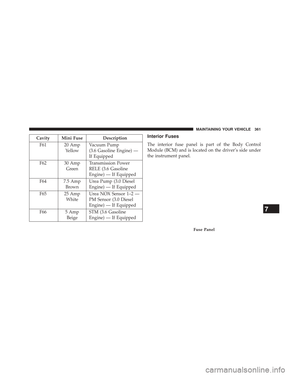
Cavity Mini Fuse DescriptionF61 20 Amp YellowVacuum Pump
(3.6 Gasoline Engine) —
If Equipped
F62 30 Amp GreenTransmission Power
RELE (3.6 Gasoline
Engine) — If Equipped
F64 7.5 Amp BrownUrea Pump (3.0 Diesel
Engine) — If Equipped
F65 25 Amp WhiteUrea NOX Sensor 1–2 —
PM Sensor (3.0 Diesel
Engine) — If Equipped
F66 5 Amp BeigeSTM (3.6 Gasoline
Engine) — If EquippedInterior Fuses
The interior fuse panel is part of the Body Control
Module (BCM) and is located on the driver’s side under
the instrument panel.
Fuse Panel
7
MAINTAINING YOUR VEHICLE 361
Page 364 of 410
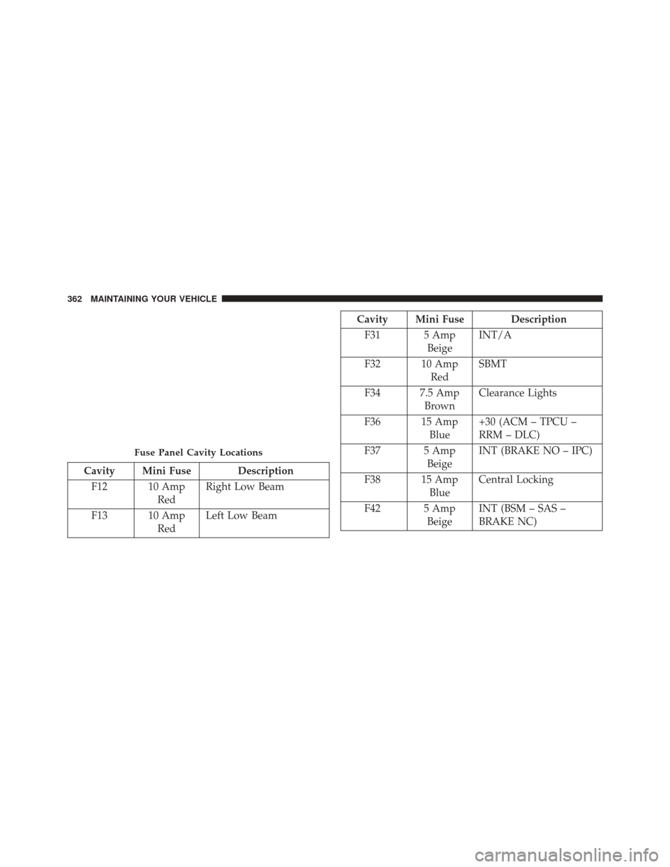
Cavity Mini Fuse DescriptionF12 10 Amp RedRight Low Beam
F13 10 Amp RedLeft Low Beam
Cavity Mini Fuse Description
F31 5 Amp BeigeINT/A
F32 10 Amp RedSBMT
F34 7.5 Amp BrownClearance Lights
F36 15 Amp Blue+30 (ACM – TPCU –
RRM – DLC)
F37 5 Amp BeigeINT (BRAKE NO – IPC)
F38 15 Amp BlueCentral Locking
F42 5 Amp BeigeINT (BSM – SAS –
BRAKE NC)
Fuse Panel Cavity Locations
362 MAINTAINING YOUR VEHICLE
Page 366 of 410
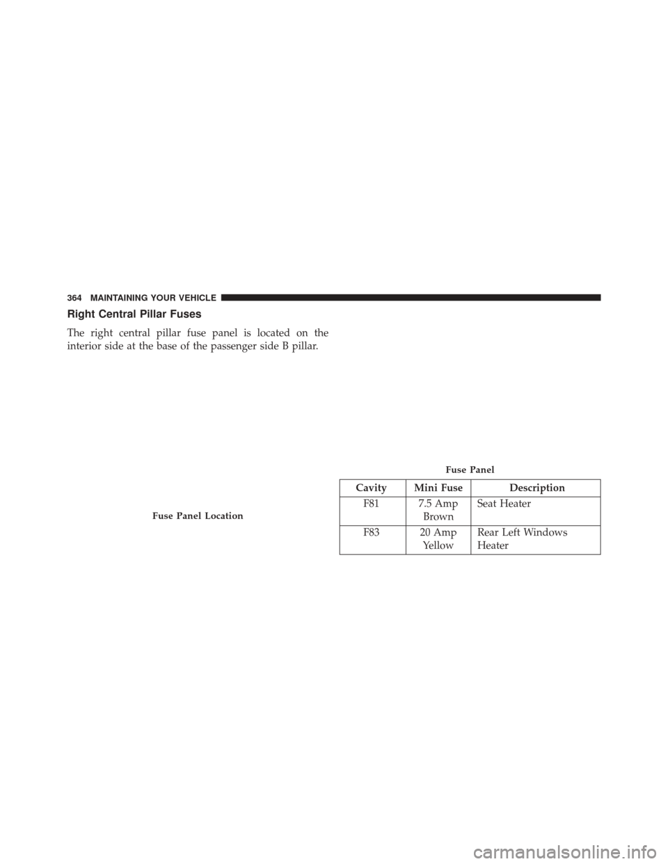
Right Central Pillar Fuses
The right central pillar fuse panel is located on the
interior side at the base of the passenger side B pillar.
Cavity Mini Fuse DescriptionF81 7.5 Amp BrownSeat Heater
F83 20 Amp YellowRear Left Windows
Heater
Fuse Panel Location
Fuse Panel
364 MAINTAINING YOUR VEHICLE
Page 368 of 410

Bulb Number
Front Side Marker Lamps WY5W
Rear Tail/Stop Lamps 7443
Rear Turn Signal Lamps 7440NA
Rear Backup Lamps 921
Rear Side Marker Lamps W3W
Front Fog Lamps H11
License Plate Lamps C5W
Front Roof Lamps WY5W
Rear Roof Lamps W3W
NOTE:
•Numbers refer to commercial bulb types that can
be purchased from your authorized dealer.
•If a bulb needs to be replaced, visit your autho-
rized dealer.
BULB REPLACEMENT
NOTE: Lens fogging can occur under certain atmo-
spheric conditions. This will usually clear as atmospheric
conditions change to allow the condensation to change
back into a vapor. Turning the lamps on will usually
accelerate the clearing process.
Headlamps Low beam and High beam
NOTE: Passenger side headlamp must be removed for
bulb replacement, for driver side headlamp go to step 6
through step 12.
1. Remove screw (1) on lower headlamp filler panel.
2. Remove screws (2) on upper headlamp filler panel.
3. Remove upper screw (1) from headlamp housing.
4. Remove lower screws (2) from headlamp housing.
366 MAINTAINING YOUR VEHICLE
Page 369 of 410

5. Pull Headlamp forward.
6. Remove appropriate plastic cap from the back of theheadlamp housing.
7. Push down on the upper portion of the socket.
8. Pull the socket outward from reflector.
9. Pull bulb outward from socket.
10. Install new bulb.
11. Push socket back into reflector until it locks back into place.
12. Install access cap.
13. Carefully re install headlamp in the same position on the vehicle, so as not to affect headlamp aiming.
14. Install upper screw (1) on headlamp housing. 15. Install lower screws (2) on headlamp housing.
16. Carefully re install screw (1) on lower headlamp filler
panel.
17. Carefully re install screws (2) on upper headlamp filler panel.
Front Turn Signal/Parking Lamps
NOTE: Passenger side headlamp must be removed for
bulb replacement, for driver side headlamp go to step 6
through step 7.
1. Remove screw (1) on lower headlamp filler panel.
2. Remove screws (2) on upper headlamp filler panel.
3. Remove upper screw (1) from headlamp housing.
7
MAINTAINING YOUR VEHICLE 367
Page 370 of 410

4. Remove lower screws (2) from headlamp housing.
5. Pull Headlamp forward.
6. Rotate the bulb counter clockwise and remove.
7. Install the bulb into socket, and rotate bulb/socketclockwise into lamp locking it in place.
8. Carefully re install headlamp in the same position on the vehicle, so as not to affect headlamp aiming.
9. Install upper screw (1) on headlamp housing.
10. Install lower screws (2) on headlamp housing.
11. Carefully re install screw (1) on lower headlamp filler panel.
12. Carefully re install screws (2) on upper headlamp filler panel.Daytime Running Lamp (DRL)/Front Side Marker
Lamp
NOTE: Passenger side headlamp must be removed for
bulb replacement, for driver side headlamp go to step 6
through step 8.
1. Remove screw (1) on lower headlamp filler panel.
2. Remove screws (2) on upper headlamp filler panel.
3. Remove upper screw (1) from headlamp housing.
4. Remove lower screws (2) from headlamp housing.
5. Pull Headlamp forward.
6. Remove the DRL, side marker bulb by pulling straight out.
7. Replace lamp as required and lock in place.
8. Reinstall plastic cap.
368 MAINTAINING YOUR VEHICLE
Page 371 of 410

9. Carefully re install headlamp in the same position onthe vehicle, so as not to affect headlamp aiming.
10. Install upper screw (1) on headlamp housing.
11. Install lower screws (2) on headlamp housing.
12. Carefully re install screw (1) on lower headlamp filler panel.
13. Carefully re install screws (2) on upper headlamp filler panel.
Front Fog Lamps
1. Turn front wheels inboard to access cover in wheelliner.
2. Open the cover on the front of the wheel liner.
3. Remove connection and replace the bulb. 4. Connect the wire and rotate bulb/socket clockwise
into lamp locking it in place.
5. Reinstall the plastic cap and close the cover on the wheel liner.
Front, Rear Roof Lamps
1. Remove two screw and remove the lamp assembly.
2. Remove the socket bulb by turning counterclockwise.
3. Remove bulb and replace as needed.
4. Reinstall the bulb socket and rotate clockwise to lockin place.
5. Reinstall lamp.
7
MAINTAINING YOUR VEHICLE 369
Page 378 of 410
MAINTENANCE SCHEDULE
Your vehicle is equipped with an automatic oil change
indicator system. The oil change indicator system will
remind you that it is time to take your vehicle in for
scheduled maintenance.
Based on engine operation conditions, the oil change
indicator message will illuminate in the instrument clus-
ter. This means that service is required for your vehicle.
Operating conditions such as frequent short-trips, trailer
tow, and extremely hot or cold ambient temperatures
will influence when the “Oil Change Required” message
is displayed. Severe Operating Conditions can cause the
change oil message to illuminate as early as 3,500 miles
(5,600 km) since last reset. Have your vehicle serviced as
soon as possible, within the next 500 miles (805 km).
Your authorized dealer will reset the oil change indicator
message after completing the scheduled oil change. If a
scheduled oil change is performed by someone otherthan your authorized dealer, the message can be reset by
referring to the steps described under “Electronic Vehicle
Information Center (EVIC)” in “Understanding Your
Instrument Panel” for further information.
NOTE:
Under no circumstances should oil change inter-
vals exceed 10,000 miles (16,000 km) or twelve months,
whichever comes first.
Severe Duty All Models
Change Engine Oil at 4,000 miles (6,500 km) if the vehicle
is operated in a dusty and off road environment. This
type of vehicle use is considered Severe Duty.
Once A Month Or Before A Long Trip:
• Check engine oil level
• Check windshield washer fluid level
• Check the tire inflation pressures and look for unusual
wear or damage
8
M A I
N T
E
N
A
N
C E
S
C
H E
D
U L
E
S376 MAINTENANCE SCHEDULES