Ram ProMaster 2018 Owner's Manual
Manufacturer: RAM, Model Year: 2018, Model line: ProMaster, Model: Ram ProMaster 2018Pages: 337, PDF Size: 4.13 MB
Page 181 of 337
HAZARD WARNING FLASHERS
The Hazard Warning flasher switch is located on the
instrument panel below the climate controls.Push the switch to turn on the Hazard Warning
flasher. When the switch is activated, all direc-
tional turn signals will flash on and off to warn
oncoming traffic of an emergency. Push the
switch a second time to turn off the Hazard Warning
flashers. This is an emergency warning system and it should not be
used when the vehicle is in motion. Use it when your
vehicle is disabled and it is creating a safety hazard for
other motorists.
When you must leave the vehicle to seek assistance, the
Hazard Warning flashers will continue to operate even
though the ignition is placed in the OFF position.
NOTE:
With extended use, the Hazard Warning flashers
may wear down your battery.
BULB REPLACEMENT
Replacement Bulbs
Interior Bulbs
Bulb Number
Overhead Lamp C5W
Sun Visors C5W
Courtesy Lamp FF500
Glove Compartment C5W
Rear Courtesy Lamp C5W
7
IN CASE OF EMERGENCY 179
Page 182 of 337

Exterior Bulbs
Bulb Number
Front Low and High Beam Headlamp H7LL
Front Park/Turn Signal Lamps 7444NA
Daytime Running Lamps (If Equipped) 7440
Front Side Marker Lamps WY5W
Rear Tail/Stop Lamps 7443
Rear Turn Signal Lamps 7440NA
Rear Backup Lamps 921
Rear Side Marker Lamps W3W
Front Fog Lamps H11
License Plate Lamps C5W
Front Roof Lamps WY5W
Rear Roof Lamps W3W
NOTE:
•Numbers refer to commercial bulb types that can be purchased from your authorized dealer.
•If a bulb needs to be replaced, visit your authorized dealer.
180 IN CASE OF EMERGENCY
Page 183 of 337

Replacing Exterior Bulbs
Headlamps Low Beam And High beam
NOTE:Passenger side headlamp must be removed for
bulb replacement, for driver side headlamp go to step 6
through step 12.
1. Remove one screw on the lower headlamp filler panel.
2. Remove two screws on the upper headlamp filler panel.
3. Remove one upper screw from the headlamp housing.
4. Remove two lower screws from the headlamp housing.
5. Pull Headlamp forward.
6. Remove appropriate plastic cap from the back of the headlamp housing.
7. Push down on the upper portion of the socket.
8. Pull the socket outward from reflector.
9. Pull bulb outward from socket.
10. Install new bulb.
11. Push socket back into reflector until it locks back into place. 12. Install access cap.
13. Carefully reinstall headlamp in the same position on
the vehicle, so as not to affect headlamp aiming.
14. Install one upper screw on the headlamp housing.
15. Install two lower screws on the headlamp housing.
16. Carefully reinstall one screw on the lower headlamp filler panel.
17. Carefully reinstall two screws on the upper headlamp filler panel.
Front Turn Signal/Parking Lamps
NOTE: Passenger side headlamp must be removed for
bulb replacement, for driver side headlamp go to step 6
through step 7.
1. Remove one screw on the lower headlamp filler panel.
2. Remove two screws on the upper headlamp filler panel.
3. Remove one upper screw from the headlamp housing.
4. Remove two lower screws from the headlamp housing.
5. Pull Headlamp forward.
6. Rotate the bulb counter clockwise and remove.
7
IN CASE OF EMERGENCY 181
Page 184 of 337

7. Install the bulb into socket, and rotate bulb/socketclockwise into lamp locking it in place.
8. Carefully reinstall headlamp in the same position on the vehicle, so as not to affect headlamp aiming.
9. Install the one upper screw on headlamp housing.
10. Install the two lower screws on headlamp housing.
11. Carefully reinstall one screw on the lower headlamp filler panel.
12. Carefully reinstall two screws the on upper headlamp filler panel.
Daytime Running Lamp (DRL)/Front Side Marker
Lamp
NOTE: Passenger side headlamp must be removed for
bulb replacement, for driver side headlamp go to step 6
through step 8.
1. Remove one screw on the lower headlamp filler panel.
2. Remove two screws on the upper headlamp filler panel.
3. Remove one upper screw from the headlamp housing.
4. Remove two lower screws from the headlamp housing. 5. Pull Headlamp forward.
6. Remove the DRL, side marker bulb by pulling straight
out.
7. Replace lamp as required and lock in place.
8. Reinstall plastic cap.
9. Carefully reinstall headlamp in the same position on the vehicle, as not to affect headlamp aiming.
10. Install the one upper screw on the headlamp housing.
11. Install the two lower screws on the headlamp housing.
12. Carefully reinstall one screw on the lower headlamp filler panel.
13. Carefully reinstall two screws on the upper headlamp filler panel.
Front Fog Lamps
1. Turn front wheels inboard to access cover in wheel liner.
2. Open the cover on the front of the wheel liner.
3. Remove connection and replace the bulb.
4. Connect the wire and rotate bulb/socket clockwise intolamp locking it in place.
182 IN CASE OF EMERGENCY
Page 185 of 337
5. Reinstall the plastic cap and close the cover on the wheelliner.
Front, Rear Roof Lamps
1. Remove two screw and remove the lamp assembly.
2. Remove the socket bulb by turning counterclockwise.
3. Remove bulb and replace as needed.
4. Reinstall the bulb socket and rotate clockwise to lock inplace.
5. Reinstall lamp.
Rear Tail, Stop, Backup, Turn Signal And Rear Side
Marker Lamps
1. Open rear doors.
2. Remove the two screws and remove the tail lamp.
3. Remove the tail/stop, turn signal, backup and rear side marker bulb/socket by rotating counter-clockwise.
4. Remove the bulb and replace as needed.
5. Reinstall bulb/socket and rotate clockwise to lock in place.
6. Reinstall lamp.
Replacing Interior Bulbs
Cargo Lamp
1. Using a suitable tool, remove either the lamp above the back door or the sliding door lamp as needed and
disconnect it.
Rear Cargo Lamp Bulb Access
7
IN CASE OF EMERGENCY 183
Page 186 of 337
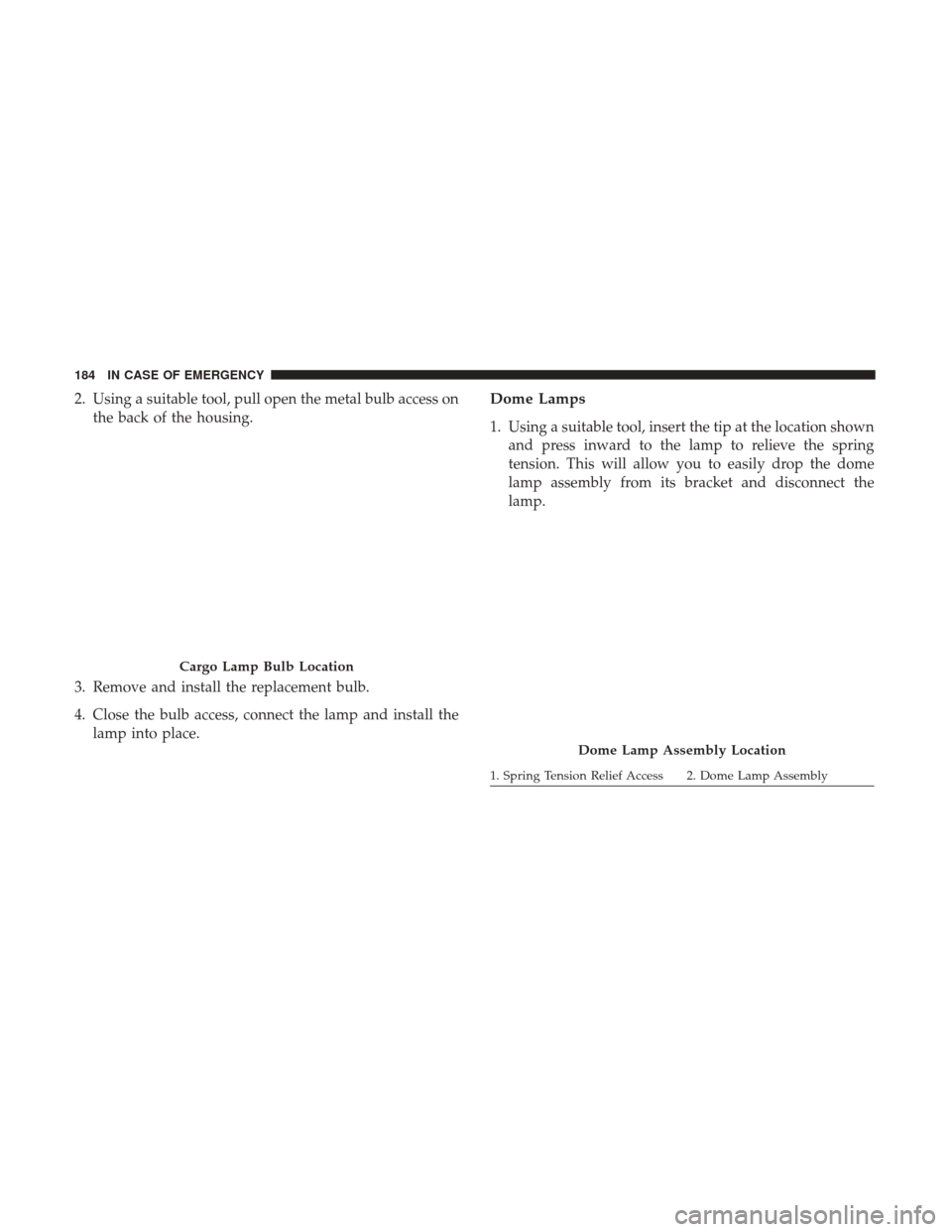
2. Using a suitable tool, pull open the metal bulb access onthe back of the housing.
3. Remove and install the replacement bulb.
4. Close the bulb access, connect the lamp and install the lamp into place.Dome Lamps
1. Using a suitable tool, insert the tip at the location shownand press inward to the lamp to relieve the spring
tension. This will allow you to easily drop the dome
lamp assembly from its bracket and disconnect the
lamp.
Cargo Lamp Bulb Location
Dome Lamp Assembly Location
1. Spring Tension Relief Access 2. Dome Lamp Assembly
184 IN CASE OF EMERGENCY
Page 187 of 337
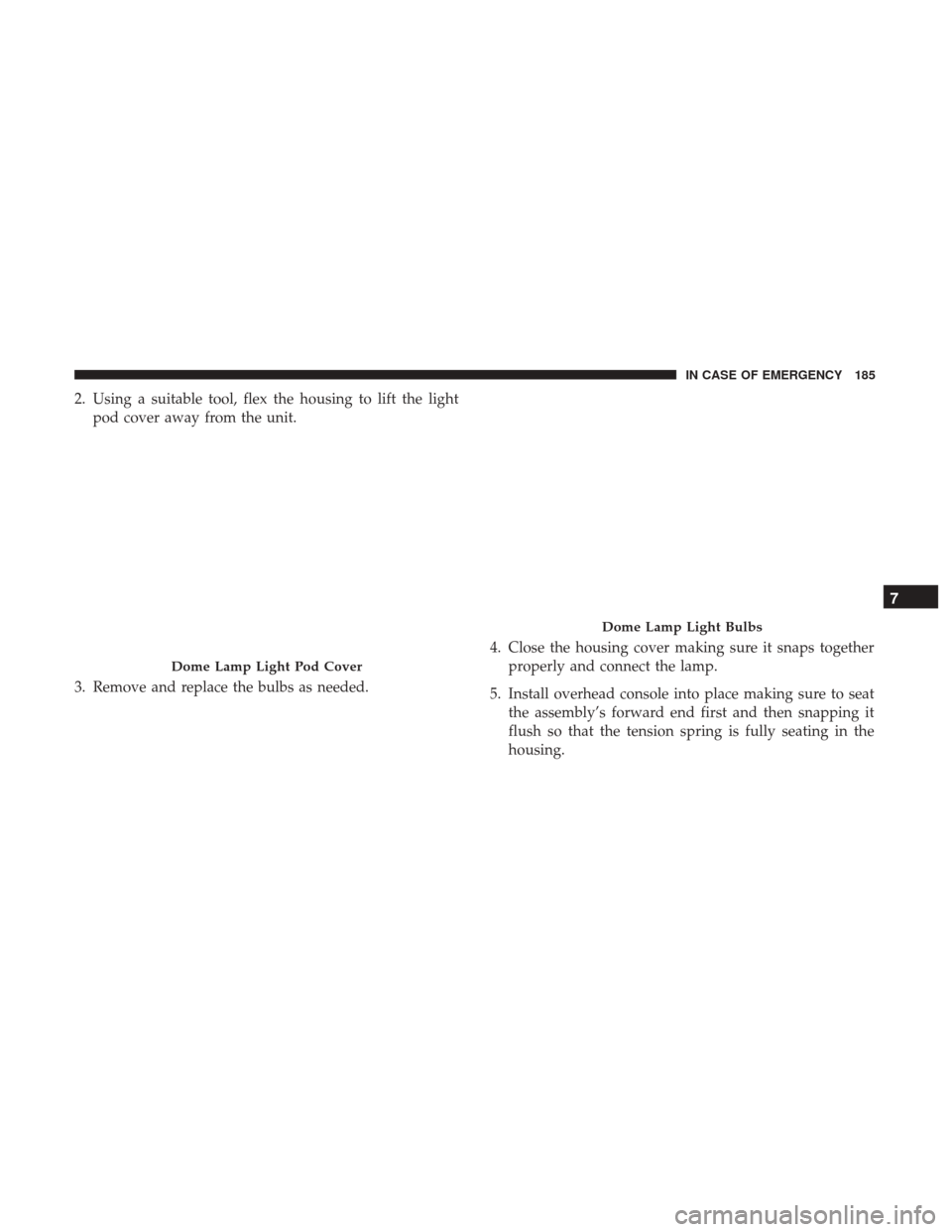
2. Using a suitable tool, flex the housing to lift the lightpod cover away from the unit.
3. Remove and replace the bulbs as needed. 4. Close the housing cover making sure it snaps together
properly and connect the lamp.
5. Install overhead console into place making sure to seat the assembly’s forward end first and then snapping it
flush so that the tension spring is fully seating in the
housing.
Dome Lamp Light Pod Cover
Dome Lamp Light Bulbs
7
IN CASE OF EMERGENCY 185
Page 188 of 337

FUSES
WARNING!
•When replacing a blown fuse, always use an appro-
priate replacement fuse with the same amp rating as
the original fuse. Never replace a fuse with another
fuse of higher amp rating. Never replace a blown
fuse with metal wires or any other material. Do not
place a fuse inside a circuit breaker cavity or vice
versa. Failure to use proper fuses may result in
serious personal injury, fire and/or property damage.
• Before replacing a fuse, make sure that the ignition is
off and that all the other services are switched off
and/or disengaged.
• If the replaced fuse blows again, contact an autho-
rized dealer.
• If a general protection fuse for safety systems (air
bag system, braking system), power unit systems
(engine system, transmission system) or steering
system blows, contact an authorized dealer.
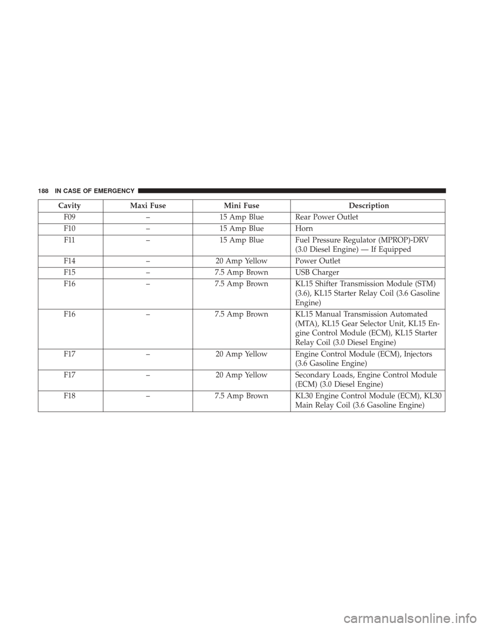
Underhood Fuses
The Front Power Distribution Center is located on the
driver ’s side of the engine compartment. To access the
fuses, remove the cover.
The ID number of the electrical component corresponding
to each fuse can be found on the back of the cover.
Front Power Distribution Center
186 IN CASE OF EMERGENCY
Page 189 of 337

CavityMaxi Fuse Mini Fuse Description
F01 40 Amp Orange –Electronic Stability Control (ESC) Pump
F02 20 Amp Yellow (3.6
Gasoline Engine) –
Starter Relay 3.6L (3.6 Gasoline Engine)
F03 30 Amp Green UREA (3.0 Diesel Engine)
F02 50 Amp Red (3.0 Diesel Engine) –
Glow Plug Unit (3.0 Diesel Engine)
F04 50 Amp Red (3.6 Gaso- line Engine) –
Secondary Power Distribution Center
(PDC) (Trans Power Relay, Vacuum Pump,
KL30 for the Shifter Transmission Module
[STM]) (3.6 Gasoline Engine)
F04 40 Amp Orange (3.0
Diesel Engine) –
Fuel Filter Heater (3.0 Diesel Engine)
F05 30 Amp Green –SELESPEED Pump RELE (3.0 Diesel En-
gine) — If Equipped
F06 40 Amp Orange (non A/C)
60 Amp Blue (A/C) –
Engine Cooling Fan - 2nd Speed
F07 50 Amp Red (non
A/C)
60 Amp Blue (A/C) –
Engine Cooling Fan - 1st Speed
F08 40 Amp Orange –Passenger Compartment Blower
7
IN CASE OF EMERGENCY 187
Page 190 of 337
CavityMaxi Fuse Mini Fuse Description
F09 –15 Amp Blue Rear Power Outlet
F10 –15 Amp Blue Horn
F11 –15 Amp Blue Fuel Pressure Regulator (MPROP)-DRV
(3.0 Diesel Engine) — If Equipped
F14 –20 Amp Yellow Power Outlet
F15 –7.5 Amp Brown USB Charger
F16 –7.5 Amp Brown KL15 Shifter Transmission Module (STM)
(3.6), KL15 Starter Relay Coil (3.6 Gasoline
Engine)
F16 –7.5 Amp Brown KL15 Manual Transmission Automated
(MTA), KL15 Gear Selector Unit, KL15 En-
gine Control Module (ECM), KL15 Starter
Relay Coil (3.0 Diesel Engine)
F17 –20 Amp Yellow Engine Control Module (ECM), Injectors
(3.6 Gasoline Engine)
F17 –20 Amp Yellow Secondary Loads, Engine Control Module
(ECM) (3.0 Diesel Engine)
F18 –7.5 Amp Brown KL30 Engine Control Module (ECM), KL30
Main Relay Coil (3.6 Gasoline Engine)
188 IN CASE OF EMERGENCY