suspension Ram ProMaster 2018 Owner's Manual
[x] Cancel search | Manufacturer: RAM, Model Year: 2018, Model line: ProMaster, Model: Ram ProMaster 2018Pages: 337, PDF Size: 4.13 MB
Page 29 of 337

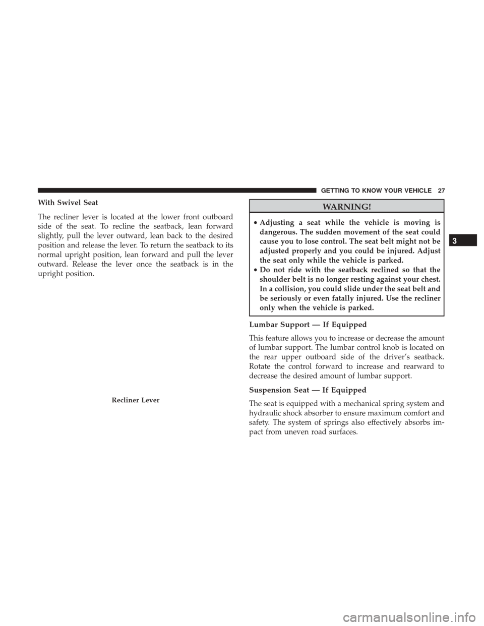
With Swivel Seat
The recliner lever is located at the lower front outboard
side of the seat. To recline the seatback, lean forward
slightly, pull the lever outward, lean back to the desired
position and release the lever. To return the seatback to its
normal upright position, lean forward and pull the lever
outward. Release the lever once the seatback is in the
upright position.WARNING!
•Adjusting a seat while the vehicle is moving is
dangerous. The sudden movement of the seat could
cause you to lose control. The seat belt might not be
adjusted properly and you could be injured. Adjust
the seat only while the vehicle is parked.
• Do not ride with the seatback reclined so that the
shoulder belt is no longer resting against your chest.
In a collision, you could slide under the seat belt and
be seriously or even fatally injured. Use the recliner
only when the vehicle is parked.
Lumbar Support — If Equipped
This feature allows you to increase or decrease the amount
of lumbar support. The lumbar control knob is located on
the rear upper outboard side of the driver’s seatback.
Rotate the control forward to increase and rearward to
decrease the desired amount of lumbar support.
Suspension Seat — If Equipped
The seat is equipped with a mechanical spring system and
hydraulic shock absorber to ensure maximum comfort and
safety. The system of springs also effectively absorbs im-
pact from uneven road surfaces.Recliner Lever
3
GETTING TO KNOW YOUR VEHICLE 27
Page 93 of 337

the intended path, ESC applies the brake of the appropriate
wheel to assist in counteracting the oversteer or understeer
condition.
•Oversteer - when the vehicle is turning more than
appropriate for the steering wheel position.
• Understeer - when the vehicle is turning less than
appropriate for the steering wheel position.
WARNING!
• Electronic Stability Control (ESC) cannot prevent the
natural laws of physics from acting on the vehicle,
nor can it increase the traction afforded by prevailing
road conditions. ESC cannot prevent accidents, in-
cluding those resulting from excessive speed in
turns, driving on very slippery surfaces, or hydro-
planing. ESC also cannot prevent accidents resulting
from loss of vehicle control due to inappropriate
driver input for the conditions. Only a safe, attentive,
and skillful driver can prevent accidents. The capa-
bilities of an ESC equipped vehicle must never be
exploited in a reckless or dangerous manner which
could jeopardize the user ’s safety or the safety of
others.
(Continued)
WARNING! (Continued)
•Vehicle modifications, or failure to properly main-
tain your vehicle, may change the handling charac-
teristics of your vehicle, and may negatively affect
the performance of the ESC system. Changes to the
steering system, suspension, braking system, tire
type and size or wheel size may adversely affect ESC
performance. Improperly inflated and unevenly
worn tires may also degrade ESC performance. Any
vehicle modification or poor vehicle maintenance
that reduces the effectiveness of the ESC system can
increase the risk of loss of vehicle control, vehicle
rollover, personal injury and death.
ESC Operating Modes
The “ESC Off” switch is located in the center
switch bank, next to the hazard flasher switch.
ESC On
This mode is the normal operating mode for ESC equipped
vehicles. Whenever the vehicle is started, the ESC system
5
SAFETY 91
Page 164 of 337

Tire Size
The tire size on the Vehicle Certification Label represents
the actual tire size on your vehicle. Replacement tires must
be equal to the load capacity of this tire size.
Rim Size
This is the rim size that is appropriate for the tire size
listed.
Inflation Pressure
This is the cold tire inflation pressure for your vehicle for
all loading conditions up to full GAWR.
Curb Weight
The curb weight of a vehicle is defined as the total weight
of the vehicle with all fluids, including vehicle fuel, at full
capacity conditions, and with no occupants or cargo loaded
into the vehicle. The front and rear curb weight values are
determined by weighing your vehicle on a commercial
scale before any occupants or cargo are added.
Overloading
The load carrying components (axle, springs, tires, wheels,
etc.) of your vehicle will provide satisfactory service as
long as you do not exceed the GVWR and the front and
rear GAWR.
The best way to figure out the total weight of your vehicle
is to weigh it when it is fully loaded and ready for
operation. Weigh it on a commercial scale to ensure that it
is not over the GVWR.
Figure out the weight on the front and rear of the vehicle
separately. It is important that you distribute the load
evenly over the front and rear axles.
Overloading can cause potential safety hazards and
shorten useful service life. Heavier axles or suspension
components do not necessarily increase the vehicle’s
GVWR.
162 STARTING AND OPERATING
Page 224 of 337

CAUTION!
•Do not use sling type equipment when towing.
Vehicle damage may occur.
• When securing the vehicle to a flat bed truck, do not
attach to front or rear suspension components. Dam-
age to your vehicle may result from improper towing.
Automatic Transmission
The manufacturer recommends towing your vehicle with
all four wheels OFFthe ground using a flatbed.
If flatbed equipment is not available, and the transmission
is operable, this vehicle may be towed (with front wheels
on the ground) under the following conditions:
• The transmission must be in NEUTRAL.
• The towing speed must not exceed 25 mph (40 km/h).
• The towing distance must not exceed 15 miles (24 km).
If the transmission is not operable, or the vehicle must be
towed faster than 25 mph (40 km/h) or farther than 15
miles (24 km), tow with the front wheels OFFthe ground
(using a flatbed truck, or wheel lift equipment with the
front wheels raised).
CAUTION!
• Towing faster than 25 mph (40 km/h) or farther than
15 miles (24 km) with front wheels on the ground can
cause severe transmission damage. Damage from
improper towing is not covered under the New
Vehicle Limited Warranty.
• Towing this vehicle in violation of the above require-
ments can cause severe transmission damage. Dam-
age from improper towing is not covered under the
New Vehicle Limited Warranty.
ENHANCED ACCIDENT RESPONSE SYSTEM
(EARS)
This vehicle is equipped with an Enhanced Accident
Response System.
Please refer to “Occupant Restraint Systems” in “Safety”
for further information on the Enhanced Accident Re-
sponse System (EARS) function.
222 IN CASE OF EMERGENCY
Page 231 of 337

Mileage or time passed (which-ever comes first)
20,000
30,000
40,000
50,000
60,000
70,000
80,000
90,000
100,000
110,000
120,000
130,000
140,000
150,000
Or Years: 2 3 4 5 6 7 8 9 10 11 12 13 14 15
Or Kilometers:
32,000
48,000
64,000
80,000
96,000
112,000
128,000
144,000
160,000
176,000
192,000
208,000
224,000
240,000
Additional Inspections
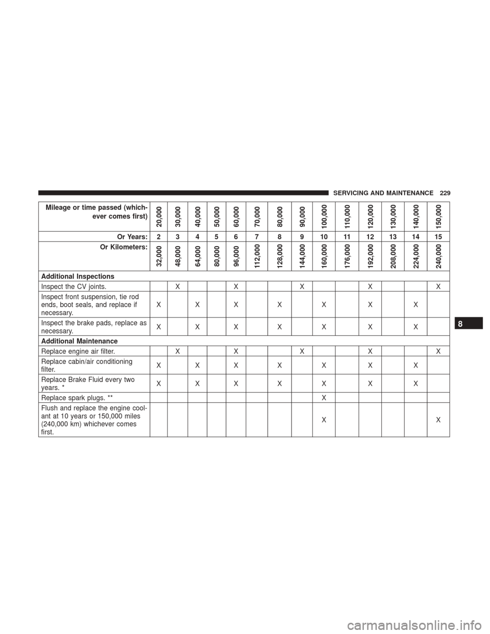
Inspect the CV joints. XX X XX
Inspect front suspension, tie rod
ends, boot seals, and replace if
necessary. XXX X X X X
Inspect the brake pads, replace as
necessary. XXX X X X X
Additional Maintenance
Replace engine air filter. XX X XX
Replace cabin/air conditioning
filter. XXX X X X X
Replace Brake Fluid every two
years. * XXX X X X X
Replace spark plugs. ** X
Flush and replace the engine cool-
ant at 10 years or 150,000 miles
(240,000 km) whichever comes
first. XX
8
SERVICING AND MAINTENANCE 229
Page 265 of 337

Keep dismounted tires in a cool, dry place with as little
exposure to light as possible. Protect tires from contact with
oil, grease, and gasoline.
Replacement Tires
The tires on your new vehicle provide a balance of many
characteristics. They should be inspected regularly for
wear and correct cold tire inflation pressures. The manu-
facturer strongly recommends that you use tires equivalent
to the originals in size, quality and performance when
replacement is needed. Refer to the paragraph on “Tread
Wear Indicators” in this section. Refer to the Tire and
Loading Information placard or the Vehicle Certification
Label for the size designation of your tire. The Load Index
and Speed Symbol for your tire will be found on the
original equipment tire sidewall.
See the Tire Sizing Chart example found in the “Tire Safety
Information” section of this manual for more information
relating to the Load Index and Speed Symbol of a tire.
It is recommended to replace the two front tires or two rear
tires as a pair. Replacing just one tire can seriously affect
your vehicle’s handling. If you ever replace a wheel, make
sure that the wheel’s specifications match those of the
original wheels.It is recommended you contact your authorized tire dealer
or original equipment dealer with any questions you may
have on tire specifications or capability. Failure to use
equivalent replacement tires may adversely affect the
safety, handling, and ride of your vehicle.
WARNING!
•
Do not use a tire, wheel size, load rating, or speed
rating other than that specified for your vehicle.
Some combinations of unapproved tires and wheels
may change suspension dimensions and perfor-
mance characteristics, resulting in changes to steer-
ing, handling, and braking of your vehicle. This can
cause unpredictable handling and stress to steering
and suspension components. You could lose control
and have a collision resulting in serious injury or
death. Use only the tire and wheel sizes with load
ratings approved for your vehicle.
• Never use a tire with a smaller load index or capacity,
other than what was originally equipped on your
vehicle. Using a tire with a smaller load index could
result in tire overloading and failure. You could lose
control and have a collision.
(Continued)
8
SERVICING AND MAINTENANCE 263
Page 271 of 337

Dark Vapor Chrome, Black Satin Chrome, or Low Gloss
Clear Coat Wheels
CAUTION!
If your vehicle is equipped with these specialty
wheels, DO NOT USE wheel cleaners, abrasives, or
polishing compounds. They will permanently damage
this finish and such damage is not covered by the New
Vehicle Limited Warranty. HAND WASH ONLY US-
ING MILD SOAP AND WATER WITH A SOFT
CLOTH. Used on a regular basis; this is all that is
required to maintain this finish.
Tire Chains (Traction Devices)
Use of traction devices require sufficient tire-to-body clear-
ance. Follow these recommendations to guard against
damage.
•Traction device must be of proper size for the tire, as
recommended by the traction device manufacturer.
• Install on front tires only.
• Tire chains for a 225/75R16 tire with a Quality Chain
Corp Light Truck Highway Service (Non-Cam) tire chain
or equivalent is recommended.
WARNING!
Using tires of different size and type (M+S, Snow)
between front and rear axles can cause unpredictable
handling. You could lose control and have a collision.
CAUTION!
To avoid damage to your vehicle or tires, observe the
following precautions:
• Because of restricted traction device clearance be-
tween tires and other suspension components, it is
important that only traction devices in good condi-
tion are used. Broken devices can cause serious
damage. Stop the vehicle immediately if noise occurs
that could indicate device breakage. Remove the
damaged parts of the device before further use.
• Install device as tightly as possible and then re-
tighten after driving about ½ mile (0.8 km).
• Do not exceed 30 mph (48 km/h).
• Drive cautiously and avoid severe turns and large
bumps, especially with a loaded vehicle.
• Do not drive for a prolonged period on dry pave-
ment.
(Continued)
8
SERVICING AND MAINTENANCE 269