light Ram ProMaster 2018 Service Manual
[x] Cancel search | Manufacturer: RAM, Model Year: 2018, Model line: ProMaster, Model: Ram ProMaster 2018Pages: 204, PDF Size: 4 MB
Page 94 of 204
WARNING!
cause the “Malfunction Indicator Light”
to turn on.
• A fire may result if fuel is pumped into a
portable container that is inside of a
vehicle. You could be burned. Always
place fuel containers on the ground
while filling.
CAUTION!
• Damage to the fuel system or emissionscontrol system could result from using
an improper fuel tank filler tube cap.
• A poorly fitting fuel filler cap could let
impurities into the fuel system.
• A poorly fitting fuel filler cap may cause
the “Malfunction Indicator Light (MIL)”
to turn on.
• To avoid fuel spillage and overfilling, do
not “top off” the fuel tank after filling.
When the fuel nozzle “clicks” or shuts
off, the fuel tank is full. NOTE:
• When the fuel nozzle “clicks” or shuts off,
the fuel tank is full.
• Tighten the fuel filler cap until you hear a “clicking” sound. This is an indication that
the fuel filler cap is properly tightened.
• If the gas cap is not tightened properly, the MIL may come on. Be sure the gas cap is
tightened every time the vehicle is
refueled.Materials Added To Fuel
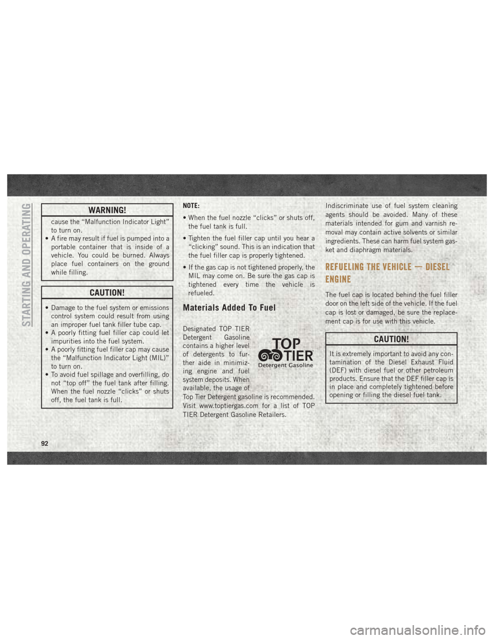
Designated TOP TIER
Detergent Gasoline
contains a higher level
of detergents to fur-
ther aide in minimiz-
ing engine and fuel
system deposits. When
available, the usage of
Top Tier Detergent gasoline is recommended.
Visit www.toptiergas.com for a list of TOP
TIER Detergent Gasoline Retailers. Indiscriminate use of fuel system cleaning
agents should be avoided. Many of these
materials intended for gum and varnish re-
moval may contain active solvents or similar
ingredients. These can harm fuel system gas-
ket and diaphragm materials.
REFUELING THE VEHICLE — DIESEL
ENGINE
The fuel cap is located behind the fuel filler
door on the left side of the vehicle. If the fuel
cap is lost or damaged, be sure the replace-
ment cap is for use with this vehicle.
CAUTION!
It is extremely important to avoid any con-
tamination of the Diesel Exhaust Fluid
(DEF) with diesel fuel or other petroleum
products. Ensure that the DEF filler cap is
in place and completely tightened before
opening or filling the diesel fuel tank.
STARTING AND OPERATING
92
Page 108 of 204
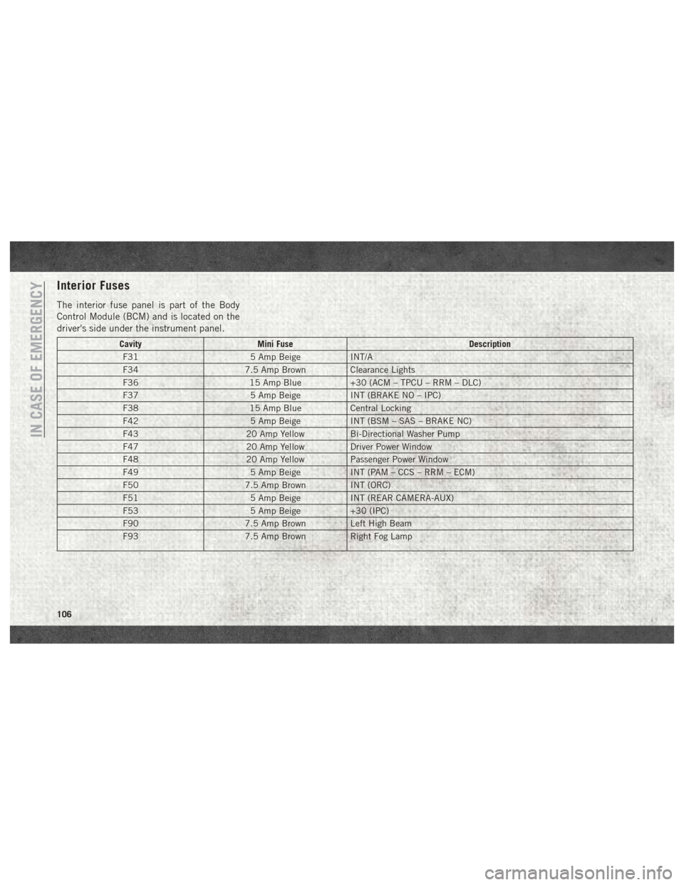
Interior Fuses
The interior fuse panel is part of the Body
Control Module (BCM) and is located on the
driver's side under the instrument panel.
CavityMini Fuse Description
F31 5 Amp BeigeINT/A
F34 7.5 Amp Brown Clearance Lights
F36 15 Amp Blue+30 (ACM – TPCU – RRM – DLC)
F37 5 Amp BeigeINT (BRAKE NO – IPC)
F38 15 Amp BlueCentral Locking
F42 5 Amp BeigeINT (BSM – SAS – BRAKE NC)
F43 20 Amp YellowBi-Directional Washer Pump
F47 20 Amp YellowDriver Power Window
F48 20 Amp YellowPassenger Power Window
F49 5 Amp BeigeINT (PAM – CCS – RRM – ECM)
F50 7.5 Amp Brown INT (ORC)
F51 5 Amp BeigeINT (REAR CAMERA-AUX)
F53 5 Amp Beige+30 (IPC)
F90 7.5 Amp Brown Left High Beam
F93 7.5 Amp Brown Right Fog Lamp
IN CASE OF EMERGENCY
106
Page 116 of 204

WARNING!
Being under a jacked-up vehicle is danger-
ous. The vehicle could slip off the jack and
fall on you. You could be crushed. Never
get any part of your body under a vehicle
that is on a jack. If you need to get under a
raised vehicle, take it to a service center
where it can be raised on a lift.3. Place the wrench handle and lug bolt
adapter on the jack screw and turn to the
right until the jack head is properly en-
gaged in the described location. Do not
raise the vehicle until you are sure the jack
is securely engaged.
4. Raise the vehicle by turning the jack screw to the right, using the wrench
handle and lug bolt adapter. Raise the
vehicle only until the tire just clears the
surface and enough clearance is obtained
to install the spare tire. Minimum tire lift
provides maximum stability.
WARNING!
Raising the vehicle higher than necessary
can make the vehicle less stable. It could
slip off the jack and hurt someone near it.
Raise the vehicle only enough to remove
the tire.
5. Remove the wheel lug bolts. For vehicles with wheel covers, remove the cover from
the wheel by hand. Do not pry the wheel
cover off. Then pull the wheel off the hub. 6. Install the spare tire. Lightly tighten the
wheel lug bolts.
WARNING!
To avoid the risk of forcing the vehicle off
the jack, do not tighten the wheel nuts
fully until the vehicle has been lowered.
Failure to follow this warning may result in
serious injury.
Front Jacking Location
Mounting Spare Tire
IN CASE OF EMERGENCY
114
Page 126 of 204
SCHEDULED SERVICING — GASOLINE
ENGINE
Your vehicle is equipped with an automatic
oil change indicator system. The oil change
indicator system will remind you that it is
time to take your vehicle in for scheduled
maintenance.
Based on engine operation conditions, the oil
change indicator message will illuminate in
the instrument cluster. This means that ser-
vice is required for your vehicle. Operating
conditions such as frequent short-trips,
trailer tow, and extremely hot or cold ambient
temperatures will influence when the “Oil
Change Required” message is displayed. Se-
vere Operating Conditions can cause the
change oil message to illuminate as early as
3,500 miles (5,600 km) since last reset.
Have your vehicle serviced as soon as pos-
sible, within the next 500 miles (805 km).
Your authorized dealer will reset the oil change
indicator message after completing the sched-
uled oil change. If a scheduled oil change is
performed by someone other than your autho-
rized dealer, the message can be reset byreferring to the steps described under “Instru-
ment Cluster Display” in “Getting To Know
Your Instrument Panel” in your Owner’s
Manual on
www.ramtrucks.com/en/owners/
manuals for further information.
NOTE:
Under no circumstances should oil change
intervals exceed 10,000 miles (16,000 km),
twelve months or 350 hours of engine run
time, whichever comes first. The 350 hours
of engine run or idle time is generally only a
concern for fleet customers.
Severe Duty All Models
Change Engine Oil at 4,000 miles
(6,500 km) or 350 hours of engine run time
if the vehicle is operated in a dusty and off
road environment or is operated predomi-
nately at idle or only very low engine RPM’s.
This type of vehicle use is considered Severe
Duty. Once A Month Or Before A Long Trip:
• Check engine oil level
• Check windshield washer fluid level
• Check the tire inflation pressures and look
for unusual wear or damage
• Check the fluid levels of the coolant reser- voir, brake master cylinder, and power
steering and fill as needed
• Check function of all interior and exterior lights
SERVICING AND MAINTENANCE
124
Page 130 of 204
Heavy Duty Use Of The Vehicle
Change engine oil at 4,000 miles (6,500 km)
or 350 hours of engine run time if the vehicle
is operated in a dusty and off road environ-
ment or is operated predominately at idle or
only very low engine RPM’s. This type of
vehicle use is considered Severe Duty.
SCHEDULED MAINTENANCE — DIESEL
ENGINE
Your vehicle is equipped with an automatic
oil change indicator system. The oil change
indicator system will remind you that it is
time to take your vehicle in for scheduled
maintenance.
Based on engine operation conditions, the oil
change indicator message will illuminate in
the instrument cluster. This means that ser-
vice is required for your vehicle. Operating
conditions such as frequent short-trips,
trailer tow, and extremely hot or cold ambient
temperatures will influence when the “Oil
Change Required” message is displayed. Se-
vere Operating Conditions can cause the
change oil message to illuminate as early as3,500 miles (5,600 km) since last reset.
Have your vehicle serviced as soon as pos-
sible, within the next 500 miles (805 km).
NOTE:
Under no circumstances should oil change
intervals exceed 18,500 miles (29,773 km)
or twelve months, whichever comes first.
Once A Month Or Before A Long Trip:
• Check engine oil level
• Check windshield washer fluid level
• Check the tire inflation pressures and look
for unusual wear or damage
• Check the fluid levels of the coolant reser- voir, brake master cylinder, and power
steering, and fill as needed
• Check function of all interior and exterior lights
Maintenance Plan — Diesel Fuel
Up To B5 Biodiesel
Required Maintenance Intervals.
Refer to the maintenance schedules on the
following page for the required maintenance
intervals.
At Every Oil Change Interval As Indicated By The Oil Change Indicator System:
• Change oil and filter.
• Rotate the tires. Rotate at the first sign of
irregular wear, even if it occurs before your
next scheduled service.
• Inspect battery and clean and tighten ter- minals as required.
• Inspect brake pads, rotors, hoses and park brake.
• Inspect engine cooling system protection and hoses.
• Inspect exhaust system.
• Inspect engine air cleaner if using in dusty or off-road conditions.
SERVICING AND MAINTENANCE
128
Page 136 of 204

RAISING THE VEHICLE
In the case where it is necessary to raise the
vehicle, go to an authorized dealer or service
station.
TIRES
Tire Safety Information
Tire safety information will cover aspects of
the following information: Tire Markings, Tire
Identification Numbers, Tire Terminology and
Definitions, Tire Pressures, and Tire Loading.
Tire MarkingsNOTE:
• P (Passenger) — Metric tire sizing is basedon U.S. design standards. P-Metric tires
have the letter “P” molded into the sidewall
preceding the size designation. Example:
P215/65R15 95H.
• European — Metric tire sizing is based on European design standards. Tires designed
to this standard have the tire size molded
into the sidewall beginning with the section
width. The letter "P" is absent from this tire
size designation. Example: 215/
65R15 96H.
• LT (Light Truck) — Metric tire sizing is based on U.S. design standards. The size
designation for LT-Metric tires is the same
as for P-Metric tires except for the letters
“LT” that are molded into the sidewall
preceding the size designation. Example:
LT235/85R16.
• Temporary spare tires are designed for tem- porary emergency use only. Temporary high
pressure compact spare tires have the letter
“T” or “S” molded into the sidewall preced-
ing the size designation. Example: T145/
80D18 103M.
Tire Markings
1 — U.S. DOT
Safety Stan-
dards Code
(TIN) 4 — Maximum
Load
2 — Size Desig-
nation 5 — Maximum
Pressure
3 — Service
Description 6 — Treadwear,
Traction and
Temperature
Grades
SERVICING AND MAINTENANCE
134
Page 137 of 204

• High flotation tire sizing is based on U.S.design standards and it begins with the tire
diameter molded into the sidewall. Ex-
ample: 31x10.5 R15 LT.
Tire Sizing Chart
EXAMPLE:
Example Size Designation: P215/65R15XL 95H, 215/65R15 96H, LT235/85R16C, T145/80D18 103M, 31x10.5 R15 LT
P = Passenger car tire size based on U.S. design standards, or
"....blank...." = Passenger car tire based on European design standards, or
LT = Light truck tire based on U.S. design standards, or
TorS= Temporary spare tire or
31 = Overall diameter in inches (in)
215, 235, 145 = Section width in millimeters (mm)
65, 85, 80 = Aspect ratio in percent (%)
• Ratio of section height to section width of tire, or
10.5 = Section width in inches (in)
R = Construction code
• "R" means radial construction, or
• "D" means diagonal or bias construction
15, 16, 18 = Rim diameter in inches (in)
135
Page 138 of 204
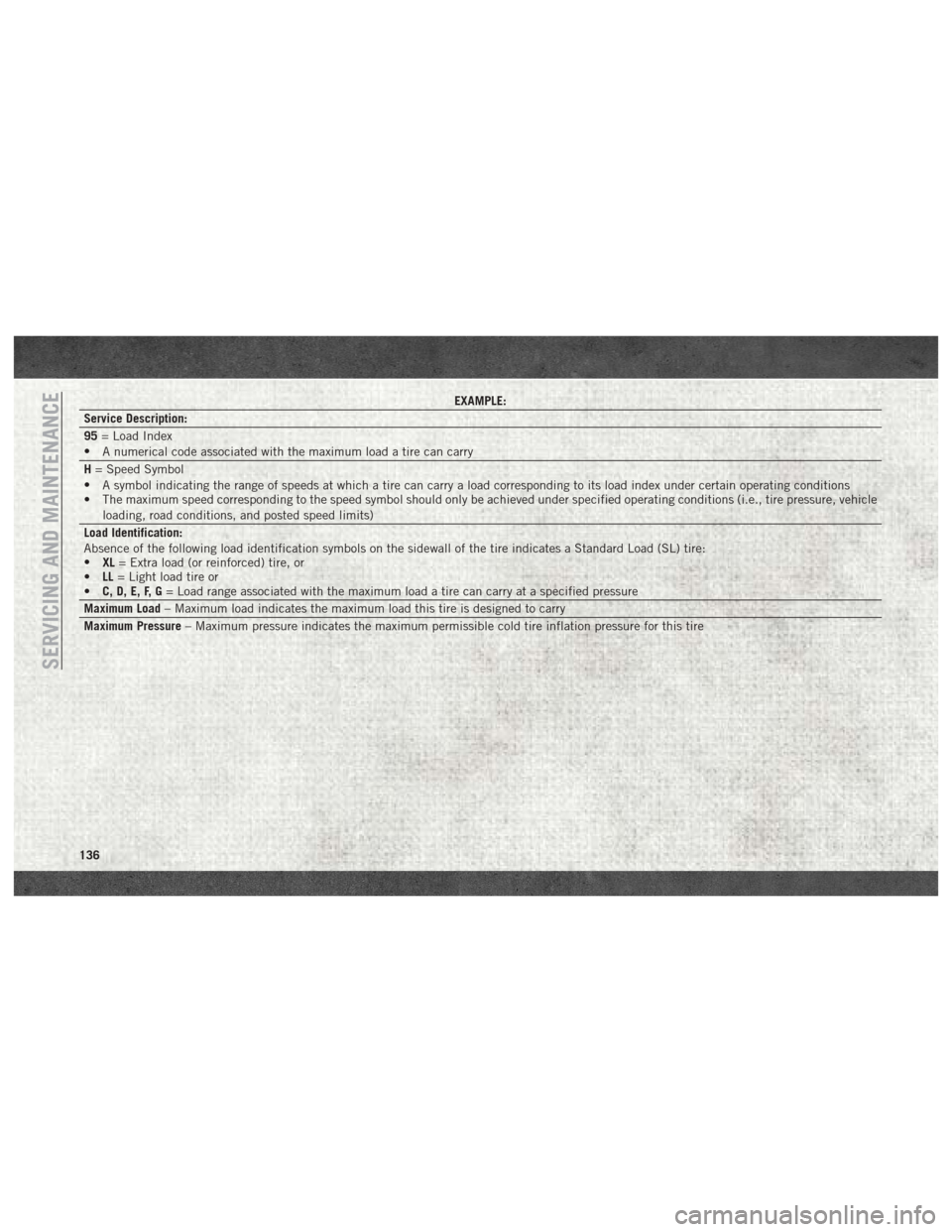
EXAMPLE:
Service Description:
95 = Load Index
• A numerical code associated with the maximum load a tire can carry
H = Speed Symbol
• A symbol indicating the range of speeds at which a tire can carry a load corresponding to its load index under certain operating conditions
• The maximum speed corresponding to the speed symbol should only be achieved under specified operating conditions (i.e., tire pressure, vehicle
loading, road conditions, and posted speed limits)
Load Identification:
Absence of the following load identification symbols on the sidewall of the tire indicates a Standard Load (SL) tire:
• XL= Extra load (or reinforced) tire, or
• LL= Light load tire or
• C, D, E, F, G = Load range associated with the maximum load a tire can carry at a specified pressure
Maximum Load – Maximum load indicates the maximum load this tire is designed to carry
Maximum Pressure – Maximum pressure indicates the maximum permissible cold tire inflation pressure for this tire
SERVICING AND MAINTENANCE
136
Page 147 of 204

Tread Wear Indicators
Tread wear indicators are in the original
equipment tires to help you in determining
when your tires should be replaced.
These indicators are molded into the bottom
of the tread grooves. They will appear as
bands when the tread depth becomes a
1/16 of an inch (1.6 mm). When the tread is
worn to the tread wear indicators, the tire
should be replaced. Refer to “Replacement
Tires” in this section for further information.
Life Of Tire
The service life of a tire is dependent upon
varying factors including, but not limited to:
• Driving style.
• Tire pressure - Improper cold tire inflationpressures can cause uneven wear patterns
to develop across the tire tread. These ab-
normal wear patterns will reduce tread life,
resulting in the need for earlier tire replace-
ment.
• Distance driven.
• Performance tires, tires with a speed rating of V or higher, and Summer tires typically
have a reduced tread life. Rotation of these
tires per the vehicle scheduled mainte-
nance is highly recommended.
WARNING!
Tires and the spare tire should be replaced
after six years, regardless of the remaining
tread. Failure to follow this warning can
result in sudden tire failure. You could lose
control and have a collision resulting in
serious injury or death. Keep dismounted tires in a cool, dry place
with as little exposure to light as possible.
Protect tires from contact with oil, grease,
and gasoline.
Replacement Tires
The tires on your new vehicle provide a bal-
ance of many characteristics. They should be
inspected regularly for wear and correct cold
tire inflation pressures. The manufacturer
strongly recommends that you use tires
equivalent to the originals in size, quality and
performance when replacement is needed.
Refer to the paragraph on “Tread Wear Indi-
cators” in this section. Refer to the Tire and
Loading Information placard or the Vehicle
Certification Label for the size designation of
your tire. The Load Index and Speed Symbol
for your tire will be found on the original
equipment tire sidewall.
See the Tire Sizing Chart example found in
the “Tire Safety Information” section of this
manual for more information relating to the
Load Index and Speed Symbol of a tire.
Tire Tread
1 — Worn Tire
2 — New Tire
145
Page 162 of 204
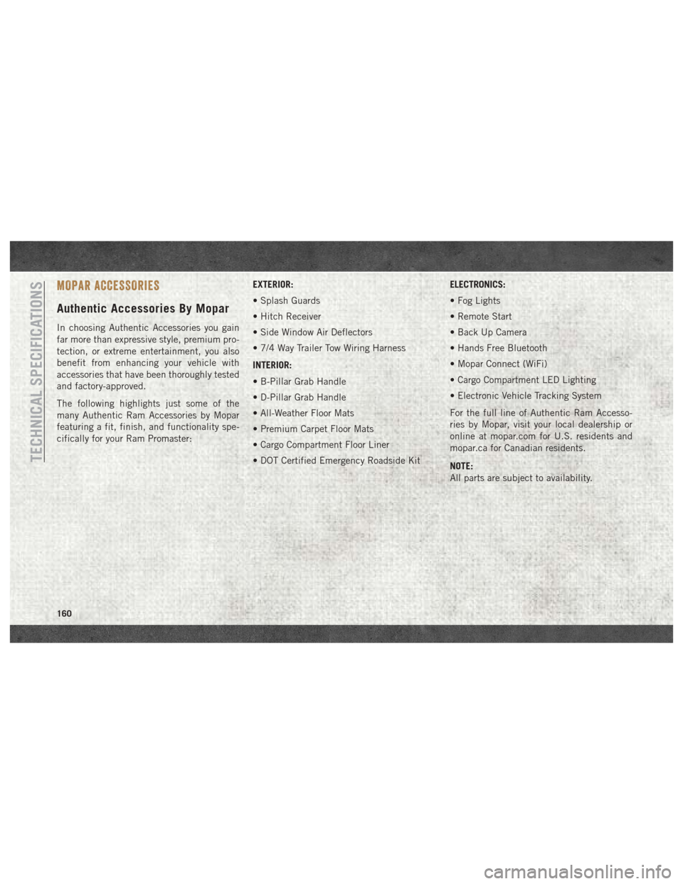
MOPAR ACCESSORIES
Authentic Accessories By Mopar
In choosing Authentic Accessories you gain
far more than expressive style, premium pro-
tection, or extreme entertainment, you also
benefit from enhancing your vehicle with
accessories that have been thoroughly tested
and factory-approved.
The following highlights just some of the
many Authentic Ram Accessories by Mopar
featuring a fit, finish, and functionality spe-
cifically for your Ram Promaster:EXTERIOR:
• Splash Guards
• Hitch Receiver
• Side Window Air Deflectors
• 7/4 Way Trailer Tow Wiring Harness
INTERIOR:
• B-Pillar Grab Handle
• D-Pillar Grab Handle
• All-Weather Floor Mats
• Premium Carpet Floor Mats
• Cargo Compartment Floor Liner
• DOT Certified Emergency Roadside Kit ELECTRONICS:
• Fog Lights
• Remote Start
• Back Up Camera
• Hands Free Bluetooth
• Mopar Connect (WiFi)
• Cargo Compartment LED Lighting
• Electronic Vehicle Tracking System
For the full line of Authentic Ram Accesso-
ries by Mopar, visit your local dealership or
online at mopar.com for U.S. residents and
mopar.ca for Canadian residents.
NOTE:
All parts are subject to availability.
TECHNICAL SPECIFICATIONS
160