fuel Ram ProMaster 2018 User Guide
[x] Cancel search | Manufacturer: RAM, Model Year: 2018, Model line: ProMaster, Model: Ram ProMaster 2018Pages: 204, PDF Size: 4 MB
Page 24 of 204
IconDescription
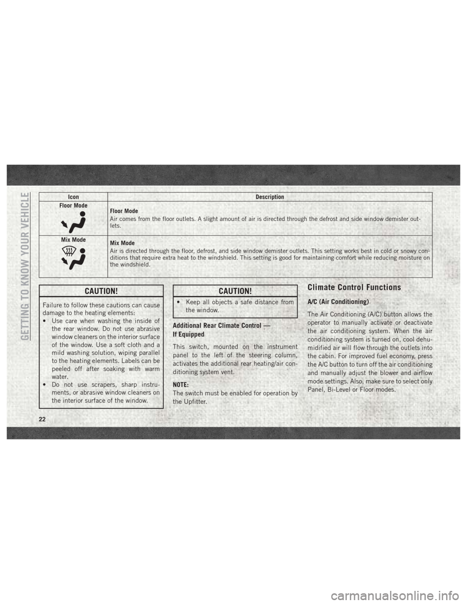
Floor Mode
Floor Mode
Air comes from the floor outlets. A slight amount of air is directed through the defrost and side window demister out-
lets.
Mix Mode
Mix Mode
Air is directed through the floor, defrost, and side window demister outlets. This setting works best in cold or snowy con-
ditions that require extra heat to the windshield. This setting is good for maintaining comfort while reducing moisture on
the windshield.
CAUTION!
Failure to follow these cautions can cause
damage to the heating elements:
• Use care when washing the inside of the rear window. Do not use abrasive
window cleaners on the interior surface
of the window. Use a soft cloth and a
mild washing solution, wiping parallel
to the heating elements. Labels can be
peeled off after soaking with warm
water.
• Do not use scrapers, sharp instru-
ments, or abrasive window cleaners on
the interior surface of the window.
CAUTION!
• Keep all objects a safe distance fromthe window.
Additional Rear Climate Control —
If Equipped
This switch, mounted on the instrument
panel to the left of the steering column,
activates the additional rear heating/air con-
ditioning system vent.
NOTE:
The switch must be enabled for operation by
the Upfitter.
Climate Control Functions
A/C (Air Conditioning)
The Air Conditioning (A/C) button allows the
operator to manually activate or deactivate
the air conditioning system. When the air
conditioning system is turned on, cool dehu-
midified air will flow through the outlets into
the cabin. For improved fuel economy, press
the A/C button to turn off the air conditioning
and manually adjust the blower and airflow
mode settings. Also, make sure to select only
Panel, Bi-Level or Floor modes.
GETTING TO KNOW YOUR VEHICLE
22
Page 34 of 204
• When count down is over (0 mile left),continuous message "Speed limited at re-
fuel or next engine start" is shown in the
Display. In this case, if an engine restart or
a diesel refuel action in engine-on condi-
tion is performed, vehicle’s speed will be
limited to 5 mph and continuous message
"Speed limited DEF low" is shown in the
Display.
• The restriction becomes inactive as soon as the DEF refill event is detected (minimum
quantity to be added is 1 gallon). Transmission Messages
Refer to “Instrument Cluster Messages” un-
der “Automated Manual Transmission” in
“Starting And Operating” for detailed infor-
mation on transmission warning messages.
•Gear unavailable
• Shift not allowed
• Manual unavailable
• Automatic unavailable
• Reduce gear changes
• Press brake and try again
• Transmission temperature high
• Press brake pedal
• Press brake pedal startup delayed
• Shift to neutral
• Tow/Haul ON
• Service transmission
GETTING TO KNOW YOUR INSTRUMENT PANEL
32
Page 39 of 204
Yellow Warning Lights
— Vehicle Security Warning Light
This telltale will illuminate when the vehicle
security alarm system has detected an at-
tempt was made to break into the vehicle.
— Tire Pressure Monitoring System
(TPMS) Warning Light
The warning light switches on and a message
is displayed to indicate that the tire pressure
is lower than the recommended value and/or
that slow pressure loss is occurring. In these
cases, optimal tire duration and fuel con-
sumption may not be guaranteed.
Should one or more tires be in the condition
mentioned above, the display will show the
indications corresponding to each tire in
sequence.
CAUTION!
Do not continue driving with one or more
flat tires as handling may be compro-
mised. Stop the vehicle, avoiding sharp
braking and steering. If a tire puncture
CAUTION!
occurs, repair immediately using the dedi-
cated tire repair kit and contact your au-
thorized dealer as soon as possible.
Each tire, including the spare (if provided),
should be checked monthly when cold and
inflated to the inflation pressure recom-
mended by the vehicle manufacturer on the
vehicle placard or tire inflation pressure la-
bel. (If your vehicle has tires of a different
size than the size indicated on the vehicle
placard or tire inflation pressure label, you
should determine the proper tire inflation
pressure for those tires.)
As an added safety feature, your vehicle has
been equipped with a tire pressure monitor-
ing system (TPMS) that illuminates a low tire
pressure telltale when one or more of your
tires is significantly under-inflated. Accord-
ingly, when the low tire pressure telltale illu-
minates, you should stop and check your tires
as soon as possible, and inflate them to the
proper pressure. Driving on a significantly
under-inflated tire causes the tire to overheat and can lead to tire failure. Under-inflation
also reduces fuel efficiency and tire tread
life, and may affect the vehicle’s handling
and stopping ability.
Please note that the TPMS is not a substitute
for proper tire maintenance, and it is the
driver’s responsibility to maintain correct tire
pressure, even if under-inflation has not
reached the level to trigger illumination of the
TPMS low tire pressure telltale.
Your vehicle has also been equipped with a
TPMS malfunction indicator to indicate when
the system is not operating properly. The
TPMS malfunction indicator is combined
with the low tire pressure telltale. When the
system detects a malfunction, the telltale will
flash for approximately one minute and then
remain continuously illuminated. This se-
quence will continue upon subsequent ve-
hicle start-ups as long as the malfunction
exists. When the malfunction indicator is
illuminated, the system may not be able to
detect or signal low tire pressure as intended.
TPMS malfunctions may occur for a variety of
reasons, including the installation of replace-
ment or alternate tires or wheels on the ve-
37
Page 41 of 204
Certain conditions, such as a loose or missing
gas cap, poor quality fuel, etc., may illumi-
nate the light after engine start. The vehicle
should be serviced if the light stays on
through several typical driving styles. In most
situations, the vehicle will drive normally and
will not require towing.
When the engine is running, the MIL may
flash to alert serious conditions that could
lead to immediate loss of power or severe
catalytic converter damage. The vehicle
should be serviced as soon as possible if this
occurs.
WARNING!
A malfunctioning catalytic converter, as
referenced above, can reach higher tem-
peratures than in normal operating condi-
tions. This can cause a fire if you drive
slowly or park over flammable substances
such as dry plants, wood, cardboard, etc.
This could result in death or serious injury
to the driver, occupants or others.
CAUTION!
Prolonged driving with the Malfunction
Indicator Light (MIL) on could cause dam-
age to the vehicle control system. It also
could affect fuel economy and driveability.
If the MIL is flashing, severe catalytic
converter damage and power loss will soon
occur. Immediate service is required.
— Anti-Lock Brake (ABS) Warning
Light
This light monitors the Anti-Lock Brake Sys-
tem (ABS). The light will turn on when the
ignition is placed in the ON/RUN or MAR/ON/
RUN position and may stay on for as long as
four seconds.
If the ABS light remains on or turns on while
driving, then the Anti-Lock portion of the
brake system is not functioning and service is
required. However, the conventional brake
system will continue to operate normally if
the brake warning light is not on. If the ABS light is on, the brake system
should be serviced as soon as possible to
restore the benefits of Anti-Lock Brakes. If
the ABS light does not turn on when the
ignition is placed in the ON/RUN or MAR/ON/
RUN position, have the light inspected by an
authorized dealer.
— Generic Warning Light
The Generic Warning Light will illuminate if
any of the following conditions occur: Engine
Oil Pressure Sensor Failure, External Light
Failure, Fuel Cut-Off intervention or fail,
Parking Sensor Failure, DST System Failure.
The telltale will remain on fixed in case of
swivel seat failure and on blinking in case of
Air Bag Warning Light Failure. Contact an
authorized dealer immediately for service.
39
Page 44 of 204
ONBOARD DIAGNOSTIC SYSTEM —
OBD II
Your vehicle is equipped with a sophisticated
Onboard Diagnostic system called OBD II.
This system monitors the performance of the
emissions, engine, and transmission control
systems. When these systems are operating
properly, your vehicle will provide excellent
performance and fuel economy, as well as
engine emissions well within current govern-
ment regulations.
If any of these systems require service, the
OBD II system will turn on the Malfunction
Indicator Light (MIL). It will also store diag-
nostic codes and other information to assist
your service technician in making repairs.
Although your vehicle will usually be drivable
and not need towing, see your authorized
dealer for service as soon as possible.
CAUTION!
• Prolonged driving with the MIL on couldcause further damage to the emission
control system. It could also affect fuel
economy and driveability. The vehicle
must be serviced before any emissions
tests can be performed.
• If the MIL is flashing while the vehicle is
running, severe catalytic converter dam-
age and power loss will soon occur. Im-
mediate service is required.
Onboard Diagnostic System (OBD
II) Cybersecurity
Your vehicle is required to have an Onboard
Diagnostic system (OBD II) and a connection
port to allow access to information related to
the performance of your emissions controls.
Authorized service technicians may need to
access this information to assist with the
diagnosis and service of your vehicle and
emissions system.
WARNING!
• ONLY an authorized service technicianshould connect equipment to the OBD II
connection port in order to diagnose or
service your vehicle.
• If unauthorized equipment is connected
to the OBD II connection port, such as a
driver-behavior tracking device, it may:• Be possible that vehicle systems,
including safety related systems,
could be impaired or a loss of ve-
hicle control could occur that may
result in an accident involving seri-
ous injury or death.
• Access, or allow others to access,
information stored in your vehicle
systems, including personal infor-
mation.
For further information, refer to “Cybersecurity”
in “Multimedia”.
GETTING TO KNOW YOUR INSTRUMENT PANEL
42
Page 47 of 204
CAUTION!
• The TPMS has been optimized for theoriginal equipment tires and wheels.
TPMS pressures and warning have been
established for the tire size equipped on
your vehicle. Undesirable system opera-
tion or sensor damage may result when
using replacement equipment that is not
of the same size, type, and/or style.
Aftermarket wheels can cause sensor
damage.
• Using aftermarket tire sealants may
cause the Tire Pressure Monitoring Sys-
tem (TPMS) sensor to become inoper-
able. After using an aftermarket tire
sealant it is recommended that you take
your vehicle to an authorized dealership
to have your sensor function checked.
• After inspecting or adjusting the tire
pressure always reinstall the valve stem
cap. This will prevent moisture and dirt
from entering the valve stem, which
could damage the TPMS sensor. NOTE:
• The TPMS is not intended to replace nor-
mal tire care and maintenance or to provide
warning of a tire failure or condition.
• The TPMS should not be used as a tire pressure gauge while adjusting your tire
pressure.
• Driving on a significantly under-inflated tire causes the tire to overheat and can lead to
tire failure. Under-inflation also reduces
fuel efficiency and tire tread life, and may
affect the vehicle’s handling and stopping
ability.
• The TPMS is not a substitute for proper tire maintenance, and it is the driver’s respon-
sibility to maintain correct tire pressure
using an accurate tire pressure gauge, even
if under-inflation has not reached the level
to trigger illumination of the TPM Telltale
Light.
• Seasonal temperature changes will affect tire pressure, and the TPMS will monitor
the actual tire pressure in the tire.
Base System
This is the TPMS warning indicator
located in the instrument cluster.
The TPMS uses wireless technology
with wheel rim mounted electronic sensors to
monitor tire pressure levels. Sensors,
mounted to each wheel as part of the valve
stem, transmit tire pressure readings to the
Receiver Module.
NOTE:
It is particularly important for you to check
the tire pressure in all of the tires on your
vehicle regularly and to maintain the proper
pressure.
The TPMS consists of the following compo-
nents:
• Receiver Module.
• Four Tire Pressure Monitoring Sensors.
• Tire Pressure Monitoring Telltale Light.
45
Page 64 of 204
Fuel Cut Off Switch
Your vehicle is equipped with a Fuel Cut Off
safety switch. In the event of an accident, if
the communication network remains intact,
and the power remains intact, depending on
the nature of the event, the Fuel Cut Off
Switch may perform the following functions:
• Cut off fuel to the engine and turn off theengine.
• Flash hazard lights as long as the battery has power or until the hazard light button is
pressed. The hazard lights can be deacti-
vated by pressing the hazard light button.
• Turn on the interior lights, which remain on as long as the battery has power.
• Unlock the power door locks. NOTE:
After an accident, remember to cycle the
ignition to the STOP (OFF/LOCK) position
and remove the key from the ignition switch
to avoid draining the battery. Carefully check
the vehicle for fuel leaks in the engine com-
partment and on the ground near the engine
compartment and fuel tank before resetting
the system and starting the engine. If there
are no fuel leaks or damage to the vehicle
electrical devices (e.g. headlights) after an
accident, reset the Fuel Cut Off Switch by
following the procedure described below.
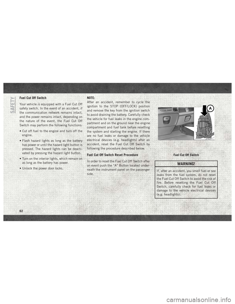
Fuel Cut Off Switch Reset Procedure
In order to reset the Fuel Cut Off Switch after
an event push the “A” Button located under-
neath the instrument panel on the passenger
side.WARNING!
If, after an accident, you smell fuel or see
leaks from the fuel system, do not reset
the Fuel Cut Off Switch to avoid the risk of
fire. Before resetting the Fuel Cut Off
Switch, carefully check for fuel leaks or
damage to the vehicle electrical devices
(e.g. headlights).
Fuel Cut Off Switch
SAFETY
62
Page 74 of 204
Periodic Safety Checks You
Should Make Outside The Vehicle
Tires
Examine tires for excessive tread wear and
uneven wear patterns. Check for stones,
nails, glass, or other objects lodged in the
tread or sidewall. Inspect the tread for cuts
and cracks. Inspect sidewalls for cuts,
cracks, and bulges. Check the wheel bolts for
tightness. Check the tires (including spare)
for proper cold inflation pressure.
Lights
Have someone observe the operation of brake
lights and exterior lights while you work the
controls. Check turn signal and high beam
indicator lights on the instrument panel.
Door Latches
Check for proper closing, latching, and lock-
ing.
Fluid Leaks
Check area under the vehicle after overnight
parking for fuel, coolant, oil, or other fluid
leaks. Also, if gasoline fumes are detected or
if fuel, or brake fluid leaks are suspected. The
cause should be located and corrected imme-
diately.
SAFETY
72
Page 75 of 204

STARTING AND OPERATING
STARTING THE ENGINE —
GAS ENGINE..................74
Normal Starting ................74
STARTING THE ENGINE —
DIESEL ENGINE................74
Normal Starting Procedure .........75
Extreme Cold Weather ............76
NORMAL OPERATION.............76
Stopping The Diesel Engine ........76
ENGINE BREAK-IN RECOMMENDATIONS —
GASOLINE ENGINE..............77
ENGINE BREAK-IN RECOMMENDATIONS –
DIESEL ENGINE ................77
ELECTRIC PARK BRAKE (EPB) —
DIESEL ONLY (IF EQUIPPED) ........78
Loss Of Electric Power............80
AUTOMATED MANUAL TRANSMISSION —
DIESEL ONLY..................81
Gear Ranges ..................82
Parking The Vehicle ..............84 Instrument Cluster Messages
........86
Towing The Vehicle ..............88
SPEED CONTROL...............89
To Activate...................89
To Set A Desired Speed ...........89
To Vary The Speed Setting ..........89
To Accelerate For Passing ..........90
To Resume Speed ...............91
To Deactivate ..................91
PARKSENSE REAR PARK ASSIST .....91
PARKVIEW REAR BACK-UP CAMERA . . .91
REFUELING THE VEHICLE —
GAS ENGINE ..................91
Materials Added To Fuel ..........92
REFUELING THE VEHICLE —
DIESEL ENGINE................92
Diesel Exhaust Fluid .............93
Adding Diesel Exhaust Fluid ........94
TRAILER TOWING..............95
Trailer Towing Weights (Maximum Trailer
Weight Ratings)................95
RECREATIONAL TOWING (BEHIND
MOTORHOME, ETC.) .............96
Towing This Vehicle Behind
Another Vehicle................96
Recreational Towing — Gasoline Engine
All Models ...................97
STARTING AND OPERATING
73
Page 77 of 204
CAUTION!
If the “Generic Warning Light” remains on
and a “Service Fuel Filter” message dis-
plays, DO NOT START engine before you
drain the water from the fuel filter housing
to avoid engine damage. Please see your
authorized dealer for draining the fuel
filter/water separator and fuel filter re-
placement.
Normal Starting Procedure
The gear selector must be in the NEUTRAL
(N) position, and the brake pedal must be
pressed, to allow engine cranking. Place the
gear selector in NEUTRAL (N) and apply the
brake pedal BEFORE turning the key to the
START/AVV position; otherwise, the engine
will not crank and the key must be cycled
OFF, then back on, before cranking is al-
lowed.
Observe the instrument panel cluster lights
when starting the engine.NOTE:
Normal starting of either a cold or a warm
engine is obtained without pumping or press-
ing the accelerator pedal.
1. Press and hold the brake pedal.
2. Place the gear selector into the NEUTRAL
(N) position while keeping the brake pedal
depressed.
3. Turn the ignition switch to the ON/RUN/ MAR position and watch the instrument
panel cluster lights.CAUTION!
If the “Generic Warning Light” remains on
and a “Service Fuel Filter” message dis-
plays, DO NOT START engine before you
drain the water from the fuel filter housing
to avoid engine damage. Please see your
authorized dealer for draining the fuel
filter/water separator and fuel filter re-
placement.
4. After the Glow Plug light turns off, turn the ignition switch to the AVV (START)
position to start the engine. Do not press
the accelerator during starting. 5. If you wish to stop the cranking of the
engine prior to the engine starting, release
the ignition key so that it turns back to the
ON/RUN position.
6. Check that the oil pressure warning light has turned off.
7. Release the parking brake.
To start the engine if the transmission is
faulty, the “Delayed startup” procedure may
be required.
NOTE:
Not all Transmission Failures requires the
“Delayed startup” Procedure, it depends on
the type of failure.(refer to "Instrument Clus-
ter Messages" under "Automated Manual
Transmission" in this section for further infor-
mation):
• Begin with the key in the OFF position.
• Press and hold the brake pedal.
• Turn the key to the START/AVV position and hold it there for at least seven seconds with
the brake depressed. The engine will start,
and the transmission will operate in recov-
ery mode (maximum gear permitted = 3rd,
75