heater Ram ProMaster 2018 User Guide
[x] Cancel search | Manufacturer: RAM, Model Year: 2018, Model line: ProMaster, Model: Ram ProMaster 2018Pages: 204, PDF Size: 4 MB
Page 15 of 204
Locking Doors With A Key
1. Insert the key with either side up.
2. Turn the key to the right to lock the door.
3. Turn the key to the left to unlock the door.
For maintenance procedures, refer to “Dealer
Service” in “Servicing And Maintenance” in
the Owner’s Manual at
www.mopar.com/en-us/
care/owners-manual.html (U.S. Residents) or
www.owners.mopar.ca (Canadian Residents).
General Information
The following regulatory statement applies to
all radio frequency (RF) devices equipped in
this vehicle:
This device complies with Part 15 of the FCC
Rules and with Industry Canada license-
exempt RSS standard(s). Operation is sub-
ject to the following two conditions:
1. This device may not cause harmful inter- ference, and
2. This device must accept any interference received, including interference that may
cause undesired operation. NOTE:
Changes or modifications not expressly ap-
proved by the party responsible for compli-
ance could void the user’s authority to oper-
ate the equipment.
SEATS
Seats are a part of the Occupant Restraint
System of the vehicle.
WARNING!
• It is dangerous to ride in a cargo area,
inside or outside of a vehicle. In a colli-
sion, people riding in these areas are
more likely to be seriously injured or
killed.
• Do not allow people to ride in any area of
your vehicle that is not equipped with
seats and seat belts. In a collision,
people riding in these areas are more
likely to be seriously injured or killed.
• Be sure everyone in your vehicle is in a
seat and using a seat belt properly.
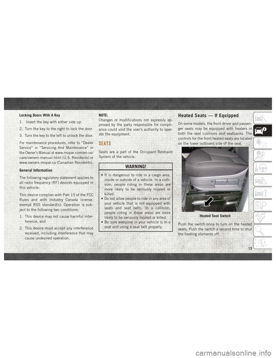
Heated Seats — If Equipped
On some models, the front driver and passen-
ger seats may be equipped with heaters in
both the seat cushions and seatbacks. The
controls for the front heated seats are located
on the lower outboard side of the seat.
Push the switch once to turn on the heated
seats. Push the switch a second time to shut
the heating elements off.
Heated Seat Switch
13
Page 16 of 204
NOTE:
Once a heat setting is selected, heat will be
felt within two to five minutes.
WARNING!
• Persons who are unable to feel pain tothe skin because of advanced age,
chronic illness, diabetes, spinal cord in-
jury, medication, alcohol use, exhaus-
tion or other physical condition must
exercise care when using the seat
heater. It may cause burns even at low
temperatures, especially if used for long
periods of time
• Do not place anything on the seat or
seatback that insulates against heat,
such as a blanket or cushion. This may
cause the seat heater to overheat. Sit-
ting in a seat that has been overheated
could cause serious burns due to the
increased surface temperature of the
seat.
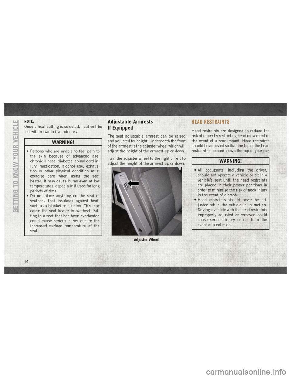
Adjustable Armrests —
If Equipped
The seat adjustable armrest can be raised
and adjusted for height. Underneath the front
of the armrest is the adjuster wheel which will
adjust the height of the armrest up or down.
Turn the adjuster wheel to the right or left to
adjust the height of the armrest up or down.
HEAD RESTRAINTS
Head restraints are designed to reduce the
risk of injury by restricting head movement in
the event of a rear impact. Head restraints
should be adjusted so that the top of the head
restraint is located above the top of your ear.
WARNING!
• All occupants, including the driver,should not operate a vehicle or sit in a
vehicle’s seat until the head restraints
are placed in their proper positions in
order to minimize the risk of neck injury
in the event of a crash.
• Head restraints should never be ad-
justed while the vehicle is in motion.
Driving a vehicle with the head restraints
improperly adjusted or removed could
cause serious injury or death in the
event of a collision.
Adjuster Wheel
GETTING TO KNOW YOUR VEHICLE
14
Page 42 of 204
Yellow Indicator Lights
— Stop Light Failure Indicator Light
This light will illuminate if one or more of the
stop light bulb fails.
The failure relating to this light could be:
• One or more blown bulbs.
• A blown protection fuse.
• A break in the electrical connection.
— External Light Failure Indicator
Light — If Equipped
The External Light Failure Indicator will
come on when a failure to one of the following
lights is detected:
• Direction Indicators
• Backup Lights
• Parking Lights
• Daytime Running Lights
• Clearance Lights
• License Plate Lights The failure relating to these lights could be:
• One or more blown bulbs
• A blown protection fuse
• A break in the electrical connection
— TOW/HAUL Indicator Light
This light will illuminate when TOW/HAUL
mode is selected.
— Glow Plug Light — If Equipped
This vehicle will inhibit engine cranking
when the ambient temperature is less than
–22° F (–30° C) and the oil temperature
sensor reading indicates an engine block
heater has not been used. The Glow Plug
light will flash during in cold weather for up
to ten seconds.
If equipped with a block heater harness the
message "Plug In Engine Heater", will be
displayed in the instrument cluster when the
ambient temperature is below 5°F (-15° C) at
the time the engine is shut off as a reminder
to avoid possible crank delays at the next cold
start.
— Low Diesel Exhaust Fluid (DEF) Indi-
cator Light — If Equipped
The Low Diesel Exhaust Fluid (DEF) Indicator
will illuminate if the vehicle is low on Diesel
Exhaust Fluid (DEF). Refer to “Starting And
Operating” for further information.
— Diesel Particulate Filter (DPF) Indi-
cator Light — If Equipped
When the light illuminates solid, the filter
loading is above the specified range.
GETTING TO KNOW YOUR INSTRUMENT PANEL
40
Page 78 of 204
automatic mode not available). If the en-
gine does not start, contact your authorized
dealer.
Extreme Cold Weather
Your vehicle may be equipped with three
heating elements; one engine block heater (a
resistance heater installed in the water jacket
of the engine) and two transmission heaters
(one resistance heater installed under the oil
reservoir of the hydraulic actuation system
and one on the differential cover of the trans-
mission). To ensure reliable starting/
operating in extreme cold temperatures, use
of an externally powered electric engine
block/transmission heater (available from
your authorized dealer) is recommended.
They require a 110–115 Volt AC electrical
outlet with a grounded, three-wire extension
cord. Their use is recommended for environ-
ments that routinely fall below -10°F
(-23°C). They should be used when the ve-
hicle has not been running overnight or lon-
ger periods and should be plugged in two
hours prior to start. Their use is required for
cold starts with temperatures under -17°F
(-27°C).NOTE:
The engine is designed to work at an ambient
temperature ranging from -22°F to + 122°F
(-30°C to + 50C°). Rubber, pipes, timing belt
cover and electronic devices are not designed
to work out of this range.
In the case of LOW temperature after Start-
ing, the Automated Manual Transmission
may not be able to engage first gear. In this
case a message "Shift not allowed" appears.
In this situation use the engine block heater.
NOTE:
The engine and transmission block heater
cord is a factory installed option. If your
vehicle is not equipped, heater cords are
available from your authorized Mopar dealer.
• A 12 Volt heater built into the fuel filter
housing aids in preventing fuel gelling. It is
controlled by a built-in thermostat.
• A Diesel Pre-Heat system both improves engine starting and reduces the amount of
white smoke generated by a warming
engine.
NORMAL OPERATION
Observe the following when the diesel engine
is operating.
• All message center lights are off.
• Malfunction Indicator Light (MIL) is off.
• Generic Warning Light is off.
• Engine Oil Pressure telltale is notilluminated.
Stopping The Diesel Engine
Idle the engine a few minutes before routine
shutdown. After full load operation, idle the
engine three to five minutes before shutting it
down. This idle period will allow the lubricat-
ing oil and coolant to carry excess heat away
from the combustion chamber, bearings, in-
ternal components, and turbocharger. This is
especially important for turbocharged diesel
engines.
NOTE:
Refer to the following chart for proper engine
shutdown.STARTING AND OPERATING
76
Page 85 of 204

NOTE:
Do not press the brake and accelerator pedals
at the same time. Use only one foot to operate
the brake and accelerator.
To operate in DRIVE (D) (Automatic mode):
• Press and hold the brake pedal.
• Move the gear selector to the DRIVE (D)position.
NOTE:
If the vehicle is moving, DRIVE engagement
will only occur if the vehicle speed is less
than 2 mph (3 km/h). Otherwise, a chime will
sound, the transmission will shift to NEU-
TRAL, and the DRIVE request must then be
repeated by returning the lever to NEUTRAL
and then back into DRIVE once the speed has
been sufficiently reduced.
• To drive, release the brake pedal and press the accelerator pedal.
When in DRIVE (D) the transmission will shift
gears automatically. The Automated Manual
Transmission uses a geartrain and clutch
similar to other manual transmissions. There- fore, you should become familiar with some
of the normal operational characteristics of
the Automated Manual Transmission:
• Engine torque will be interrupted briefly
during the transmission upshifts, making
these shifts more abrupt than with a typical
automatic transmission. This is normal.
• Although transmission shifting is per- formed automatically, the vehicle will not
"creep" when the brake pedal is released,
and may in fact roll down on an incline.
Leaving from a stop, the accelerator pedal
must be pressed to transmit driving torque
to the wheels.
• In Automatic Mode, the Automated Manual Transmission adapts the gear changing
strategy evaluating the road condition such
as slopes in the road.
• During low-speed driving conditions in first gear, vehicle momentum changes may feel
exaggerated in response to changes in ac-
celerator pedal position. This behavior is
normal and is similar to other vehicles
equipped with manual transmissions. • At low speeds you may hear mechanical
noises similar to a manual transmission as
the transmission changes gears. These
noises are normal and will not damage the
transmission.
• Very aggressive driving may result in some clutch odor. A warning message will display
in the instrument cluster display if cool
down actions are needed.
• Before and after the engine is started, you may hear a hydraulic pump for a short
period of time. This noise is normal and will
not damage the transmission.
During extremely cold temperatures, the
transmission will not operate if the oil tem-
perature is -22°F (-30°C) or below. Normal
operation will resume once the transmission
temperature has risen to a suitable level.
When transmission actuation oil temperature
is lower than -22°F (-30°C), engine start will
not be allowed. For this reason the block
heater is recommended below -17°F (-27°C).
83
Page 89 of 204

MESSAGEDESCRIPTION
Press Brake Pedal / Startup Delayed This message appears when the key is first turned ON, if the brake pedal is not depressed and/or the gear selector is not in NEUTRAL (N). The gear selector must be in the NEUTRAL (N) position, and thebrake pedal must be pressed, to allow engine cranking. Place the gear selector in NEUTRAL (N) and
apply the brake pedal BEFORE turning the key to the START/AVV position; otherwise, the engine will not crank and the key must be cycled OFF, then back on, before cranking is allowed.
Gear Unavailable This message appears, along with a warning buzzer:
• When it is not possible to change gear due to a fault in the system.
• When, due a fault in the system, it is only possible to engage 1st (1), 2nd (2), 3rd (3) or REVERSE (R).
Contact your authorized dealer if the message continues to appear.
Shift Not Allowed This message may appear when starting the engine at low temperature. In this case the Automated
Manual transmission isn't able to engage first gear, in this situation either use the engine block/
transmission heater or allow the engine to idle in NEUTRAL (N) until the transmission has warmed.
Press Brake And Try Again This message appears accompanied, in some cases, by a warning buzzer, if you attempt to change gear with the vehicle parked without pressing the brake pedal.
To shift the transmission (with key on/engine off), press and hold the brake pedal, move the gear selec- tor to NEUTRAL (N), then move the gear selector to the desired position.
Shift To Neutral This message appears, when the gear selector must be moved to the NEUTRAL (N) position.
When the gear selector is moved to NEUTRAL (N) the message on the display should go off.
Press Brake Pedal This message is shown in the display together with an acoustic signal, when the brake pedal is not
pressed during a starting attempt.
Press Brake Shift to N key to start This message appears, when the drivers door is first opened, to remind to Press the Brake pedal and shift the lever in N to permit the cranking.
87
Page 105 of 204

Underhood Fuses
The Front Power Distribution Center is lo-
cated on the driver’s side of the engine com-
partment. To access the fuses, remove the
cover.The ID number of the electrical component
corresponding to each fuse can be found on
the back of the cover.
Cavity
Maxi Fuse Mini Fuse Description
F01 40 Amp Orange –Electronic Stability Control (ESC) Pump
F02 20 Amp Yellow (3.6 Gasoline
Engine) –
Starter Relay 3.6L (3.6 Gasoline Engine)
F03 30 Amp Green UREA (3.0 Diesel Engine)
F02 50 Amp Red (3.0 Diesel En-
gine) –
Glow Plug Unit (3.0 Diesel Engine)
F04 50 Amp Red (3.6 Gasoline
Engine) –Secondary Power Distribution Center (PDC) (Trans
Power Relay, Vacuum Pump, KL30 for the Shifter
Transmission Module [STM]) (3.6 Gasoline Engine)
F04 40 Amp Orange (3.0 Diesel
Engine) –
Fuel Filter Heater (3.0 Diesel Engine)
F05 30 Amp Green –SELESPEED Pump RELE (3.0 Diesel Engine) —
If Equipped
F06 40 Amp Orange (non A/C)
60 Amp Blue (A/C) –
Engine Cooling Fan - 2nd Speed
F07 50 Amp Red (non A/C)
60 Amp Blue (A/C) –
Engine Cooling Fan - 1st Speed
F08 40 Amp Orange –Passenger Compartment Blower
F09 –15 Amp BlueRear Power Outlet
103
Page 109 of 204

Right Central Pillar Fuses
The right central pillar fuse panel is located
on the interior side at the base of the passen-
ger side B pillar.
CavityMini Fuse Description
F81 7.5 Amp Brown Seat Heater
F83 20 Amp YellowRear Left Windows Heater
F84 20 Amp YellowRear Right Windows Heater
F86 20 Amp YellowAuxiliary Switch (From Battery) — If Equipped
F87 20 Amp YellowAuxiliary Switch (From Ignition) — If Equipped
107
Page 118 of 204
WARNING!
Do not attempt jump starting if the battery
is frozen. It could rupture or explode and
cause personal injury.
CAUTION!
Do not use a portable battery booster pack
or any other booster source with a system
voltage greater than 12 Volts or damage to
the battery, starter motor, alternator or
electrical system may occur.
Preparations For Jump Start
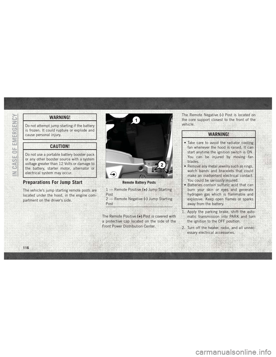
The vehicle’s jump starting remote posts are
located under the hood, in the engine com-
partment on the driver's side.The Remote Positive(+)Post is covered with
a protective cap located on the side of the
Front Power Distribution Center. The Remote Negative
(-)Post is located on
the core support closest to the front of the
vehicle.
WARNING!
• Take care to avoid the radiator cooling fan whenever the hood is raised. It can
start anytime the ignition switch is ON.
You can be injured by moving fan
blades.
• Remove any metal jewelry such as rings,
watch bands and bracelets that could
make an inadvertent electrical contact.
You could be seriously injured.
• Batteries contain sulfuric acid that can
burn your skin or eyes and generate
hydrogen gas which is flammable and
explosive. Keep open flames or sparks
away from the battery.
1. Apply the parking brake, shift the auto- matic transmission into PARK and turn
the ignition to the OFF position.
2. Turn off the heater, radio, and all unnec- essary electrical accessories.
Remote Battery Posts
1 — Remote Positive (+)Jump Starting
Post
2 — Remote Negative (-)Jump Starting
Post
IN CASE OF EMERGENCY
116
Page 120 of 204
3. Disconnect the positive end(+)of the
jumper cable from the positive (+)post of
the booster battery.
4. Disconnect the opposite end of the posi- tive (+)jumper cable from the remote
positive (+)post of the discharged
vehicle.
5. Close the cover of the Front Power Distri- bution Center.
If frequent jump starting is required to start
your vehicle you should have the battery and
charging system inspected at your authorized
dealer.
CAUTION!
Accessories plugged into the vehicle
power outlets draw power from the vehi-
cle’s battery, even when not in use (i.e.,
cellular devices, etc.). Eventually, if
plugged in long enough without engine
operation, the vehicle’s battery will dis-
charge sufficiently to degrade battery life
and/or prevent the engine from starting.
Battery Location
There are two remote jump starting posts
under the hood which is the recommended
jump start location. If access to the battery is
needed, an access panel on the driver’s side
floor will allow for battery access.
IF YOUR ENGINE OVERHEATS
In any of the following situations, you can
reduce the potential for overheating by taking
the appropriate action.
• On the highways — slow down.
• In city traffic — while stopped, place the transmission in NEUTRAL, but do not in-
crease the engine idle speed while prevent-
ing vehicle motion with the brakes.
NOTE:
There are steps that you can take to slow
down an impending overheat condition:
• If your air conditioner (A/C) is on, turn it off. The A/C system adds heat to the engine
cooling system and turning the A/C off can
help remove this heat. • You can also turn the temperature control
to maximum heat, the mode control to floor
and the blower control to high. This allows
the heater core to act as a supplement to
the radiator and aids in removing heat from
the engine cooling system.
WARNING!
You or others can be badly burned by hot
engine coolant (antifreeze) or steam from
your radiator. If you see or hear steam
coming from under the hood, do not open
the hood until the radiator has had time to
cool. Never try to open a cooling system
pressure cap when the radiator or coolant
bottle is hot.
IN CASE OF EMERGENCY
118