instrument panel Ram ProMaster 2018 User Guide
[x] Cancel search | Manufacturer: RAM, Model Year: 2018, Model line: ProMaster, Model: Ram ProMaster 2018Pages: 204, PDF Size: 4 MB
Page 7 of 204
GRAPHICAL TABLE OF CONTENTS
GETTING TO KNOW YOUR VEHICLE
GETTING TO KNOW YOUR INSTRUMENT PANEL SAFETY
STARTING AND OPERATING IN CASE OF EMERGENCY
SERVICING AND MAINTENANCE TECHNICAL SPECIFICATIONS MULTIMEDIA
CUSTOMER ASSISTANCE INDEX
Page 9 of 204
GRAPHICAL TABLE OF CONTENTS
INSTRUMENT PANEL.............8
INTERIOR .....................9
GRAPHICAL TABLE OF CONTENTS
7
Page 10 of 204
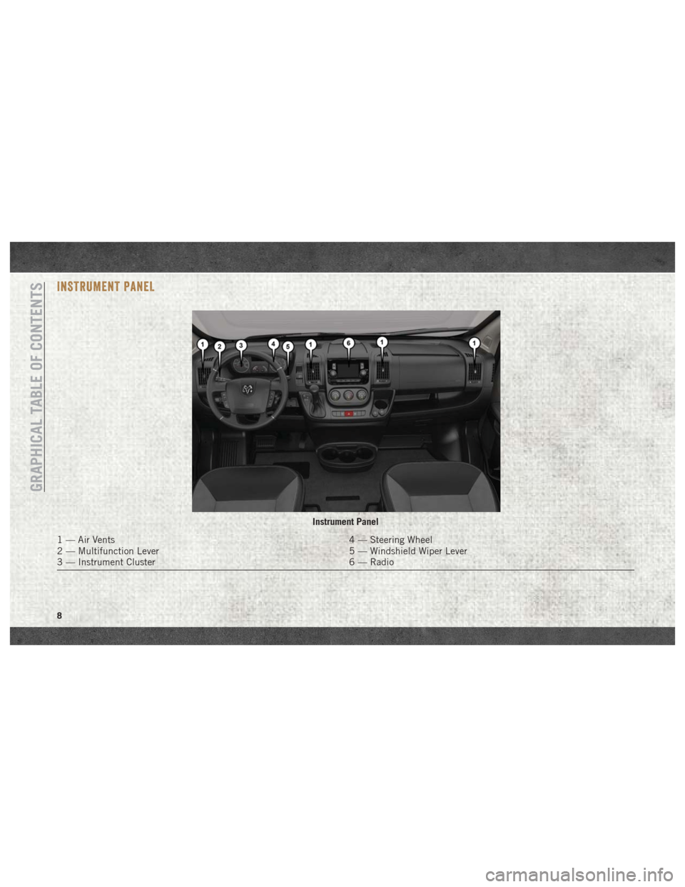
INSTRUMENT PANEL
Instrument Panel
1 — Air Vents4 — Steering Wheel
2 — Multifunction Lever 5 — Windshield Wiper Lever
3 — Instrument Cluster 6 — Radio
GRAPHICAL TABLE OF CONTENTS
8
Page 19 of 204
Headlights
To turn on the headlights, turn the end of the
multifunction lever to the headlight position.
When the headlight switch is on, the parking
lights, taillights, license plate light, the clear-
ance lights and instrument panel lights are
also turned on. To turn off the headlights,
turn the end of the multifunction lever back
to the O (Off) position.
High Beam/Low Beam Select
Switch
Pull the multifunction lever toward you to
switch the headlights to high beam. Pull the
lever a second time to switch the headlights
back to low beam.
Parking Lights
These lights can only be turned on with igni-
tion key in the STOP position or removed, by
moving the end of the multifunction lever to
O (off) position and then to the headlight
position.The warning light telltale in the instrument
panel comes on. The lights stay on until the
next ignition cycle is performed.
Turn Signals
Move the multifunction lever up or down and
the arrows on each side of the instrument
cluster flash to show proper operation of the
front and rear turn signal lights.
NOTE:
If either light remains on and does not flash,
or there is a very fast flash rate, check for a
defective outside light bulb. If an indicator
fails to light when the lever is moved, it would
suggest that the indicator bulb is defective.
Lane Change Assist
Tap the lever up or down once, without mov-
ing beyond the detent, and the turn signal
(right or left) will flash five times then auto-
matically turn off.
INTERIOR LIGHTS
The courtesy lights, dome lights, and map
lights are mounted between the sun visors on
the overhead shelf. Each light is turned on by
pushing the corresponding switch.
The courtesy lights will turn on when you use
the key fob or manually from the driver door
cylinder to unlock the doors or open any door.
The lights will fade to off after approximately
30 seconds, or they will immediately fade to
off once the ignition switch is turned to ON/
RUN from the OFF position.
WIPERS AND WASHERS
Front Wiper Operation
The windshield wiper/washer lever is located
on the right side of the steering column.
There are five different modes of operation
for the front windshield wipers. The wind-
shield wiper lever can be raised or lowered to
access the modes.
17
Page 21 of 204
CLIMATE CONTROLS
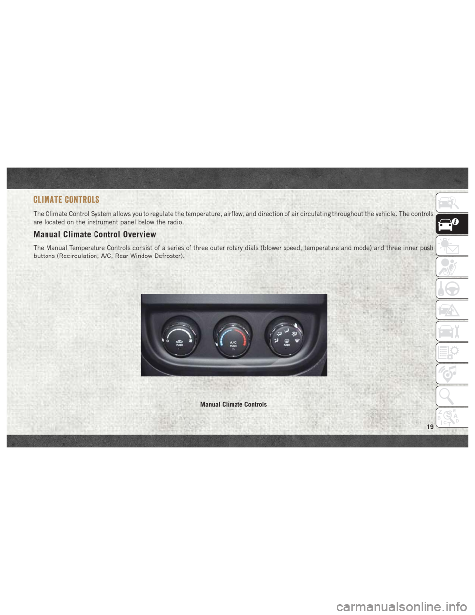
The Climate Control System allows you to regulate the temperature, airflow, and direction of air circulating throughout the vehicle. The controls
are located on the instrument panel below the radio.
Manual Climate Control Overview
The Manual Temperature Controls consist of a series of three outer rotary dials (blower speed, temperature and mode) and three inner push
buttons (Recirculation, A/C, Rear Window Defroster).
Manual Climate Controls
19
Page 23 of 204
IconDescription
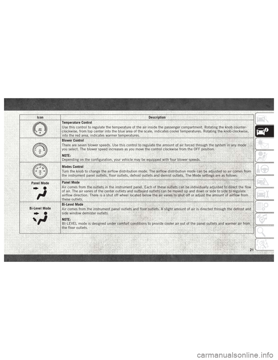
Temperature Control
Use this control to regulate the temperature of the air inside the passenger compartment. Rotating the knob counter-
clockwise, from top center into the blue area of the scale, indicates cooler temperatures. Rotating the knob clockwise,
into the red area, indicates warmer temperatures.
Blower Control
There are seven blower speeds. Use this control to regulate the amount of air forced through the system in any mode
you select. The blower speed increases as you move the control clockwise from the OFF position.
NOTE:
Depending on the configuration, your vehicle may be equipped with four blower speeds.
Modes Control
Turn the knob to change the airflow distribution mode. The airflow distribution mode can be adjusted so air comes from
the instrument panel outlets, floor outlets, defrost outlets and demist outlets. The Mode settings are as follows:
Panel Mode
Panel Mode
Air comes from the outlets in the instrument panel. Each of these outlets can be individually adjusted to direct the flow
of air. The air vanes of the center outlets and outboard outlets can be moved up and down or side to side to regulate
airflow direction. There is a shut off wheel located below the air vanes to shut off or adjust the amount of airflow from
these outlets.
Bi-Level Mode
Bi-Level Mode
Air comes from the instrument panel outlets and floor outlets. A slight amount of air is directed through the defrost and
side window demister outlets.
NOTE:
BI-LEVEL mode is designed under comfort conditions to provide cooler air out of the panel outlets and warmer air from
the floor outlets.
21
Page 24 of 204
IconDescription
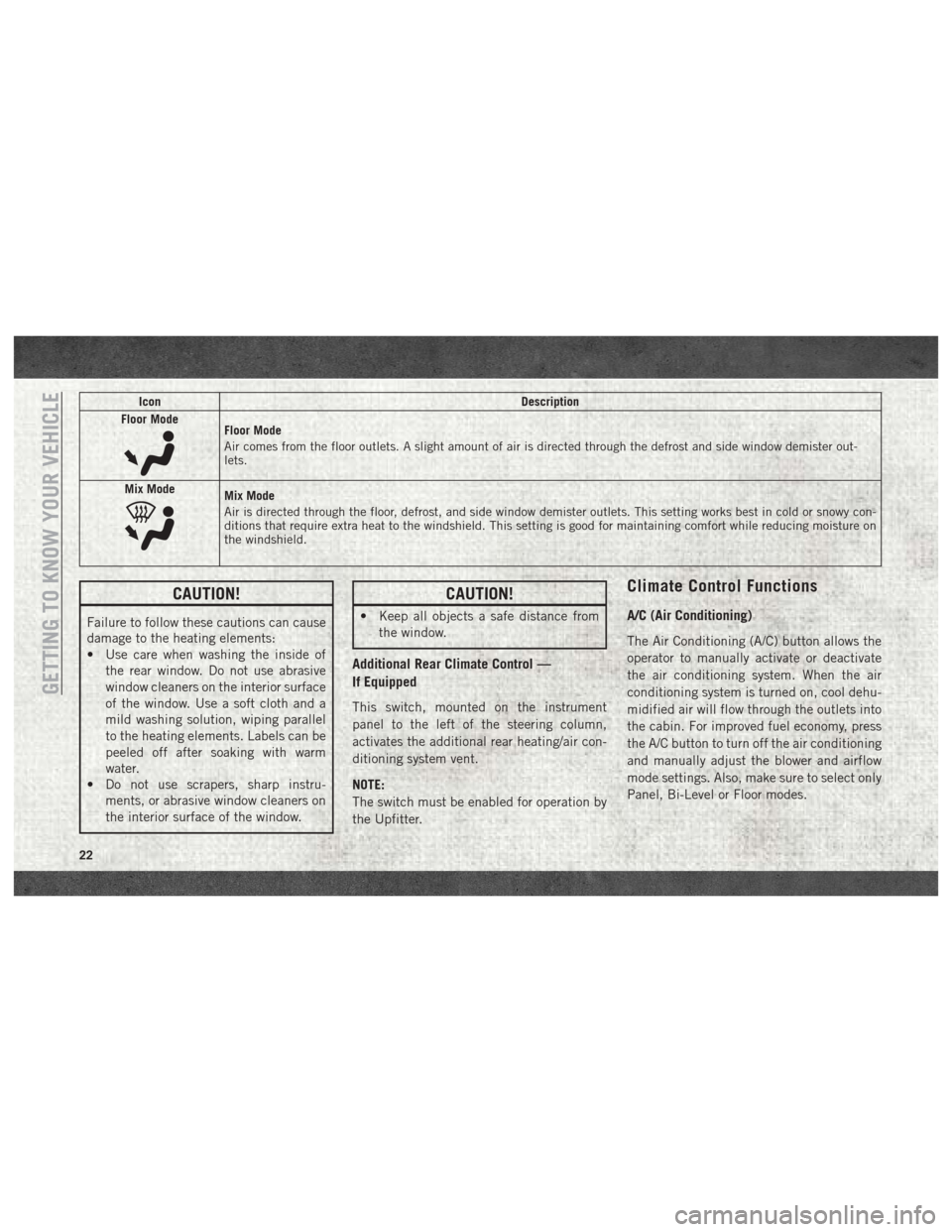
Floor Mode
Floor Mode
Air comes from the floor outlets. A slight amount of air is directed through the defrost and side window demister out-
lets.
Mix Mode
Mix Mode
Air is directed through the floor, defrost, and side window demister outlets. This setting works best in cold or snowy con-
ditions that require extra heat to the windshield. This setting is good for maintaining comfort while reducing moisture on
the windshield.
CAUTION!
Failure to follow these cautions can cause
damage to the heating elements:
• Use care when washing the inside of the rear window. Do not use abrasive
window cleaners on the interior surface
of the window. Use a soft cloth and a
mild washing solution, wiping parallel
to the heating elements. Labels can be
peeled off after soaking with warm
water.
• Do not use scrapers, sharp instru-
ments, or abrasive window cleaners on
the interior surface of the window.
CAUTION!
• Keep all objects a safe distance fromthe window.
Additional Rear Climate Control —
If Equipped
This switch, mounted on the instrument
panel to the left of the steering column,
activates the additional rear heating/air con-
ditioning system vent.
NOTE:
The switch must be enabled for operation by
the Upfitter.
Climate Control Functions
A/C (Air Conditioning)
The Air Conditioning (A/C) button allows the
operator to manually activate or deactivate
the air conditioning system. When the air
conditioning system is turned on, cool dehu-
midified air will flow through the outlets into
the cabin. For improved fuel economy, press
the A/C button to turn off the air conditioning
and manually adjust the blower and airflow
mode settings. Also, make sure to select only
Panel, Bi-Level or Floor modes.
GETTING TO KNOW YOUR VEHICLE
22
Page 26 of 204
NOTE:
Recirculate without A/C should not be used
for long periods, as fogging may occur.
Outside Air Intake
Make sure the air intake, located directly in
front of the windshield, is free of obstructions
such as leaves. Leaves collected in the air
intake may reduce airflow, and if they enter
the plenum, they could plug the water drains.
In winter months, make sure the air intake is
clear of ice, slush, and snow.
A/C Air Filter
The climate control system filters outside air
containing dust, pollen and some odors. Strong
odors cannot be totally filtered out.
Refer to
“Dealer Service” in “Servicing and Maintenance”
in your Owner’s Manual on
www.mopar.com/
en-us/care/owners-manual.html
(U.S. Resi-
dents) or www.owners.mopar.ca (Canadian
Residents) for filter replacement instruc-
tions.
HOOD
Opening
To open the hood, two latches must be re-
leased.
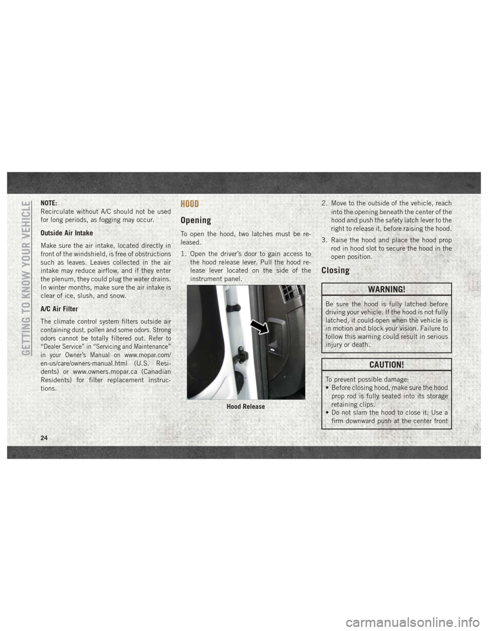
1. Open the driver’s door to gain access to the hood release lever. Pull the hood re-
lease lever located on the side of the
instrument panel. 2. Move to the outside of the vehicle, reach
into the opening beneath the center of the
hood and push the safety latch lever to the
right to release it, before raising the hood.
3. Raise the hood and place the hood prop rod in hood slot to secure the hood in the
open position.
Closing
WARNING!
Be sure the hood is fully latched before
driving your vehicle. If the hood is not fully
latched, it could open when the vehicle is
in motion and block your vision. Failure to
follow this warning could result in serious
injury or death.
CAUTION!
To prevent possible damage:
• Before closing hood, make sure the hoodprop rod is fully seated into its storage
retaining clips.
• Do not slam the hood to close it. Use a
firm downward push at the center front
Hood Release
GETTING TO KNOW YOUR VEHICLE
24
Page 31 of 204
GETTING TO KNOW YOUR INSTRUMENT PANEL
INSTRUMENT CLUSTER DISPLAY.....30
Location And Controls............30
Diesel Messages — If Equipped ......31
WARNING LIGHTS AND MESSAGES ....34
Red Warning Lights..............34 Yellow Warning Lights
............37
Yellow Indicator Lights ............40
Green Indicator Lights ............41
Blue Indicator Lights .............41
ONBOARD DIAGNOSTIC SYSTEM —
OBDII .....................42
Onboard Diagnostic System (OBD II)
Cybersecurity.................42
GETTING TO KNOW YOUR INSTRUMENT PANEL
29
Page 32 of 204
INSTRUMENT CLUSTER DISPLAY
Your vehicle may be equipped with an instru-
ment cluster display, which offers useful in-
formation to the driver. With the ignition in
the STOP/OFF mode, opening/closing of a
door will activate the display for viewing, and
display the total miles, or kilometers, in the
odometer. Your instrument cluster display is
designed to display important information
about your vehicle’s systems and features.
Using a driver interactive display located on
the instrument panel, your instrument clus-
ter display can show you how systems are
working and give you warnings when they are
not. The steering wheel mounted controls
allow you to scroll through the main menus
and submenus. You can access the specific
information you want and make selections
and adjustments.
Location And Controls
The instrument cluster display features a
driver-interactive display that is located in
the instrument cluster.This system allows the driver to select a
variety of useful information by pushing the
switches mounted on the instrument panel.
Examples of menu items are:
• Speed Beep
• Buzzer Volume
• Seat Belt Buzzer (Just Available After SBR
Disable Made By CHR Service)
• Service (Diesel Only)
• Exit Menu
If equipped with a Uconnect system, some
customer programmable features will
display in the radio. Refer to the “Uconnect
Settings” in “Multimedia” in the Owner’s
Manual at
www.mopar.com/en-us/care/
owners-manual.html (U.S. Residents) or
www.owners.mopar.ca (Canadian Residents)
for further information.
The system allows the driver to select infor-
mation by pushing the following buttons
mounted on the instrument panel to the left
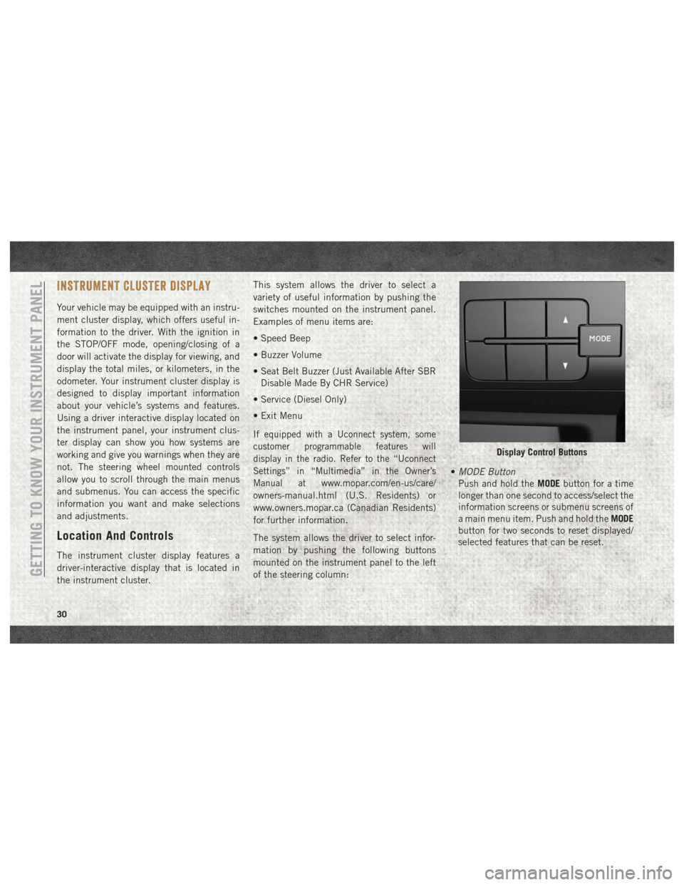
of the steering column: •
MODE Button
Push and hold the MODEbutton for a time
longer than one second to access/select the
information screens or submenu screens of
a main menu item. Push and hold the MODE
button for two seconds to reset displayed/
selected features that can be reset.
Display Control Buttons
GETTING TO KNOW YOUR INSTRUMENT PANEL
30