ESP Ram ProMaster 2019 Owner's Manual
[x] Cancel search | Manufacturer: RAM, Model Year: 2019, Model line: ProMaster, Model: Ram ProMaster 2019Pages: 332, PDF Size: 3.66 MB
Page 2 of 332

VEHICLES SOLD IN CANADA
With respect to any Vehicles Sold in Canada, the name
FCA US LLC shall be deemed to be deleted and the name
FCA Canada Inc. used in substitution therefore.
DRIVING AND ALCOHOL
Drunken driving is one of the most frequent causes of
accidents.
Your driving ability can be seriously impaired with blood
alcohol levels far below the legal minimum. If you are
drinking, don’t drive. Ride with a designated non-
drinking driver, call a cab, a friend, or use public trans-
portation.
WARNING!
Driving after drinking can lead to an accident.
Your perceptions are less sharp, your reflexes are
slower, and your judgment is impaired when you
have been drinking. Never drink and then drive.
This manual illustrates and describes the operation of
features and equipment that are either standard or op-
tional on this vehicle. This manual may also include a
description of features and equipment that are no longer
available or were not ordered on this vehicle. Please
disregard any features and equipment described in this
manual that are not on this vehicle.
FCA US LLC reserves the right to make changes in design
and specifications, and/or make additions to or improve-
ments to its products without imposing any obligation
upon itself to install them on products previously manu-
factured.
Copyright © 2018 FCA US LLC
Page 20 of 332
The recommended replacement battery is CR2032.
1. Push the mechanical key release button and release themechanical key to access the battery case screw located
on the side of the key fob.
2. Rotate the screw located on the side of the key fob using a small screwdriver.
3. Take out the battery case. Remove and replace the battery observing its polarity.
4. Refit the battery case inside the key fob and turn the screw to lock it into place.Programming Additional Key Fobs
Programming the key fob may be performed by an autho-
rized dealer.
General Information
The following regulatory statement applies to all radio
frequency (RF) devices equipped in this vehicle:
This device complies with Part 15 of the FCC Rules and
with Industry Canada license-exempt RSS standard(s).
Operation is subject to the following two conditions:
1. This device may not cause harmful interference, and
2. This device must accept any interference received, in-cluding interference that may cause undesired opera-
tion.
NOTE: Changes or modifications not expressly approved
by the party responsible for compliance could void the
user ’s authority to operate the equipment.
IGNITION SWITCH
Mechanical Ignition Switch
1. Place the gear selector in PARK (if equipped with an automatic transmission).
Key Fob Screw Location
18 GETTING TO KNOW YOUR VEHICLE
Page 23 of 332
General Information
The following regulatory statement applies to all radio
frequency (RF) devices equipped in this vehicle:
This device complies with Part 15 of the FCC Rules and
with Industry Canada license-exempt RSS standard(s).
Operation is subject to the following two conditions:
1. This device may not cause harmful interference, and
2. This device must accept any interference received, in-cluding interference that may cause undesired opera-
tion.
NOTE: Changes or modifications not expressly approved
by the party responsible for compliance could void the
user ’s authority to operate the equipment.
VEHICLE SECURITY ALARM — IF EQUIPPED
The vehicle security alarm monitors the vehicle doors and
ignition for unauthorized operation. When the vehicle
security alarm is activated, interior switches for door locks
are disabled. The system provides both audible and visible
signals. For the first three minutes, the horn will sound,
and the turn signal lights will flash. For an additional 15
minutes, only the turn signal lights will flash.
To Arm The System
To arm the system, the vehicle security alarm will set when
you use the key fob to lock the doors. If a door or the hood
is not properly shut, the alarm system will not be armed.
To Disarm The System
Use the key fob to unlock the door and disarm the system.
The vehicle security alarm will also disarm if a pro-
grammed Sentry Key is inserted into the ignition switch. To
exit the alarming mode, push the key fob unlock button, or
insert a programmed Sentry Key into the ignition switch.
The vehicle security alarm is designed to protect your
vehicle. However, you can create conditions where the
system will give you a false alarm. If one of the previously
described arming sequences has occurred, the vehicle
security alarm will arm regardless of whether you are in
the vehicle or not. If you remain in the vehicle and open a
door, the alarm will sound. If this occurs, disarm the
vehicle security alarm.
Rearming Of The System
If the system has not been disabled, the vehicle security
alarm will rearm itself after the 15 additional minutes of
turn lamps flashing. If the condition which initiated the
3
GETTING TO KNOW YOUR VEHICLE 21
Page 32 of 332
WARNING!
•Persons who are unable to feel pain to the skin
because of advanced age, chronic illness, diabetes,
spinal cord injury, medication, alcohol use, exhaus-
tion or other physical condition must exercise care
when using the seat heater. It may cause burns even
at low temperatures, especially if used for long
periods of time.
• Do not place anything on the seat or seatback that
insulates against heat, such as a blanket or cushion.
This may cause the seat heater to overheat. Sitting in
a seat that has been overheated could cause serious
burns due to the increased surface temperature of the
seat.
Fold Down Tray — If Equipped
If your vehicle is equipped with a bench seat, the seat is
equipped with a fold-down tray that can be used as a
document support surface. To use the fold-down tray,
grasp the pull tab and lower the tray.
Fold-Down Pull Tab
30 GETTING TO KNOW YOUR VEHICLE
Page 42 of 332
Flash-To-Pass
You can signal another vehicle with your headlights by
partially pulling the multifunction lever toward the steer-
ing wheel. This will cause the high beam headlights to turn
on until the lever is released.
Parking Lights
These lights can only be turned on with ignition key in the
STOP position or removed, by moving the end of the
multifunction lever to O (off) position and then to the
headlight position.
The warning light telltale in the instrument panel comes
on. The lights stay on until the next ignition cycle is
performed.
Follow Me Home/Headlight Delay
When this feature is selected, the driver can choose to have
the headlights remain on for a preset period of time.
Activation
Remove the key or turn the ignition to the OFF/LOCK
position, and pull the multifunction lever toward the
steering wheel, within two minutes. Each time the lever ispulled, the activation of the lights will be extended by 30
seconds. The activation of the lights can be extended to a
maximum of 210 seconds.
The warning light on the instrument panel will light up
and the corresponding message will appear in the instru-
ment cluster display for as long as the function is activated.
The warning light comes on when the lever is operated and
stays on until the function is automatically deactivated.
Each movement of the lever only increases the amount of
time the lights stay on.
Deactivation
Pull the multifunction lever toward the steering wheel and
hold it for more than two seconds.
Fog Lights — If Equipped
The fog light switch is located on the center stack of the
instrument panel, just below the climate controls. Push the
switch once to turn the fog lights on. Push the switch a
second time to turn the fog lights off.
NOTE:
If the vehicle’s ignition is turned OFF, the fog lights
will also turn off.
40 GETTING TO KNOW YOUR VEHICLE
Page 43 of 332
Turn Signals
Move the multifunction lever up or down and the arrows
on each side of the instrument cluster flash to show proper
operation of the front and rear turn signal lights.
NOTE:If either light remains on and does not flash, or
there is a very fast flash rate, check for a defective outside
light bulb. If an indicator fails to light when the lever is
moved, it would suggest that the indicator bulb is defec-
tive.
Lane Change Assist
Tap the lever up or down once, without moving beyond
the detent, and the turn signal (right or left) will flash five
times then automatically turn off.
Battery Saver
To protect the life of your vehicle’s battery when the
ignition is OFF and any door is left ajar for 15 minutes the
interior lights will automatically turn off.
NOTE: Battery saver mode is cancelled if the ignition is
ON.
INTERIOR LIGHTS
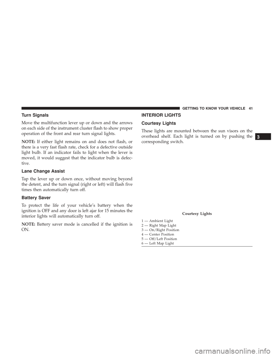
Courtesy Lights
These lights are mounted between the sun visors on the
overhead shelf. Each light is turned on by pushing the
corresponding switch.
Courtesy Lights
1 — Ambient Light
2 — Right Map Light
3 — On/Right Position
4 — Center Position
5 — Off/Left Position
6 — Left Map Light
3
GETTING TO KNOW YOUR VEHICLE 41
Page 79 of 332
The light also will turn on when the parking brake is
applied with the ignition switch in the ON/RUN position.
NOTE:This light shows only that the parking brake is
applied. It does not show the degree of brake application.
— Oil Pressure Warning Light
This warning light will illuminate to indicate low engine
oil pressure. If the light turns on while driving, stop the
vehicle, shut off the engine as soon as possible, and contact
an authorized dealer. A chime will sound when this light
turns on.
Do not operate the vehicle until the cause is corrected. This
light does not indicate how much oil is in the engine. The
engine oil level must be checked under the hood.
— Vehicle Security Warning Light — If Equipped
This light will flash at a fast rate for approximately 15
seconds when the vehicle security alarm is arming, and
then will flash slowly until the vehicle is disarmed.
Yellow Warning Lights
— Immobilizer Fail / VPS Electrical Alarm
Indicator Light
This telltale will illuminate when the vehicle security alarm
system has detected an attempt to break into the vehicle.
NOTE: After cycling the ignition to the ON/RUN posi-
tion, the Vehicle Security Warning Light could illuminate if
a problem with the system is detected. This condition will
result in the engine being shut off after two seconds.
— Tire Pressure Monitoring System (TPMS)
Warning Light
The warning light switches on and a message is displayed
to indicate that the tire pressure is lower than the recom-
mended value and/or that slow pressure loss is occurring.
In these cases, optimal tire duration and fuel consumption
may not be guaranteed.
Should one or more tires be in the condition mentioned
above, the display will show the indications corresponding
to each tire.
4
GETTING TO KNOW YOUR INSTRUMENT PANEL 77
Page 80 of 332

CAUTION!
Do not continue driving with one or more flat tires as
handling may be compromised. Stop the vehicle,
avoiding sharp braking and steering. If a tire puncture
occurs, repair immediately using the dedicated tire
repair kit and contact an authorized dealer as soon as
possible.
Each tire, including the spare (if provided), should be
checked monthly when cold and inflated to the inflation
pressure recommended by the vehicle manufacturer on the
vehicle placard or tire inflation pressure label. (If your
vehicle has tires of a different size than the size indicated
on the vehicle placard or tire inflation pressure label, you
should determine the proper tire inflation pressure for
those tires.)
As an added safety feature, your vehicle has been
equipped with a Tire Pressure Monitoring System (TPMS)
that illuminates a low tire pressure telltale when one or
more of your tires is significantly under-inflated. Accord-
ingly, when the low tire pressure telltale illuminates, you
should stop and check your tires as soon as possible, and
inflate them to the proper pressure. Driving on a signifi-
cantly under-inflated tire causes the tire to overheat and can lead to tire failure. Under-inflation also reduces fuel
efficiency and tire tread life, and may affect the vehicle’s
handling and stopping ability.
Please note that the TPMS is not a substitute for proper tire
maintenance, and it is the driver ’s responsibility to main-
tain correct tire pressure, even if under-inflation has not
reached the level to trigger illumination of the TPMS low
tire pressure telltale.
Your vehicle has also been equipped with a TPMS malfunc-
tion indicator to indicate when the system is not operating
properly. The TPMS malfunction indicator is combined
with the low tire pressure telltale. When the system detects
a malfunction, the telltale will flash for approximately one
minute and then remain continuously illuminated. This
sequence will continue upon subsequent vehicle start-ups
as long as the malfunction exists. When the malfunction
indicator is illuminated, the system may not be able to
detect or signal low tire pressure as intended. TPMS
malfunctions may occur for a variety of reasons, including
the installation of replacement or alternate tires or wheels
on the vehicle that prevent the TPMS from functioning
properly. Always check the TPMS malfunction telltale after
replacing one or more tires or wheels on your vehicle to
78 GETTING TO KNOW YOUR INSTRUMENT PANEL
Page 97 of 332
HSA Activation Criteria
The following criteria must be met in order for HSA to
activate:
•Vehicle must be stopped.
• Vehicle must be on a 6% (approximate) grade or greater
hill.
• Gear selection matches vehicle uphill direction (i.e.,
vehicle facing uphill is in forward gear; vehicle backing
uphill is in REVERSE gear).
HSA will work in REVERSE and all forward gears when
the activation criteria have been met. The system will not
activate if the vehicle is placed in NEUTRAL or PARK.
WARNING!
There may be situations on minor hills with a loaded
vehicle, or while pulling a trailer, when the system will
not activate and slight rolling may occur. This could
cause a collision with another vehicle or object. Always
remember the driver is responsible for braking the
vehicle.
AUXILIARY DRIVING SYSTEMS
Tire Pressure Monitoring System (TPMS)
The Tire Pressure Monitor System (TPMS) will warn the
driver of a low tire pressure based on the vehicle recom-
mended cold placard pressure.
The tire pressure will vary with temperature by about 1 psi
(7 kPa) for every 12°F (6.5°C). This means that when the
outside temperature decreases, the tire pressure will de-
crease. Tire pressure should always be set based on cold
inflation tire pressure. This is defined as the tire pressure
after the vehicle has not been driven for at least three
hours, or driven less than 1 mile (1.6 km) after a three hour
period. The cold tire inflation pressure must not exceed the
maximum inflation pressure molded into the tire sidewall.
Refer to “Tires” in “Servicing And Maintenance” for infor-
mation on how to properly inflate the vehicle’s tires. The
tire pressure will also increase as the vehicle is driven - this
is normal and there should be no adjustment for this
increased pressure.
The TPMS will warn the driver of a low tire pressure if the
tire pressure falls below the low-pressure warning limit for
any reason, including low temperature effects and natural
pressure loss through the tire.
5
SAFETY 95
Page 99 of 332
NOTE:
•The TPMS is not intended to replace normal tire care and
maintenance or to provide warning of a tire failure or
condition.
• The TPMS should not be used as a tire pressure gauge
while adjusting your tire pressure.
• Driving on a significantly under-inflated tire causes the
tire to overheat and can lead to tire failure. Under-
inflation also reduces fuel efficiency and tire tread life,
and may affect the vehicle’s handling and stopping
ability.
• The TPMS is not a substitute for proper tire mainte-
nance, and it is the driver ’s responsibility to maintain
correct tire pressure using an accurate tire pressure
gauge, even if under-inflation has not reached the level
to trigger illumination of the TPMS Warning Light.
• Seasonal temperature changes will affect tire pressure,
and the TPMS will monitor the actual tire pressure in the
tire.Base System
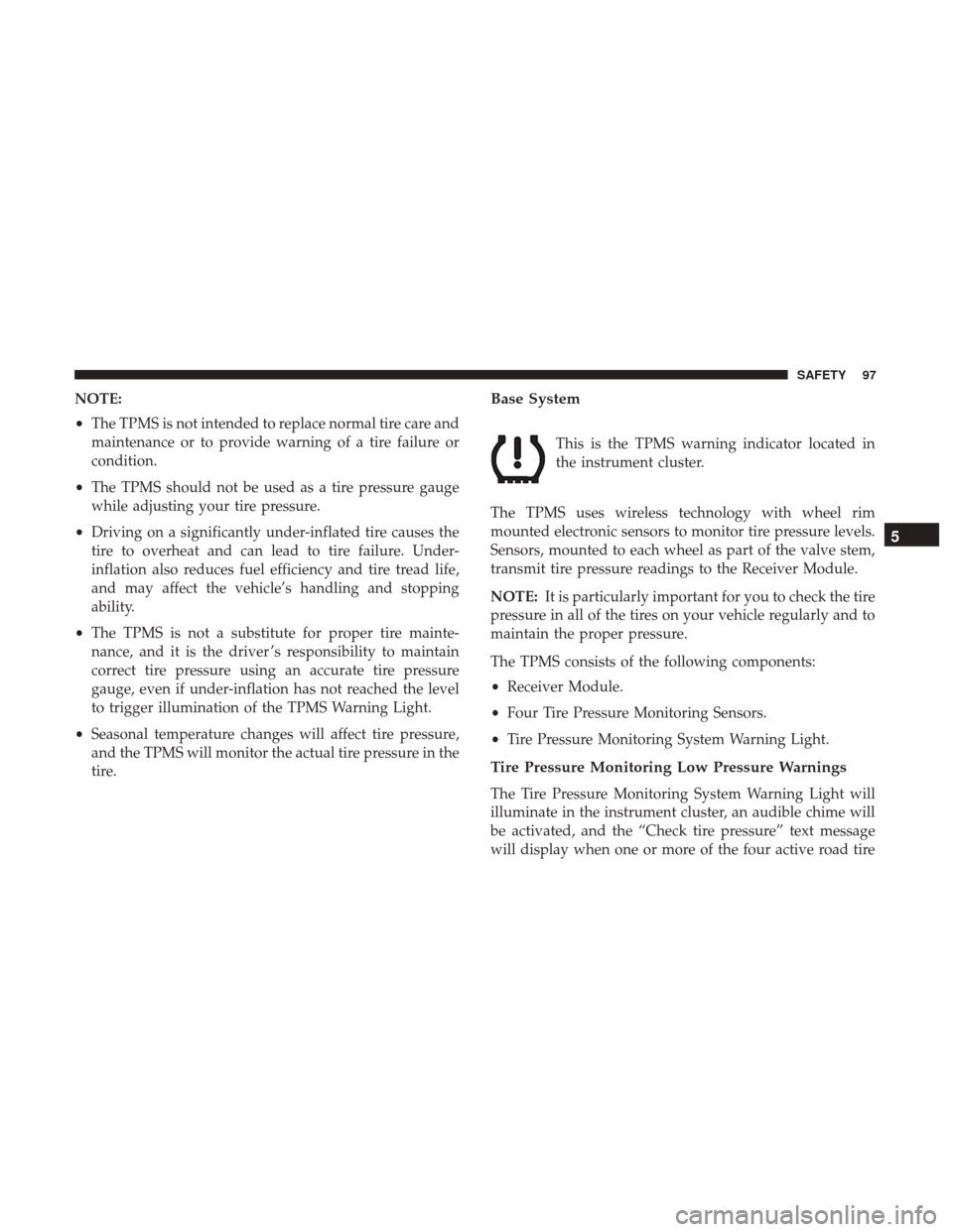
This is the TPMS warning indicator located in
the instrument cluster.
The TPMS uses wireless technology with wheel rim
mounted electronic sensors to monitor tire pressure levels.
Sensors, mounted to each wheel as part of the valve stem,
transmit tire pressure readings to the Receiver Module.
NOTE: It is particularly important for you to check the tire
pressure in all of the tires on your vehicle regularly and to
maintain the proper pressure.
The TPMS consists of the following components:
• Receiver Module.
• Four Tire Pressure Monitoring Sensors.
• Tire Pressure Monitoring System Warning Light.
Tire Pressure Monitoring Low Pressure Warnings
The Tire Pressure Monitoring System Warning Light will
illuminate in the instrument cluster, an audible chime will
be activated, and the “Check tire pressure” text message
will display when one or more of the four active road tire
5
SAFETY 97