ECO mode Ram ProMaster 2020 Owner's Guide
[x] Cancel search | Manufacturer: RAM, Model Year: 2020, Model line: ProMaster, Model: Ram ProMaster 2020Pages: 264, PDF Size: 10.11 MB
Page 111 of 264
STARTING AND OPERATING109
If it’s necessary to keep the ball mount and
hitch ball assembly mounted for a long period,
it is possible to filter out the ball mount and
hitch ball assembly presence in sensor field of
view. The filtering operation must be performed
only by an authorized dealer.
PARKVIEW REAR BACK UP CAMERA
Your vehicle is equipped with the ParkView Rear
Back Up Camera that allows you to see an
on-screen image of the rear surroundings of
your vehicle whenever the gear selector is put
into REVERSE and/or when the rear doors are opened. The image will be displayed on the
touchscreen display along with a caution note
to “check entire surroundings” across the top of
the screen. After five seconds this note will
disappear. The ParkView Rear Back Up Camera
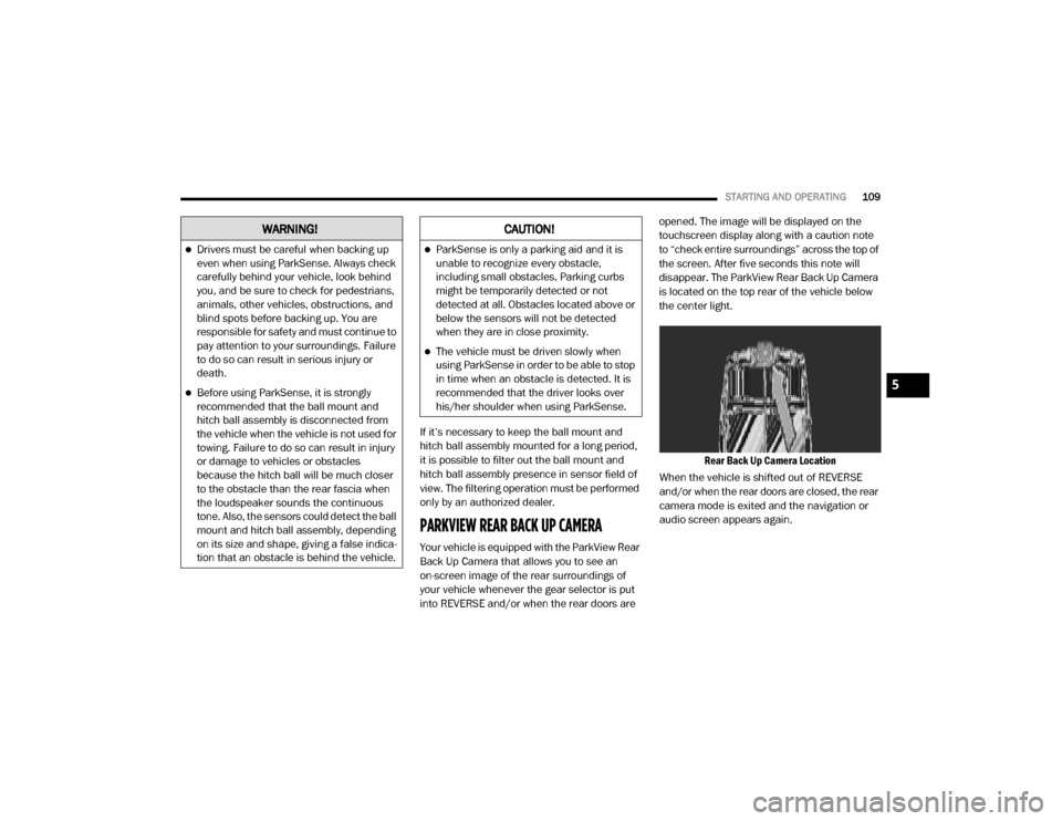
is located on the top rear of the vehicle below
the center light.
Rear Back Up Camera Location
When the vehicle is shifted out of REVERSE
and/or when the rear doors are closed, the rear
camera mode is exited and the navigation or
audio screen appears again.
WARNING!
Drivers must be careful when backing up
even when using ParkSense. Always check
carefully behind your vehicle, look behind
you, and be sure to check for pedestrians,
animals, other vehicles, obstructions, and
blind spots before backing up. You are
responsible for safety and must continue to
pay attention to your surroundings. Failure
to do so can result in serious injury or
death.
Before using ParkSense, it is strongly
recommended that the ball mount and
hitch ball assembly is disconnected from
the vehicle when the vehicle is not used for
towing. Failure to do so can result in injury
or damage to vehicles or obstacles
because the hitch ball will be much closer
to the obstacle than the rear fascia when
the loudspeaker sounds the continuous
tone. Also, the sensors could detect the ball
mount and hitch ball assembly, depending
on its size and shape, giving a false indica -
tion that an obstacle is behind the vehicle.
CAUTION!
ParkSense is only a parking aid and it is
unable to recognize every obstacle,
including small obstacles. Parking curbs
might be temporarily detected or not
detected at all. Obstacles located above or
below the sensors will not be detected
when they are in close proximity.
The vehicle must be driven slowly when
using ParkSense in order to be able to stop
in time when an obstacle is detected. It is
recommended that the driver looks over
his/her shoulder when using ParkSense.
5
20_VF_OM_EN_US_t.book Page 109
Page 142 of 264

140IN CASE OF EMERGENCY
Tire Service Kit Components And Operation
Tire Service Kit Components
Using The Mode Select Knob And Hoses
Your Tire Service Kit is equipped with the
following symbols to indicate the air or sealant
mode.
Selecting Air Mode
Push in the Mode Select Knob (2)
and turn to this position for air
pump operation only. Use the Black
Air Pump Hose (5) when selecting
this mode.
Selecting Sealant Mode
Push in the Mode Select Knob (2)
and turn to this position to inject
the Tire Service Kit Sealant and to
inflate the tire. Use the Sealant
Hose (3) when selecting this mode.
Using The Power Button
Push and release the Power Button
(1) once to turn on the Tire Service
Kit. Push and release the Power
Button (1) again to turn Off the Tire
Service Kit.
Using The Deflation Button
Push the Deflation Button (9) to
reduce the air pressure in the tire if
it becomes over-inflated.
Tire Service Kit Usage Precautions
Replace the Tire Service Kit Sealant Bottle
(4) and Sealant Hose (3) prior to the expira -
tion date (printed at the upper right hand
corner on the bottle label) to assure optimum
operation of the system. Refer to “Sealing A
Tire With Tire Service Kit” section (F) “Sealant
Bottle And Hose Replacement in this section
for further information”.
Tire Service Kit Sealant Expiration Date Location
1 — Power Button
2 — Mode Select Knob
3 — Sealant Hose (Clear)
4 — Sealant Bottle
5 — Air Pump Hose (Black)
6 — Sealant Bottle Release Button
7 — Power Plug
8 — Pressure Gauge
9 — Deflation Button
20_VF_OM_EN_US_t.book Page 140
Page 144 of 264
142IN CASE OF EMERGENCY
Sealing A Tire With Tire Service Kit
(A) Whenever You Stop To Use Tire Service Kit:
1. Pull over to a safe location and turn on the
vehicle’s Hazard Warning flashers.
2. Verify that the valve stem (on the wheel with the deflated tire) is in a position that is near
to the ground. This will allow the Tire Service
Kit Hoses (3) and (5) to reach the valve
stem and keep the Tire Service Kit flat on
the ground. This will provide the best posi -
tioning of the kit when injecting the sealant
into the deflated tire and running the air
pump. Move the vehicle as necessary to
place the valve stem in this position before
proceeding.
3. Place the transmission in PARK (P) (auto transmission) or in Gear (manual transmis -
sion) and place the ignition in the OFF posi -
tion.
4. Apply the parking brake.
(B) Setting Up To Use Tire Service Kit:
1. Push in the Mode Select Knob (2) and turn to the Sealant Mode position. 2. Uncoil the Sealant Hose (3) and then
remove the cap from the fitting at the end of
the hose.
3. Place the Tire Service Kit flat on the ground next to the deflated tire.
4. Remove the cap from the valve stem and then screw the fitting at the end of the
Sealant Hose (3) onto the valve stem.
5. Uncoil the Power Plug (7) and insert the plug into the vehicle’s 12 Volt power outlet.
NOTE:
Do not remove foreign objects (e.g., screws or
nails) from the tire.
(C) Injecting Tire Service Kit Sealant Into The
Deflated Tire:
Always start the engine before turning ON the
Tire Service Kit.
NOTE:
Manual transmission vehicles must have the
parking brake engaged and the gear selector in
NEUTRAL.
After pushing the Power Button (1), the
sealant (white fluid) will flow from the Sealant
Bottle (4) through the Sealant Hose (3) and
into the tire. NOTE:
Sealant may leak out through the puncture in
the tire.
If the sealant (white fluid) does not flow within 0
– 10 seconds through the Sealant Hose (3):
1. Push the Power Button (1) to turn Off the
Tire Service Kit. Disconnect the Sealant
Hose (3) from the valve stem. Make sure
the valve stem is free of debris. Reconnect
the Sealant Hose (3) to the valve stem.
Check that the Mode Select Knob (2) is in
the Sealant Mode position and not Air
Mode. Push the Power Button (1) to turn On
the Tire Service Kit.
2. Connect the Power Plug (7) to a different 12 Volt power outlet in your vehicle or another
vehicle, if available. Make sure the engine is
running before turning ON the Tire Service
Kit.
3. The Sealant Bottle (4) may be empty due to previous use. Call for assistance.
NOTE:
If the Mode Select Knob (2) is on Air Mode and
the pump is operating, air will dispense from the
Air Pump Hose (5) only, not the Sealant Hose
(3).
20_VF_OM_EN_US_t.book Page 142
Page 146 of 264
144IN CASE OF EMERGENCY
(E) After Driving:
Pull over to a safe location. Refer to “(A) When -
ever You Stop To Use Tire Service Kit” before
continuing.
1. Push in the Mode Select Knob (2) and turn to the Air Mode position.
2. Uncoil the power plug and insert the plug into the vehicle's 12 Volt power outlet.
3. Uncoil the Air Pump Hose (5) (black in color) and screw the fitting at the end of hose onto
the valve stem.
4. Check the pressure in the tire by reading the Pressure Gauge (8).
If tire pressure is less than 19 psi (1.3 Bar):
The tire is too badly damaged. Do not attempt to
drive the vehicle further. Call for assistance.
If the tire pressure is 19 psi (1.3 Bar) or higher:
1. Push the Power Button (1) to turn on Tire Service Kit and inflate the tire to the pres-
sure indicated on the tire and loading infor -
mation label on the driver-side door
opening. NOTE:
If the tire becomes over-inflated, push the
Deflation Button to reduce the tire pressure to
the recommended inflation pressure before
continuing.
2. Disconnect the Tire Service Kit from the
valve stem, reinstall the cap on the valve
stem and unplug from 12 Volt outlet.
3. Place the Tire Service Kit in its proper storage area in the vehicle.
4. Have the tire inspected and repaired or replaced at the earliest opportunity at an
authorized dealer or tire service center.
5. Remove the Speed Limit sticker from the instrument panel after the tire has been
repaired.
6. Replace the Sealant Bottle (4) and Sealant Hose (3) assembly at an authorized dealer
as soon as possible. Refer to “(F) Sealant
Bottle And Hose Replacement”.
NOTE:
When having the tire serviced, advise the autho -
rized dealer or service center that the tire has
been sealed using the Tire Service Kit.
(F) Sealant Bottle And Hose Replacement:
1. Uncoil the Sealant Hose (3) (clear in color).
2. Locate the red colored round Sealant Bottle release button at the lower right hand
corner of the kit.
3. Push and hold the Sealant Bottle release button, then pull out the bottle holding the
button.
4. Clean any remaining sealant from the Tire Service Kit housing.
5. Position the new Sealant Bottle (4) in the housing so that the Sealant Hose (3) aligns
with the hose slot in the front of the
housing. Push and hold the Sealant Bottle
release button, then push the bottle into the
housing by holding the button. An audible
click will be heard indicating the bottle is
locked into place. Release the button.
6. Verify that the cap is installed on the fitting at the end of the Sealant Hose (3) and
return the hose to its storage area (located
on top of the housing).
7. Return the Tire Service Kit to its storage location in the vehicle.
20_VF_OM_EN_US_t.book Page 144
Page 149 of 264
IN CASE OF EMERGENCY147
3. Disconnect the positive end (+) of the
jumper cable from the positive (+) post of
the booster battery.
4. Disconnect the opposite end of the positive (+) jumper cable from the remote positive
(+) post of the discharged vehicle.
5. Close the cover of the Front Power Distribu -
tion Center.
If frequent jump starting is required to start your
vehicle you should have the battery and
charging system inspected at an authorized
dealer.Battery Location
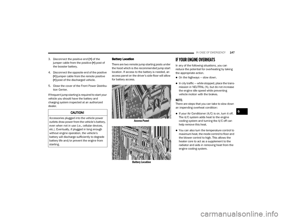
There are two remote jump starting posts under
the hood which is the recommended jump start
location. If access to the battery is needed, an
access panel on the driver’s side floor will allow
for battery access.
Access Panel
Battery Location
IF YOUR ENGINE OVERHEATS
In any of the following situations, you can
reduce the potential for overheating by taking
the appropriate action.
On the highways — slow down.
In city traffic — while stopped, place the trans -
mission in NEUTRAL (N), but do not increase
the engine idle speed while preventing
vehicle motion with the brakes.
NOTE:
There are steps that you can take to slow down
an impending overheat condition:
If your Air Conditioner (A/C) is on, turn it off.
The A/C system adds heat to the engine
cooling system and turning the A/C off can
help remove this heat.
You can also turn the temperature control to
maximum heat, the mode control to floor and
the blower control to high. This allows the
heater core to act as a supplement to the
radiator and aids in removing heat from the
engine cooling system.
CAUTION!
Accessories plugged into the vehicle power
outlets draw power from the vehicle’s battery,
even when not in use (i.e., cellular devices,
etc.). Eventually, if plugged in long enough
without engine operation, the vehicle’s
battery will discharge sufficiently to degrade
battery life and/or prevent the engine from
starting.
6
20_VF_OM_EN_US_t.book Page 147
Page 151 of 264
IN CASE OF EMERGENCY149
FREEING A STUCK VEHICLE
If your vehicle becomes stuck in mud, sand, or
snow, it can often be moved using a rocking
motion. Turn the steering wheel right and left to
clear the area around the front wheels. Shift
back and forth between DRIVE (D) and
REVERSE (R), while gently pressing the acceler -
ator. Use the least amount of accelerator pedal
pressure that will maintain the rocking motion,
without spinning the wheels or racing the
engine. NOTE:
Push the “ESC OFF” switch, to place the Elec
-
tronic Stability Control (ESC) system in “Partial
OFF” mode, before rocking the vehicle. Refer to
“Electronic Brake Control System” in “Safety”
for further information. Once the vehicle has
been freed, push the “ESC OFF” switch again to
restore “ESC ON” mode.
TOWING A DISABLED VEHICLE
This section describes procedures for towing a
disabled vehicle using a commercial towing
service.
CAUTION!
Racing the engine or spinning the wheels may
lead to transmission overheating and failure.
Allow the engine to idle with the transmission
in NEUTRAL for at least one minute after
every five rocking-motion cycles. This will
minimize overheating and reduce the risk of
transmission failure during prolonged efforts
to free a stuck vehicle.
WARNING!
Fast spinning tires can be dangerous. Forces
generated by excessive wheel speeds may
cause damage, or even failure, of the axle
and tires. A tire could explode and injure
someone. Do not spin your vehicle's wheels
faster than 30 mph (48 km/h) or for longer than 30 seconds continuously without
stopping when you are stuck and do not let
anyone near a spinning wheel, no matter
what the speed.
CAUTION!
When “rocking” a stuck vehicle by shifting
between DRIVE and REVERSE, do not spin
the wheels faster than 15 mph (24 km/h), or drivetrain damage may result.
Spinning the wheels too fast may lead to
transmission overheating and failure. It can
also damage the tires. Do not spin the
wheels above 30 mph (48 km/h) while in
gear (no transmission shifting occurring).
6
20_VF_OM_EN_US_t.book Page 149
Page 152 of 264
150IN CASE OF EMERGENCY
Proper towing or lifting equipment is required to
prevent damage to your vehicle. Use only tow
bars and other equipment designed for this
purpose, following equipment manufacturer’s
instructions. Use of safety chains is mandatory.
Attach a tow bar or other towing device to main
structural members of the vehicle, not to
bumpers or associated brackets. State and
local laws regarding vehicles under tow must be
observed.
If you must use the accessories (wipers,
defrosters, etc.) while being towed, the ignition
must be in the ON/RUN mode. If the key fob is unavailable or the vehicle's
battery is discharged, refer to “Gear Selector
Override” in this section for instructions on
shifting the automatic transmission out of PARK
(P) for towing.Automatic Transmission
The manufacturer recommends towing your
vehicle with all four wheels
OFF the ground
using a flatbed.
If flatbed equipment is not available, and the
transmission is operable, this vehicle may be
towed (with front wheels on the ground) under
the following conditions:
The transmission must be in NEUTRAL (N).
The towing speed must not exceed 25 mph
(40 km/h).
The towing distance must not exceed
15 miles (24 km).
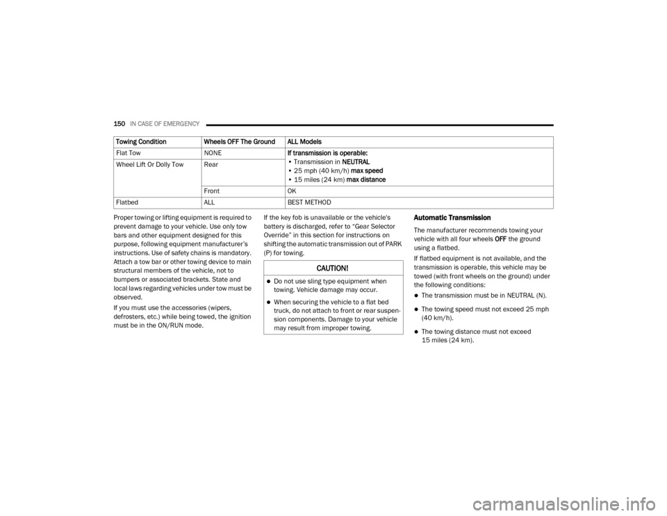
Towing Condition
Wheels OFF The Ground ALL Models
Flat Tow NONEIf transmission is operable:
• Transmission in NEUTRAL
• 25 mph (40 km/h) max speed
• 15 miles (24 km) max distance
Wheel Lift Or Dolly Tow Rear
FrontOK
Flatbed ALLBEST METHOD
CAUTION!
Do not use sling type equipment when
towing. Vehicle damage may occur.
When securing the vehicle to a flat bed
truck, do not attach to front or rear suspen -
sion components. Damage to your vehicle
may result from improper towing.
20_VF_OM_EN_US_t.book Page 150
Page 162 of 264
160SERVICING AND MAINTENANCE
Engine Air Cleaner Filter Selection
The quality of replacement engine air cleaner
filters varies considerably. Only high quality
filters should be used to ensure most efficient
service. Mopar engine air cleaner filters are a
high quality filter and are recommended.
Air Conditioner Maintenance
For best possible performance, your air condi -
tioner should be checked and serviced by an
authorized dealer at the start of each warm
season. This service should include cleaning of
the condenser fins and a performance test.
Drive belt tension should also be checked at
this time.
Refrigerant Recovery And Recycling
R-134a Air Conditioning Refrigerant is a hydro -
fluorocarbon (HFC) that is an ozone-saving
product. However, the manufacturer recom -
mends that air conditioning service be
performed by authorized dealer or other service
facilities using recovery and recycling equip -
ment.
NOTE:
Use only manufacturer approved A/C system
PAG compressor oil and refrigerants.
Cabin Air Filter (A/C Air Filter)
Refer to the “Maintenance Plan” for the proper
maintenance intervals.
WARNING!
The air induction system (air cleaner, hoses,
etc.) can provide a measure of protection in
the case of engine backfire. Do not remove
the air induction system (air cleaner, hoses,
etc.) unless such removal is necessary for
repair or maintenance. Make sure that no
one is near the engine compartment before
starting the vehicle with the air induction
system (air cleaner, hoses, etc.) removed.
Failure to do so can result in serious personal
injury.
WARNING!
Use only refrigerants and compressor lubri -
cants approved by the manufacturer for
your air conditioning system. Some unap -
proved refrigerants are flammable and can
explode, injuring you. Other unapproved
refrigerants or lubricants can cause the
system to fail, requiring costly repairs.
Refer to Warranty Information Book, for
further warranty information.
The air conditioning system contains refrig -
erant under high pressure. To avoid risk of
personal injury or damage to the system,
adding refrigerant or any repair requiring
lines to be disconnected should be done by
an experienced technician.
CAUTION!
Do not use chemical flushes in your air
conditioning system as the chemicals can
damage your air conditioning components.
Such damage is not covered by the New
Vehicle Limited Warranty.
WARNING!
Do not remove the cabin air filter while the
vehicle is running, or while the ignition is in
the ACC or ON/RUN mode. With the cabin air
filter removed and the blower operating, the
blower can contact hands and may propel dirt
and debris into your eyes, resulting in
personal injury.
20_VF_OM_EN_US_t.book Page 160
Page 180 of 264
178SERVICING AND MAINTENANCE
Radial Ply Tires
Tire Repair
If your tire becomes damaged, it may be
repaired if it meets the following criteria:
The tire has not been driven on when flat.
The damage is only on the tread section of
your tire (sidewall damage is not repairable).
The puncture is no greater than a ¼ of an
inch (6 mm).
Consult an authorized tire dealer for tire repairs
and additional information. Damaged Run Flat tires, or Run Flat tires that
have experienced a loss of pressure should be
replaced immediately with another Run Flat tire
of identical size and service description (Load
Index and Speed Symbol). Replace the tire pres
-
sure sensor as well as it is not designed to be
reused.
Run Flat Tires — If Equipped
Run Flat tires allow you the capability to drive
50 miles (80 km) at 50 mph (80 km/h) after a
rapid loss of inflation pressure. This rapid loss
of inflation is referred to as the Run Flat mode.
A Run Flat mode occurs when the tire inflation
pressure is of/or below 14 psi (96 kPa). Once a
Run Flat tire reaches the run flat mode it has
limited driving capabilities and needs to be
replaced immediately. A Run Flat tire is not
repairable. When a run flat tire is changed after
driving with underinflated tire condition, please
replace the TPM sensor as it is not designed to
be reused when driven under run flat mode 14
psi (96 kPa) condition.
NOTE:
TPM Sensor must be replaced after driving the
vehicle on a flat tire condition. It is not recommended driving a vehicle loaded
at full capacity or to tow a trailer while a tire is in
the run flat mode.
See the tire pressure monitoring section for
more information.
Tire Spinning
When stuck in mud, sand, snow, or ice condi
-
tions, do not spin your vehicle's wheels
above 30 mph (48 km/h) or for longer than
30 seconds continuously without stopping.
Refer to “Freeing A Stuck Vehicle” in “In Case Of
Emergency” for further information.
WARNING!
Combining radial ply tires with other types of
tires on your vehicle will cause your vehicle to
handle poorly. The instability could cause a
collision. Always use radial ply tires in sets of
four. Never combine them with other types of
tires.
WARNING!
Fast spinning tires can be dangerous.
Forces generated by excessive wheel
speeds may cause tire damage or failure. A
tire could explode and injure someone. Do
not spin your vehicle's wheels faster than
30 mph (48 km/h) for more than 30
seconds continuously when you are stuck,
and do not let anyone near a spinning
wheel, no matter what the speed.
20_VF_OM_EN_US_t.book Page 178
Page 195 of 264
TECHNICAL SPECIFICATIONS193
Materials Added To Fuel
Besides using unleaded gasoline with the
proper octane rating, gasolines that contain
detergents, corrosion and stability additives are
recommended. Using gasolines that have these
additives will help improve fuel economy,
reduce emissions, and maintain vehicle perfor -
mance.
Designated TOP TIER Detergent Gaso -
line contains a higher level of deter -
gents to further aide in minimizing
engine and fuel system deposits.
When available, the usage of TOP TIER Deter -
gent gasoline is recommended. Visit
www.toptiergas.com for a list of TOP TIER Deter -
gent Gasoline Retailers.
Indiscriminate use of fuel system cleaning
agents should be avoided. Many of these mate -
rials intended for gum and varnish removal may
contain active solvents or similar ingredients.
These can harm fuel system gasket and
diaphragm materials.
Gasoline/Oxygenate Blends
Some fuel suppliers blend unleaded gasoline
with oxygenates such as ethanol. Problems that result from using gasoline
containing more than 15% ethanol (E-15) or
gasoline containing methanol are not the
responsibility of the manufacturer and may void
or not be covered under New Vehicle Limited
Warranty.
Do Not Use E-85 In Non-Flex Fuel Vehicles
Non-Flex Fuel Vehicles (FFV) are compatible
with gasoline containing up to 15% ethanol
(E-15). Use of gasoline with higher ethanol
content may void the New Vehicle Limited
Warranty.If a Non-FFV vehicle is inadvertently fueled with
E-85 fuel, the engine will have some or all of
these symptoms:
Operate in a lean mode.
OBD II Malfunction Indicator Light on.
Poor engine performance.
Poor cold start and cold drivability.
Increased risk for fuel system component
corrosion.
CNG And LP Fuel System Modifications
Modifications that allow the engine to run on
Compressed Natural Gas (CNG) or Liquid
Propane (LP) may result in damage to the
engine, emissions, and fuel system compo
-
nents. Problems that result from running CNG
or LP are not the responsibility of the manufac -
turer and may void or not be covered under the
New Vehicle Limited Warranty.
CAUTION!
DO NOT use E-85, gasoline containing
methanol, or gasoline containing more than
15% ethanol (E-15). Use of these blends may
result in starting and drivability problems,
damage critical fuel system components,
cause emissions to exceed the applicable
standard, and/or cause the Malfunction
Indicator Light to illuminate. Please observe
pump labels as they should clearly
communicate if a fuel contains greater than
15% ethanol (E-15).
8
20_VF_OM_EN_US_t.book Page 193