remote start Ram ProMaster 2020 Owner's Manual
[x] Cancel search | Manufacturer: RAM, Model Year: 2020, Model line: ProMaster, Model: Ram ProMaster 2020Pages: 264, PDF Size: 10.11 MB
Page 11 of 264
9
GETTING TO KNOW YOUR VEHICLE
KEYS
Key Fob
Your vehicle uses a key start ignition system.
The ignition system consists of a key fob with a
Remote Keyless Entry (RKE) and an ignition
switch.
The key fob contains an integrated mechanical
key. To use the mechanical key, simply push the
mechanical key release button.
The vehicle is supplied with a code card
containing key code numbers to order duplicate
keys, and the authorized dealer that sold you
your new vehicle has the key code numbers for
your vehicle locks. These numbers can be used
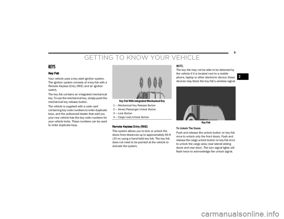
to order duplicate keys.Key Fob With Integrated Mechanical Key
Remote Keyless Entry (RKE)
This system allows you to lock or unlock the
doors from distances up to approximately 66 ft
(20 m) using a hand-held key fob. The key fob
does not need to be pointed at the vehicle to
activate the system. NOTE:
The key fob may not be able to be detected by
the vehicle if it is located next to a mobile
phone, laptop or other electronic device; these
devices may block the key fob’s wireless signal.
Key Fob
To Unlock The Doors
Push and release the unlock button on key fob
once to unlock only the front doors. Push and
release the cargo unlock button on key fob once
to unlock the cargo area (rear lateral sliding
doors and rear door). The turn signal lights will
flash twice to acknowledge the unlock signal.
1 — Mechanical Key Release Button
2 — Driver/Passenger Unlock Button
3 — Lock Button
4 — Cargo Lock/Unlock Button
2
20_VF_OM_EN_US_t.book Page 9
Page 14 of 264
12GETTING TO KNOW YOUR VEHICLE
Key-In-Ignition Reminder
Opening the driver's door when the key is in the
ignition and the ignition switch position is STOP
(OFF/LOCK) sounds a signal to remove the key.
SENTRY KEY
The Sentry Key Immobilizer System prevents
unauthorized vehicle operation by disabling the
engine. The system does not need to be armed
or activated. Operation is automatic, regardless
of whether the vehicle is locked or unlocked.
The system uses ignition keys which have an
embedded electronic chip (transponder) to
prevent unauthorized vehicle operation. There -
fore, only keys that are programmed to the
vehicle can be used to start and operate the
vehicle. NOTE:
A key which has not been programmed is also
considered an invalid key, even if it is cut to fit
the ignition switch lock cylinder for that vehicle.
If the vehicle security light is on after the key is
turned to the MAR (ACC/ON/RUN) position, it
indicates that there is a problem with the elec
-
tronics.
All of the keys provided with your new vehicle
have been programmed to the vehicle elec -
tronics.
Replacement Keys
NOTE:
Only keys that have been programmed to the
vehicle electronics can be used to start the
vehicle. Once a Sentry Key has been
programmed to a vehicle, it cannot be
programmed to any other vehicle. When having
the Sentry Key Immobilizer System serviced,
bring all vehicle keys with you to an authorized
dealer.
The VIN is required for authorized dealer
replacement of keys. Duplication of keys may
be performed at an authorized dealer.
General Information
The following regulatory statement applies to all
Radio Frequency (RF) devices equipped in this
vehicle:
CAUTION!
An unlocked vehicle is an invitation. Always
remove the key from the ignition and lock all
the doors when leaving the vehicle
unattended.
CAUTION!
Always remove the Sentry Key from the
vehicle and lock all doors when leaving the
vehicle unattended.
The Sentry Key Immobilizer system is not
compatible with some aftermarket remote
starting systems. Use of these systems may
result in vehicle starting problems and loss
of security protection.
20_VF_OM_EN_US_t.book Page 12
Page 147 of 264
IN CASE OF EMERGENCY145
JUMP STARTING
If your vehicle has a discharged battery, it can
be jump started using a set of jumper cables
and a battery in another vehicle or by using a
portable battery booster pack. Jump starting
can be dangerous if done improperly, so please
follow the procedures in this section carefully.
NOTE:
When using a portable battery booster pack,
follow the manufacturer’s operating instruc -
tions and precautions.
Preparations For Jump Start
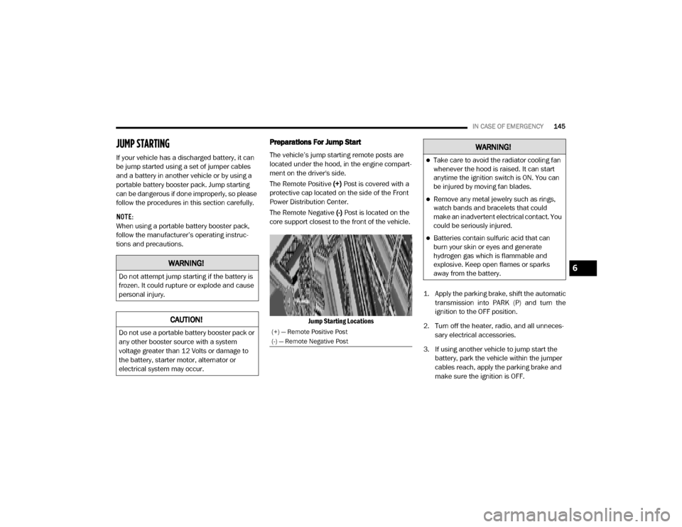
The vehicle’s jump starting remote posts are
located under the hood, in the engine compart -
ment on the driver's side.
The Remote Positive (+) Post is covered with a
protective cap located on the side of the Front
Power Distribution Center.
The Remote Negative (-) Post is located on the
core support closest to the front of the vehicle.
Jump Starting Locations 1. Apply the parking brake, shift the automatic
transmission into PARK (P) and turn the
ignition to the OFF position.
2. Turn off the heater, radio, and all unneces -
sary electrical accessories.
3. If using another vehicle to jump start the battery, park the vehicle within the jumper
cables reach, apply the parking brake and
make sure the ignition is OFF.
WARNING!
Do not attempt jump starting if the battery is
frozen. It could rupture or explode and cause
personal injury.
CAUTION!
Do not use a portable battery booster pack or
any other booster source with a system
voltage greater than 12 Volts or damage to
the battery, starter motor, alternator or
electrical system may occur.(+) — Remote Positive Post
(-) — Remote Negative Post
WARNING!
Take care to avoid the radiator cooling fan
whenever the hood is raised. It can start
anytime the ignition switch is ON. You can
be injured by moving fan blades.
Remove any metal jewelry such as rings,
watch bands and bracelets that could
make an inadvertent electrical contact. You
could be seriously injured.
Batteries contain sulfuric acid that can
burn your skin or eyes and generate
hydrogen gas which is flammable and
explosive. Keep open flames or sparks
away from the battery.
6
20_VF_OM_EN_US_t.book Page 145
Page 148 of 264
146IN CASE OF EMERGENCY
Jump Starting Procedure
Connecting The Jumper Cables
1. Connect the positive (+) end of the jumper
cable to the remote positive (+) post of the
discharged vehicle.
NOTE:
The remote positive (+) post is located in the
engine compartment on the driver's side under
the cover of the Front Power Distribution
Center.
2. Connect the opposite end of the positive (+)
jumper cable to the positive (+) post of the
booster battery.
3. Connect the negative end (-) of the jumper
cable to the negative (-) post of the booster
battery.
4. Connect the opposite end of the negative (-)
jumper cable to the remote negative (-) post
of the discharged vehicle.
NOTE:
The remote negative (-) post is located in the
front of the engine compartment on the driver's
side. 5. Start the engine in the vehicle that has the
booster battery. Let the engine idle a few
minutes and then start the engine in the
vehicle with the discharged battery.
6. Once the engine is started, disconnect the jumper cables in the reverse sequence.
Disconnecting The Jumper Cables
1. Disconnect the negative end (-) of the
jumper cable from the remote negative (-)
post of the vehicle with the discharged
battery.
2. Disconnect the opposite end of the negative (-) jumper cable from the negative (-) post of
the booster battery.WARNING!
Do not allow vehicles to touch each other as
this could establish a ground connection and
personal injury could result.
WARNING!
Failure to follow this jump starting procedure
could result in personal injury or property
damage due to battery explosion.
CAUTION!
Failure to follow these procedures could
result in damage to the charging system of
the booster vehicle or the discharged vehicle.
WARNING!
Do not connect the jumper cable to the
negative (-) post of the discharged battery.
The resulting electrical spark could cause the
battery to explode and could result in
personal injury. Only use the specific ground
point, do not use any other exposed metal
parts.
20_VF_OM_EN_US_t.book Page 146
Page 149 of 264
IN CASE OF EMERGENCY147
3. Disconnect the positive end (+) of the
jumper cable from the positive (+) post of
the booster battery.
4. Disconnect the opposite end of the positive (+) jumper cable from the remote positive
(+) post of the discharged vehicle.
5. Close the cover of the Front Power Distribu -
tion Center.
If frequent jump starting is required to start your
vehicle you should have the battery and
charging system inspected at an authorized
dealer.Battery Location
There are two remote jump starting posts under
the hood which is the recommended jump start
location. If access to the battery is needed, an
access panel on the driver’s side floor will allow
for battery access.
Access Panel
Battery Location
IF YOUR ENGINE OVERHEATS
In any of the following situations, you can
reduce the potential for overheating by taking
the appropriate action.
On the highways — slow down.
In city traffic — while stopped, place the trans -
mission in NEUTRAL (N), but do not increase
the engine idle speed while preventing
vehicle motion with the brakes.
NOTE:
There are steps that you can take to slow down
an impending overheat condition:
If your Air Conditioner (A/C) is on, turn it off.
The A/C system adds heat to the engine
cooling system and turning the A/C off can
help remove this heat.
You can also turn the temperature control to
maximum heat, the mode control to floor and
the blower control to high. This allows the
heater core to act as a supplement to the
radiator and aids in removing heat from the
engine cooling system.
CAUTION!
Accessories plugged into the vehicle power
outlets draw power from the vehicle’s battery,
even when not in use (i.e., cellular devices,
etc.). Eventually, if plugged in long enough
without engine operation, the vehicle’s
battery will discharge sufficiently to degrade
battery life and/or prevent the engine from
starting.
6
20_VF_OM_EN_US_t.book Page 147
Page 253 of 264

251
Cargo Area Cover
..................................... 37
Cargo Compartment
.................................. 37
Cargo Light
............................................ 26
Certification Label
.................................. 112
Change Oil Indicator
.................................. 44
Changing A Flat Tire
........................ 133, 168
Chart, Tire Sizing
.................................... 169
Check Engine Light
(Malfunction Indicator Light)
......................... 55
Checking Your Vehicle For Safety
................... 89
Checks, Safety
........................................ 89
Child Restraint
........................................ 83
Child Restraints
Booster Seats.................................... 86Child Seat Installation.......................... 88Infant And Child Restraints................... 85Older Children And Child Restraints........ 85
Clean Air Gasoline
.................................. 192
Cleaning
Wheels........................................... 183
Climate Control
........................................ 28Manual............................................ 28Rear................................................ 32
Cold Weather Operation
.............................. 92
Compact Spare Tire
................................. 181
Contract, Service
.................................... 247
Cooling Pressure Cap (Radiator Cap)
............. 165
Cooling System
...................................... 163Adding Coolant (Antifreeze)................. 164Coolant Level........................... 163, 165Cooling Capacity............................... 195Disposal Of Used Coolant................... 165Drain, Flush, And Refill....................... 163Inspection....................................... 165Points To Remember......................... 165Pressure Cap................................... 165Radiator Cap................................... 165Selection Of Coolant (Antifreeze).. 164, 195
Corrosion Protection
................................ 187
Cruise Light
............................................53
Cupholders
..................................... 38, 190
Customer Assistance
............................... 246
Customer Programmable Features
................ 199
Cybersecurity
........................................ 198
D
Dealer Service
....................................... 158
Defroster, Windshield
.................................90
Diagnostic System, Onboard
......................... 54
Dimmer Control Switch
............................... 27
Dimmer Switch
Headlight..........................................24
Dipsticks
Automatic Transmission..................... 168Power Steering................................. 103
Disable Vehicle Towing
............................. 149
Disposal
Antifreeze (Engine Coolant)................ 165
Door Ajar
.............................................. 47
Door Ajar Light
........................................ 47
Door Locks
............................................ 14Automatic........................................ 15
Doors
.................................................. 14
Driver’s Seat Back Tilt
............................... 15
Driving
Through Flowing, Rising, Or Shallow
Standing Water
............................... 121
E
Electric Brake Control System
....................... 57
Electric Remote Mirrors
.............................. 22
Electrical Power Outlets
............................. 39
Electronic Speed Control (Cruise Control)
....... 103
Electronic Stability Control (ESC)
................... 57
Electronic Throttle Control Warning Light
.......... 48
Emergency, In Case Of
Freeing Vehicle When Stuck............... 149Jacking...................................133, 168Jump Starting.................................. 145
Emission Control System Maintenance
............ 55
11
20_VF_OM_EN_US_t.book Page 251
Page 255 of 264

253
H
Hazard
Driving Through Flowing, Rising,
Or Shallow Standing Water
................. 121
Hazard Warning Flashers
.......................... 123
Head Restraints
....................................... 20
Headlights
Cleaning......................................... 187High Beam........................................ 24High Beam/Low Beam Select Switch....... 24Passing............................................ 24Switch.............................................. 23
Heated Mirrors
........................................ 23
Heated Seats
.......................................... 18
Heater, Engine Block
................................. 93
High Beam/Low Beam Select (Dimmer) Switch
... 24
Hill Start Assist
........................................ 60
Hitches
Trailer Towing.................................. 114
Hood Prop
............................................. 36
Hood Release
......................................... 36
I
Ignition
.................................................11Key.............................................. 9, 11Switch.............................................. 11
Ignition Key Removal
.................................11
Illuminated Entry
......................................27
Immobilizer (Sentry Key)
............................. 12
Inside Rearview Mirror
................................21
Instrument Cluster
.............................. 41, 53Display............................................. 43
Instrument Panel Lens Cleaning
................... 189
Interior And Instrument Lights
.......................25
Interior Appearance Care
........................... 188
Interior Lights
..........................................25
Intermittent Wipers (Delay Wipers)
..................28
Introduction
..............................................7
iPod/USB/MP3 Control
............................. 238
J
Jack Location
........................................ 133
Jack Operation
.............................. 133, 168
Jacking And Tire Changing
......................... 133
Jacking And Tire Changing Instructions
...........135
Jump Starting
........................................ 145
K
Key Fob
Programming Additional Key Fobs
.......... 10
Key Fob Battery Service (Remote Keyless Entry)
.. 10
Key Fob Programming (Remote Keyless Entry)
.... 10
Key-In Reminder
...................................... 12
Keys
..................................................... 9Replacement.................................... 12Sentry (Immobilizer)............................ 12
L
Lane Change Assist
.................................. 25
Lap/Shoulder Belts
.................................. 67
Latches
................................................ 91Hood............................................... 36
Lead Free Gasoline
................................ 192
Leaks, Fluid
........................................... 91
Life Of Tires
......................................... 179
Light Bulbs
.....................................91, 123
Lights
.................................................. 91Air Bag................................. 47, 73, 90Brake Assist Warning.......................... 59Brake Warning.................................. 48Bulb Replacement............................ 123Cruise............................................. 53Daytime Running............................... 24Dimmer Switch, Headlight...............23, 2411
20_VF_OM_EN_US_t.book Page 253