steering Ram ProMaster 2020 Owner's Guide
[x] Cancel search | Manufacturer: RAM, Model Year: 2020, Model line: ProMaster, Model: Ram ProMaster 2020Pages: 264, PDF Size: 10.11 MB
Page 78 of 264
76SAFETY
Because air bag sensors measure vehicle
deceleration over time, vehicle speed and
damage by themselves are not good indicators
of whether or not an air bag should have
deployed.
Seat belts are necessary for your protection in
all collisions, and also are needed to help keep
you in position, away from an inflating air bag.
When the ORC detects a collision requiring the
front air bags, it signals the inflator units. A large
quantity of non-toxic gas is generated to inflate
the front air bags.
The steering wheel hub trim cover and the
upper passenger side of the instrument panel
separate and fold out of the way as the air bags
inflate to their full size. The front air bags fully
inflate in less time than it takes to blink your
eyes. The front air bags then quickly deflate
while helping to restrain the driver and front
passenger.Supplemental Side Air Bags
Supplemental Seat-Mounted Side Air Bags
(SABs)
This vehicle is equipped with Supplemental
Seat-Mounted Side Air Bags (SABs).
Supplemental Seat-Mounted Side Air Bags
(SABs) are located in the outboard side of the
front seats. The SABs are marked with “SRS
AIRBAG” or “AIRBAG” on a label or on the seat
trim on the outboard side of the seats.
The SABs may help to reduce the risk of occu -
pant injury during certain side impacts, in addi -
tion to the injury reduction potential provided by
the seat belts and body structure.
Front Supplemental Seat-Mounted Side Air Bag Label
When the SAB deploys, it opens the seam on
the outboard side of the seatback’s trim cover.
The inflating SAB deploys through the seat
seam into the space between the occupant and
the door. The SAB moves at a very high speed
and with such a high force that it could injure
occupants if they are not seated properly, or if
items are positioned in the area where the SAB
inflates. Children are at an even greater risk of
injury from a deploying air bag.
WARNING!
Do not use accessory seat covers or place
objects between you and the Side Air Bags;
the performance could be adversely affected
and/or objects could be pushed into you,
causing serious injury.
20_VF_OM_EN_US_t.book Page 76
Page 81 of 264

SAFETY79
NOTE:
Air bag covers may not be obvious in the inte -
rior trim, but they will open during air bag
deployment. Rollover Events
Side Air Bags and seat belt pretensioners are
designed to activate in certain rollover events.
The Occupant Restraint Controller (ORC) deter
-
mines whether deployment in a particular roll-
over event is appropriate, based on the severity
and type of collision. Vehicle damage by itself is
not a good indicator of whether or not Side Air
Bags and seat belt pretensioners should have
deployed.
The Side Air Bags and seat belt pretensioners
will not deploy in all rollover events. The rollover
sensing system determines if a rollover event
may be in progress and whether deployment is
appropriate. In the event the vehicle experi -
ences a rollover or near rollover event, and
deployment is appropriate, the rollover sensing
system will deploy the side air bags and seat
belt pretensioners on both sides of the vehicle.
The SABICs may help reduce the risk of partial
or complete ejection of vehicle occupants
through side windows in certain rollover or side
impact events.
Air Bag System Components
NOTE:
The Occupant Restraint Controller (ORC) moni -
tors the internal circuits and interconnecting
wiring associated with electrical Air Bag System
Components listed below:
Occupant Restraint Controller (ORC)
Air Bag Warning Light
Steering Wheel and Column
Instrument Panel
Driver and Front Passenger Air Bags
Seat Belt Buckle Switch
Supplemental Side Air Bags
Front and Side Impact Sensors
Seat Belt Pretensioners
WARNING!
Side Air Bags need room to inflate. Do not
lean against the door or window. Sit upright
in the center of the seat.
Being too close to the Side Air Bags during
deployment could cause you to be severely
injured or killed.
Relying on the Side Air Bags alone could
lead to more severe injuries in a collision.
The Side Air Bags work with your seat belt
to restrain you properly. In some collisions,
Side Air Bags won’t deploy at all. Always
wear your seat belt even though you have
Side Air Bags.4
20_VF_OM_EN_US_t.book Page 79
Page 83 of 264
SAFETY81
(Continued)
NOTE:
After an accident, remember to cycle the igni -
tion to the STOP (OFF/LOCK) position and
remove the key from the ignition switch to avoid
draining the battery. Carefully check the vehicle
for fuel leaks in the engine compartment and on
the ground near the engine compartment and
fuel tank before resetting the system and
starting the engine. If there are no fuel leaks or
damage to the vehicle electrical devices (e.g.
headlights) after an accident, reset the Fuel Cut
Off Switch by following the procedure described
below. If you have any doubt, contact an autho -
rized dealer.
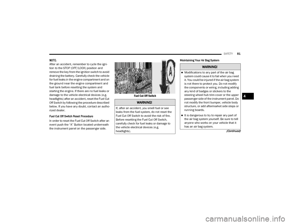
Fuel Cut Off Switch Reset Procedure
In order to reset the Fuel Cut Off Switch after an
event push the “A” Button located underneath
the instrument panel on the passenger side. Fuel Cut Off Switch
Maintaining Your Air Bag System
WARNING!
If, after an accident, you smell fuel or see
leaks from the fuel system, do not reset the
Fuel Cut Off Switch to avoid the risk of fire.
Before resetting the Fuel Cut Off Switch,
carefully check for fuel leaks or damage to
the vehicle electrical devices (e.g.
headlights).
WARNING!
Modifications to any part of the air bag
system could cause it to fail when you need
it. You could be injured if the air bag system
is not there to protect you. Do not modify
the components or wiring, including adding
any kind of badges or stickers to the
steering wheel hub trim cover or the upper
passenger side of the instrument panel. Do
not modify the front bumper, vehicle body
structure, or add aftermarket side steps or
running boards.
It is dangerous to try to repair any part of
the air bag system yourself. Be sure to tell
anyone who works on your vehicle that it
has an air bag system.
4
20_VF_OM_EN_US_t.book Page 81
Page 104 of 264

102STARTING AND OPERATING
Torque Converter Clutch
A feature designed to improve fuel economy
has been included in the automatic transmis -
sion on your vehicle. A clutch within the torque
converter engages automatically at calibrated
speeds. This may result in a slightly different
feeling or response during normal operation in
the upper gears. When the vehicle speed drops
or during some accelerations, the clutch auto -
matically disengages.
NOTE:
The torque converter clutch will not engage
until the transmission fluid and engine
coolant are warm [usually after 1 to 3 miles
(2 to 5 km) of driving]. Because the engine
speed is higher when the torque converter
clutch is not engaged, it may seem as if the
transmission is not shifting into Overdrive
when cold. This is normal. Using the Elec -
tronic Range Select (ERS) shift control, when
the transmission is sufficiently warm, will
demonstrate that the transmission is able to
shift into and out of Overdrive.
If the vehicle has not been driven for several
days, the first few seconds of operation after
shifting the transmission into gear may seem
sluggish. This is due to the fluid partially
draining from the torque converter into the
transmission. This condition is normal and
will not cause damage to the transmission.
The torque converter will refill within five
seconds after starting the engine.
POWER STEERING
The standard power steering system will give
you good vehicle response and increased ease
of maneuverability in tight spaces. The system
will provide mechanical steering capability if
power assist is lost.
If for some reason the power assist is inter -
rupted, it will still be possible to steer your
vehicle. Under these conditions, you will
observe a substantial increase in steering
effort, especially at very low vehicle speeds and
during parking maneuvers. NOTE:
Increased noise levels at the end of the
steering wheel travel are considered normal
and do not indicate that there is a problem
with the power steering system.
Upon initial start-up in cold weather, the
power steering pump may make noise for a
short amount of time. This is due to the cold,
thick fluid in the steering system. This noise
should be considered normal, and it does not
in any way damage the steering system.
CAUTION!
Prolonged operation of the steering system at
the end of the steering wheel travel will
increase the steering fluid temperature and it
should be avoided when possible. Damage to
the power steering pump may occur.
20_VF_OM_EN_US_t.book Page 102
Page 105 of 264
STARTING AND OPERATING103
Power Steering Fluid Check
Checking the power steering fluid level at a
defined service interval is not required. The fluid
should be checked at every oil change if a leak
is suspected, abnormal noises are apparent,
and/or the system is not functioning as antici -
pated. Coordinate inspection efforts through an
authorized dealer. If necessary, add fluid to restore to the proper
indicated level. With a clean cloth, wipe any
spilled fluid from all surfaces. Refer to “Fluids
And Lubricants” in “Technical Specifications”
for further information.
SPEED CONTROL — IF EQUIPPED
When engaged, the Speed Control takes over
accelerator operations at speeds greater than
25 mph (40 km/h) up to the maximum speed of
100 mph (160 km/h).
The Speed Control lever is located on the left
side of the steering column.
Speed Control Lever NOTE:
In order to ensure proper operation, the Speed
Control system has been designed to shut down
if multiple Speed Control functions are operated
at the same time. If this occurs, the Speed
Control system can be reactivated by rotating
the Speed Control ON/OFF center ring and
resetting the desired vehicle set speed.
To Activate
Rotate the center ring upward on the Speed
Control lever to turn the system on. The Cruise
Indicator Light in the instrument cluster display
will illuminate. To turn the system off, rotate the
center ring upward a second time. The Cruise
Indicator Light will turn off. The system should
be turned off when not in use.WARNING!
Fluid level should be checked on a level
surface and with the engine off to prevent
injury from moving parts and to ensure
accurate fluid level reading. Do not overfill.
Use only manufacturer's recommended
power steering fluid.
CAUTION!
Do not use chemical flushes in your power
steering system as the chemicals can
damage your power steering components.
Such damage is not covered by the New
Vehicle Limited Warranty.
WARNING!
Leaving the Speed Control system on when
not in use is dangerous. You could
accidentally set the system or cause it to go
faster than you want. You could lose control
and have an accident. Always leave the
system off when you are not using it.
5
20_VF_OM_EN_US_t.book Page 103
Page 116 of 264
114STARTING AND OPERATING
Tongue Weight (TW)
The Tongue Weight (TW) is the downward force
exerted on the hitch ball by the trailer. You must
consider this as part of the load on your vehicle.
Trailer Frontal Area
The frontal area is the maximum height multi -
plied by the maximum width of the front of a
trailer.
Trailer Sway Control
The Trailer Sway Control (TSC) can be a
mechanical telescoping link that can be
installed between the hitch receiver and the
trailer tongue that typically provides adjustable
friction associated with the telescoping motion
to dampen any unwanted trailer swaying
motions while traveling. If equipped, the electronic TSC recognizes a
swaying trailer and automatically applies indi
-
vidual wheel brakes and/or reduces engine
power to attempt to eliminate the trailer sway.
Weight-Carrying Hitch
A weight-carrying hitch supports the trailer
tongue weight, just as if it were luggage located
at a hitch ball or some other connecting point of
the vehicle. These kinds of hitches are the most
popular on the market today and they are
commonly used to tow small and medium sized
trailers.
Weight-Distributing Hitch
A weight-distributing system works by applying
leverage through spring (load) bars. They are
typically used for heavier loads to distribute
trailer tongue weight to the tow vehicle's front
axle and the trailer axle(s). When used in accor -
dance with the manufacturer's directions, it
provides for a more level ride, offering more
consistent steering and brake control thereby
enhancing towing safety. The addition of a fric -
tion/hydraulic sway control also dampens sway
caused by traffic and crosswinds and contrib -
utes positively to tow vehicle and trailer
stability. Trailer sway control and a weight distributing (load equalizing) hitch are recom
-
mended for heavier Tongue Weights (TW) and
may be required depending on vehicle and
trailer configuration/loading to comply with
Gross Axle Weight Rating (GAWR) requirements.
Trailer Hitch Classification
The following chart provides the industry stan -
dard for the maximum trailer weight a given
trailer hitch class can tow and should be used to
assist you in selecting the correct trailer hitch
for your intended towing condition.
WARNING!
It is important that you do not exceed the
maximum front or rear GAWR. A dangerous
driving condition can result if either rating is
exceeded. You could lose control of the
vehicle and have a collision.
WARNING!
An improperly adjusted Weight Distributing
Hitch system may reduce handling,
stability, braking performance, and could
result in a collision.
Weight Distributing Systems may not be
compatible with Surge Brake Couplers.
Consult with your hitch and trailer manufac -
turer or a reputable Recreational Vehicle
dealer for additional information.
20_VF_OM_EN_US_t.book Page 114
Page 118 of 264
116STARTING AND OPERATING
(Continued)
(Continued)
Consider the following items when computing
the weight on the rear axle of the vehicle:
The tongue weight of the trailer.
The weight of any other type of cargo or
equipment put in or on your vehicle.
The weight of the driver and all passengers.
NOTE:
Remember that everything put into or on the
trailer adds to the load on your vehicle. Also,
additional factory-installed options or
dealer-installed options must be considered as
part of the total load on your vehicle. Refer to
the “Tire And Loading Information” placard for
the maximum combined weight of occupants
and cargo for your vehicle.
Towing Requirements
To promote proper break-in of your new vehicle
drivetrain components, the following guidelines
are recommended. Perform the maintenance listed in the “Sched
-
uled Servicing”. Refer to “Scheduled Servicing”
in “Servicing And Maintenance” for the proper
maintenance intervals. When towing a trailer,
never exceed the GAWR or GCWR ratings.
CAUTION!
Do not tow a trailer at all during the first
500 miles (805 km) the new vehicle is driven. The engine, axle or other parts could
be damaged.
Then, during the first 500 miles (805 km) that a trailer is towed, do not drive over
50 mph (80 km/h) and do not make starts
at full throttle. This helps the engine and
other parts of the vehicle wear in at the
heavier loads.
WARNING!
Make certain that the load is secured in the
trailer and will not shift during travel. When
trailering cargo that is not fully secured,
dynamic load shifts can occur that may be
difficult for the driver to control. You could lose
control of your vehicle and have a collision.
When hauling cargo or towing a trailer, do
not overload your vehicle or trailer. Over -
loading can cause a loss of control, poor
performance or damage to brakes, axle,
engine, transmission, steering, suspension,
chassis structure or tires.
CAUTION!
(Continued)
Safety chains must always be used
between your vehicle and trailer. Always
connect the chains to the hook retainers of
the vehicle hitch. Cross the chains under
the trailer tongue and allow enough slack
for turning corners.
Vehicles with trailers should not be parked
on a grade. When parking, apply the
parking brake on the tow vehicle. Put the
tow vehicle transmission in PARK. For
four-wheel drive vehicles, make sure the
transfer case is not in NEUTRAL. Always,
block or "chock" the trailer wheels.
GCWR must not be exceeded.
Total weight must be distributed between
the tow vehicle and the trailer such that the
following four ratings are not exceeded:
GVWR
GTW
GAWR
Tongue weight rating for the trailer
hitch utilized.
WARNING!
(Continued)
20_VF_OM_EN_US_t.book Page 116
Page 130 of 264
128IN CASE OF EMERGENCY
(Continued)
2. Using a suitable tool, flex the housing to lift
the light pod cover away from the unit.
Dome Lamp Light Pod Cover
3. Remove and replace the bulbs as needed.
Dome Lamp Light Bulbs 4. Close the housing cover making sure it
snaps together properly and connect the
lamp.
5. Install overhead console into place making sure to seat the assembly’s forward end
first and then snapping it flush so that the
tension spring is fully seating in the housing.
FUSESUnderhood Fuses
The Front Power Distribution Center is located
on the driver’s side of the engine compartment.
To access the fuses, remove the cover.
Front Power Distribution Center
The ID number of the electrical component
corresponding to each fuse can be found on the
back of the cover.WARNING!
When replacing a blown fuse, always use
an appropriate replacement fuse with the
same amp rating as the original fuse. Never
replace a fuse with another fuse of higher
amp rating. Never replace a blown fuse with
metal wires or any other material. Do not
place a fuse inside a circuit breaker cavity
or vice versa. Failure to use proper fuses
may result in serious personal injury, fire
and/or property damage.
Before replacing a fuse, make sure that the
ignition is off and that all the other services
are switched off and/or disengaged.
If the replaced fuse blows again, contact an
authorized dealer.
If a general protection fuse for safety
systems (air bag system, braking system),
power unit systems (engine system, trans -
mission system) or steering system blows,
contact an authorized dealer.
WARNING!
(Continued)
20_VF_OM_EN_US_t.book Page 128
Page 151 of 264
IN CASE OF EMERGENCY149
FREEING A STUCK VEHICLE
If your vehicle becomes stuck in mud, sand, or
snow, it can often be moved using a rocking
motion. Turn the steering wheel right and left to
clear the area around the front wheels. Shift
back and forth between DRIVE (D) and
REVERSE (R), while gently pressing the acceler -
ator. Use the least amount of accelerator pedal
pressure that will maintain the rocking motion,
without spinning the wheels or racing the
engine. NOTE:
Push the “ESC OFF” switch, to place the Elec
-
tronic Stability Control (ESC) system in “Partial
OFF” mode, before rocking the vehicle. Refer to
“Electronic Brake Control System” in “Safety”
for further information. Once the vehicle has
been freed, push the “ESC OFF” switch again to
restore “ESC ON” mode.
TOWING A DISABLED VEHICLE
This section describes procedures for towing a
disabled vehicle using a commercial towing
service.
CAUTION!
Racing the engine or spinning the wheels may
lead to transmission overheating and failure.
Allow the engine to idle with the transmission
in NEUTRAL for at least one minute after
every five rocking-motion cycles. This will
minimize overheating and reduce the risk of
transmission failure during prolonged efforts
to free a stuck vehicle.
WARNING!
Fast spinning tires can be dangerous. Forces
generated by excessive wheel speeds may
cause damage, or even failure, of the axle
and tires. A tire could explode and injure
someone. Do not spin your vehicle's wheels
faster than 30 mph (48 km/h) or for longer than 30 seconds continuously without
stopping when you are stuck and do not let
anyone near a spinning wheel, no matter
what the speed.
CAUTION!
When “rocking” a stuck vehicle by shifting
between DRIVE and REVERSE, do not spin
the wheels faster than 15 mph (24 km/h), or drivetrain damage may result.
Spinning the wheels too fast may lead to
transmission overheating and failure. It can
also damage the tires. Do not spin the
wheels above 30 mph (48 km/h) while in
gear (no transmission shifting occurring).
6
20_VF_OM_EN_US_t.book Page 149
Page 154 of 264
152
SERVICING AND MAINTENANCE
SCHEDULED SERVICING
Your vehicle is equipped with an automatic oil
change indicator system. The oil change indi-
cator system will remind you that it is time to
take your vehicle in for scheduled maintenance.
Based on engine operation conditions, the oil
change indicator message will illuminate in the
instrument cluster. This means that service is
required for your vehicle. Operating conditions
such as frequent short-trips, trailer tow, and
extremely hot or cold ambient temperatures will
influence when the “Oil Change Required”
message is displayed. Severe Operating Condi-
tions can cause the change oil message to illu -
minate as early as 3,500 miles (5,600 km)
since last reset. Have the vehicle serviced as
soon as possible, within the next 500 miles
(805 km). An authorized dealer will reset the oil change
indicator message after completing the sched
-
uled oil change. If a scheduled oil change is
performed by someone other than an autho -
rized dealer, the message can be reset by refer -
ring to the steps described under “Instrument
Cluster Display” in “Getting To Know Your
Instrument Panel” for further information.
NOTE:
Under no circumstances should oil change
intervals exceed 10,000 miles (16,000 km),
12 months or 350 hours of engine run time,
whichever comes first. The 350 hours of engine
run or idle time is generally only a concern for
fleet customers.
Severe Duty All Models
Change Engine Oil at 4,000 miles (6,500 km) or
350 hours of engine run time if the vehicle is
operated in a dusty and off road environment or
is operated predominately at idle or only very
low engine RPM. This type of vehicle use is
considered Severe Duty. Once A Month Or Before A Long Trip:Check engine oil level
Check windshield washer fluid level
Check the tire inflation pressures and look
for unusual wear or damage. Rotate at the
first sign of irregular wear, even if it occurs
before the oil indicator system turns on
Check the fluid levels of the coolant reservoir,
brake master cylinder, and power steering
and fill as needed
Check function of all interior and exterior
lights
Maintenance Plan
Required Maintenance Intervals
Refer to the maintenance plan on the following
pages for the required maintenance intervals.
20_VF_OM_EN_US_t.book Page 152