lock Ram ProMaster 2020 Owner's Guide
[x] Cancel search | Manufacturer: RAM, Model Year: 2020, Model line: ProMaster, Model: Ram ProMaster 2020Pages: 264, PDF Size: 10.11 MB
Page 82 of 264
80SAFETY
If A Deployment Occurs
The front air bags are designed to deflate imme -
diately after deployment.
NOTE:
Front and/or side air bags will not deploy in all
collisions. This does not mean something is
wrong with the air bag system.
If you do have a collision which deploys the air
bags, any or all of the following may occur:
The air bag material may sometimes cause
abrasions and/or skin reddening to the occu -
pants as the air bags deploy and unfold. The
abrasions are similar to friction rope burns or
those you might get sliding along a carpet or
gymnasium floor. They are not caused by
contact with chemicals. They are not perma -
nent and normally heal quickly. However, if
you haven’t healed significantly within a few
days, or if you have any blistering, see your
doctor immediately.
As the air bags deflate, you may see some
smoke-like particles. The particles are a
normal by-product of the process that gener -
ates the non-toxic gas used for air bag infla -
tion. These airborne particles may irritate the
skin, eyes, nose, or throat. If you have skin or
eye irritation, rinse the area with cool water.
For nose or throat irritation, move to fresh air.
If the irritation continues, see your doctor. If
these particles settle on your clothing, follow
the garment manufacturer’s instructions for
cleaning.
Do not drive your vehicle after the air bags have
deployed. If you are involved in another collision,
the air bags will not be in place to protect you.
NOTE:
Air bag covers may not be obvious in the inte
-
rior trim, but they will open during air bag
deployment.
After any collision, the vehicle should be
taken to an authorized dealer immediately.
Fuel Cut Off Switch
Your vehicle is equipped with a Fuel Cut Off
switch. In the event of an accident, if the
communication network remains intact, and
the power remains intact, depending on the
nature of the event, the Fuel Cut Off Switch may
perform the following functions:
Cut off fuel to the engine and turn off the
engine.
Flash hazard lights as long as the battery has
power or until the hazard light button is
pressed. The hazard lights can be deacti -
vated by pressing the hazard light button.
Turn on the interior lights, which remain on
as long as the battery has power.
Unlock the power door locks.
WARNING!
Deployed air bags and seat belt
pretensioners cannot protect you in another
collision. Have the air bags, seat belt
pretensioners, and the seat belt retractor
assemblies replaced by an authorized dealer
immediately. Also, have the Occupant
Restraint Controller System serviced as well.
20_VF_OM_EN_US_t.book Page 80
Page 83 of 264
SAFETY81
(Continued)
NOTE:
After an accident, remember to cycle the igni -
tion to the STOP (OFF/LOCK) position and
remove the key from the ignition switch to avoid
draining the battery. Carefully check the vehicle
for fuel leaks in the engine compartment and on
the ground near the engine compartment and
fuel tank before resetting the system and
starting the engine. If there are no fuel leaks or
damage to the vehicle electrical devices (e.g.
headlights) after an accident, reset the Fuel Cut
Off Switch by following the procedure described
below. If you have any doubt, contact an autho -
rized dealer.
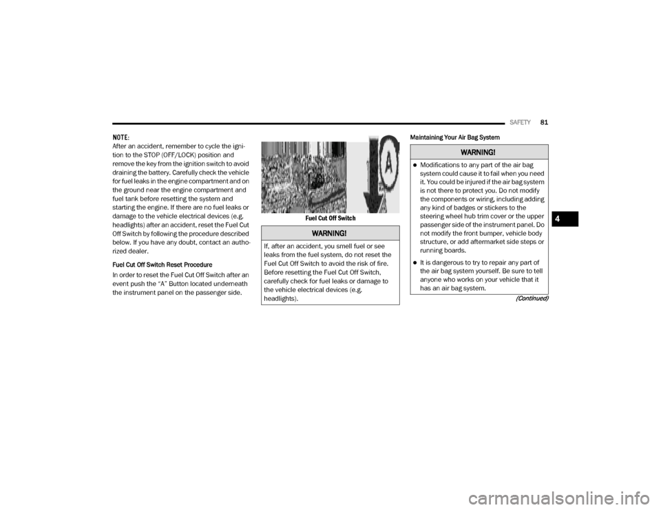
Fuel Cut Off Switch Reset Procedure
In order to reset the Fuel Cut Off Switch after an
event push the “A” Button located underneath
the instrument panel on the passenger side. Fuel Cut Off Switch
Maintaining Your Air Bag System
WARNING!
If, after an accident, you smell fuel or see
leaks from the fuel system, do not reset the
Fuel Cut Off Switch to avoid the risk of fire.
Before resetting the Fuel Cut Off Switch,
carefully check for fuel leaks or damage to
the vehicle electrical devices (e.g.
headlights).
WARNING!
Modifications to any part of the air bag
system could cause it to fail when you need
it. You could be injured if the air bag system
is not there to protect you. Do not modify
the components or wiring, including adding
any kind of badges or stickers to the
steering wheel hub trim cover or the upper
passenger side of the instrument panel. Do
not modify the front bumper, vehicle body
structure, or add aftermarket side steps or
running boards.
It is dangerous to try to repair any part of
the air bag system yourself. Be sure to tell
anyone who works on your vehicle that it
has an air bag system.
4
20_VF_OM_EN_US_t.book Page 81
Page 89 of 264

SAFETY87
Installing Child Restraints In Commercial Vehicles
This commercial vehicle is not designed for use
as a family vehicle and is not intended for
carrying children in the front passenger seat(s).
Never install rear-facing child restraints in this
vehicle. Although the seat belt can be locked to
secure a child restraint, there are no tether
anchorages to complete the proper installation
of a forward-facing child restraint. If you must
carry a child in a forward-facing child restraint,
the passenger seat should be moved to the full
rearward position and the child must be in a
proper restraint system based on its age, size
and weight. Follow the instructions below to
secure the child restraint using the seat belt.
Installing Child Restraints Using The Vehicle Seat
Belt
Child restraint systems are designed to be
secured in vehicle seats by lap belts or the lap
belt portion of a lap/shoulder belt.
The seat belts in the passenger seating posi -
tions are equipped with a Switchable Automatic
Locking Retractor (ALR). This seat belt is
designed to keep the lap portion of the seat belt
tight around the child restraint so that it is not
necessary to use a locking clip. The ALR
retractor can be “switched” into a locked mode
by pulling all of the webbing out of the retractor
and then letting the webbing retract back into
the retractor. If it is locked, the ALR will make a
clicking noise while the webbing is pulled back
into the retractor. Refer to the “Automatic Locking Mode” description in “Switchable Auto
-
matic Locking Retractors (ALR)” under “Occu -
pant Restraint Systems” for additional
information on ALR.
Front Bucket Seat Automatic Locking Retractor (ALR) Location
WARNING!
Rear-facing infant restraints must never be
secured in the passenger seat of a vehicle
with a passenger air bag. In a collision, a
passenger air bag may deploy causing severe
injury or death to infants riding in rear-facing
infant restraints.
WARNING!
Improper installation or failure to properly
secure a child restraint can lead to failure
of the restraint. The child could be badly
injured or killed.
Follow the child restraint manufacturer’s
directions exactly when installing an infant
or child restraint.
ALR — Switchable Automatic Locking Retractor
4
20_VF_OM_EN_US_t.book Page 87
Page 90 of 264

88SAFETY
Front Bench Seat Automatic Locking Retractor (ALR)
Locations
Installing A Child Restraint With A Switchable
Automatic Locking Retractor (ALR)
Child restraint systems are designed to be
secured in vehicle seats by lap belts or the lap
belt portion of a lap/shoulder belt. 1. Place the child seat in the center of the
seating position.
2. Pull enough of the seat belt webbing from the retractor to pass it through the belt path
of the child restraint. Do not twist the belt
webbing in the belt path.
3. Slide the latch plate into the buckle until you hear a “click.”
4. Pull on the webbing to make the lap portion tight against the child seat. 5. To lock the seat belt, pull down on the
shoulder part of the belt until you have
pulled all the seat belt webbing out of the
retractor. Then, allow the webbing to retract
back into the retractor. As the webbing
retracts, you will hear a clicking sound. This
means the seat belt is now in the Automatic
Locking mode.
6. Try to pull the webbing out of the retractor. If it is locked, you should not be able to pull
out any webbing. If the retractor is not
locked, repeat step 5.
7. Finally, pull up on any excess webbing to tighten the lap portion around the child
restraint while you push the child restraint
rearward and downward into the vehicle
seat.
8. Test that the child restraint is installed tightly by pulling back and forth on the child
seat at the belt path. It should not move
more than 1 inch (25.4 mm) in any direc -
tion.
Any seat belt system will loosen with time, so
check the belt occasionally, and pull it tight if
necessary.
ALR — Switchable Automatic Locking Retractor
WARNING!
Improper installation or failure to properly
secure a child restraint can lead to failure
of the restraint. The child could be badly
injured or killed.
Follow the child restraint manufacturer’s
directions exactly when installing an infant
or child restraint.
20_VF_OM_EN_US_t.book Page 88
Page 93 of 264

SAFETY91
(Continued)
Periodic Safety Checks You Should Make
Outside The Vehicle
Tires
Examine tires for excessive tread wear and
uneven wear patterns. Check for stones, nails,
glass, or other objects lodged in the tread or
sidewall. Inspect the tread for cuts and cracks.
Inspect sidewalls for cuts, cracks, and bulges.
Check the wheel bolts for tightness. Check the
tires (including spare) for proper cold inflation
pressure.
Lights
Have someone observe the operation of brake
lights and exterior lights while you work the
controls. Check turn signal and high beam indi -
cator lights on the instrument panel.
Door Latches
Check for proper closing, latching, and locking.
Fluid Leaks
Check area under the vehicle after overnight
parking for fuel, coolant, oil, or other fluid leaks.
Also, if gasoline fumes are detected or if fuel, or
brake fluid leaks are suspected, the cause
should be located and corrected immediately.
ONLY install floor mats designed to fit your
vehicle. NEVER install a floor mat that
cannot be properly attached and secured to
your vehicle. If a floor mat needs to be
replaced, only use a FCA approved floor
mat for the specific make, model, and year
of your vehicle.
ONLY use the driver’s side floor mat on the
driver’s side floor area. To check for inter -
ference, with the vehicle properly parked
with the engine off, fully depress the accel -
erator, the brake, and the clutch pedal (if
present) to check for interference. If your
floor mat interferes with the operation of
any pedal, or is not secure to the floor,
remove the floor mat from the vehicle and
place the floor mat in your trunk.
ONLY use the passenger’s side floor mat on
the passenger’s side floor area.
WARNING!
(Continued)
ALWAYS make sure objects cannot fall or
slide into the driver’s side floor area when
the vehicle is moving. Objects can become
trapped under accelerator, brake, or clutch
pedals and could cause a loss of vehicle
control.
NEVER place any objects under the floor
mat (e.g., towels, keys, etc.). These objects
could change the position of the floor mat
and may cause interference with the accel -
erator, brake, or clutch pedals.
If the vehicle carpet has been removed and
re-installed, always properly attach carpet
to the floor and check the floor mat
fasteners are secure to the vehicle carpet.
Fully depress each pedal to check for inter -
ference with the accelerator, brake, or
clutch pedals then re-install the floor mats.
It is recommended to only use mild soap
and water to clean your floor mats. After
cleaning, always check your floor mat has
been properly installed and is secured to
your vehicle using the floor mat fasteners
by lightly pulling mat.
WARNING!
(Continued)
4
20_VF_OM_EN_US_t.book Page 91
Page 94 of 264
92
STARTING AND OPERATING
STARTING THE ENGINE
Before starting your vehicle, adjust your seat,
adjust both inside and outside mirrors, and
fasten your seat belts.
Automatic Transmission
The gear selector must be in the PARK or
NEUTRAL position before you can start the
engine. Press the brake pedal before shifting to
any driving gear.
NOTE:
You must press the brake pedal before shifting
out of PARK.
Normal Starting
NOTE:
Normal starting of either a cold or a warm
engine is obtained without pumping or pressing
the accelerator pedal.
Turn the ignition switch to the AVV (START) posi-
tion and release it when the engine starts. If the
engine fails to start within 10 seconds, turn the
ignition switch to the STOP (OFF/LOCK) posi -
tion, wait 10 to 15 seconds, then repeat the
“Normal Starting” procedure.
Cold Weather Operation (Below –22°F Or
−30°C)
To ensure reliable starting at these tempera -
tures, use of an externally powered electric
engine block heater (available from your autho -
rized dealer) is recommended.
If Engine Fails To Start
If the engine fails to start after you have
followed the “Normal Starting” procedure, it
may be flooded. Push the accelerator pedal all
the way to the floor and hold it there. Crank the
engine for no more than 15 seconds. This
should clear any excess fuel in case the engine
is flooded. Leave the ignition key in the RUN
position, release the accelerator pedal and
repeat the “Normal Starting” procedure.
WARNING!
Never leave children alone in a vehicle, or
with access to an unlocked vehicle.
Allowing children to be in a vehicle unat -
tended is dangerous for a number of
reasons. A child or others could be seriously
or fatally injured. Children should be
warned not to touch the parking brake,
brake pedal or the transmission gear
selector.
Do not leave the key fob in or near the
vehicle (or in a location accessible to chil -
dren). A child could operate power
windows, other controls, or move the
vehicle.
20_VF_OM_EN_US_t.book Page 92
Page 95 of 264

STARTING AND OPERATING93
After Starting
The idle speed is controlled automatically, and
it will decrease as the engine warms up.
ENGINE BLOCK HEATER — IF EQUIPPED
The engine block heater warms the engine, and
permits quicker starts in cold weather. Connect
the cord to a standard 110-115 Volt AC elec -
trical outlet with a grounded, three-wire exten -
sion cord.
The engine block heater must be plugged in at
least one hour to have an adequate warming
effect on the engine.
ENGINE BREAK-IN RECOMMENDATIONS
A long break-in period is not required for the
engine and drivetrain (transmission and axle) in
your vehicle.
Drive moderately during the first 300 miles
(500 km). After the initial 60 miles (100 km),
speeds up to 50 or 55 mph (80 or 90 km/h) are
desirable.
While cruising, brief full-throttle acceleration
within the limits of local traffic laws contributes
to a good break-in. Wide-open throttle accelera-
tion in low gear can be detrimental and should
be avoided.
WARNING!
Never pour fuel or other flammable liquid
into the throttle body air inlet opening in an
attempt to start the vehicle. This could
result in flash fire causing serious personal
injury.
Do not attempt to push or tow your vehicle
to get it started. Vehicles equipped with an
automatic transmission cannot be started
this way. Unburned fuel could enter the
catalytic converter and once the engine has
started, ignite and damage the converter
and vehicle.
If the vehicle has a discharged battery,
booster cables may be used to obtain a
start from a booster battery or the battery in
another vehicle. This type of start can be
dangerous if done improperly. Refer to
“Jump Starting Procedure” in “In Case Of
Emergency” for further information.
CAUTION!
To prevent damage to the starter, do not
continuously crank the engine for more than
25 seconds at a time. Wait 60 seconds
before trying again.
WARNING!
Remember to disconnect the engine block
heater cord before driving. Damage to the
110-115 Volt electrical cord could cause
electrocution.
5
20_VF_OM_EN_US_t.book Page 93
Page 96 of 264
94STARTING AND OPERATING
(Continued)
The engine oil installed in the engine at the
factory is a high-quality energy conserving type
lubricant. Oil changes should be consistent with
anticipated climate conditions under which
vehicle operations will occur. For the recom -
mended viscosity and quality grades, refer to
“Fluids And Lubricants” in “Technical Specifica-
tions”.
NOTE:
A new engine may consume some oil during its
first few thousand miles (kilometers) of opera -
tion. This should be considered a normal part of
the break-in and not interpreted as a problem.
Please check your oil level with the engine oil
indicator often during the break in period. Add
oil as required.PARKING BRAKE
Before leaving the vehicle, make sure that the
parking brake is fully applied.
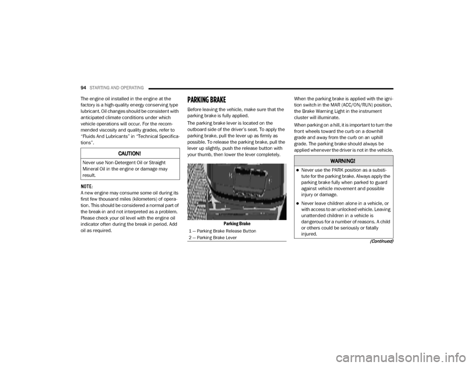
The parking brake lever is located on the
outboard side of the driver’s seat. To apply the
parking brake, pull the lever up as firmly as
possible. To release the parking brake, pull the
lever up slightly, push the release button with
your thumb, then lower the lever completely.
Parking Brake When the parking brake is applied with the igni
-
tion switch in the MAR (ACC/ON/RUN) position,
the Brake Warning Light in the instrument
cluster will illuminate.
When parking on a hill, it is important to turn the
front wheels toward the curb on a downhill
grade and away from the curb on an uphill
grade. The parking brake should always be
applied whenever the driver is not in the vehicle.
CAUTION!
Never use Non-Detergent Oil or Straight
Mineral Oil in the engine or damage may
result.
1 — Parking Brake Release Button
2 — Parking Brake Lever
WARNING!
Never use the PARK position as a substi -
tute for the parking brake. Always apply the
parking brake fully when parked to guard
against vehicle movement and possible
injury or damage.
Never leave children alone in a vehicle, or
with access to an unlocked vehicle. Leaving
unattended children in a vehicle is
dangerous for a number of reasons. A child
or others could be seriously or fatally
injured.
20_VF_OM_EN_US_t.book Page 94
Page 97 of 264
STARTING AND OPERATING95
(Continued)
AUTOMATIC TRANSMISSION
Do not leave the key fob in or near the
vehicle, or in a location accessible to chil-
dren, and do not leave a vehicle equipped
with Keyless Enter-N-Go in the ACC or ON/
RUN mode. A child could operate power
windows, other controls, or move the
vehicle.
Be sure the parking brake is fully disen -
gaged before driving; failure to do so can
lead to brake failure and a collision.
Always fully apply the parking brake when
leaving your vehicle or it may roll and cause
damage or injury. Also, be certain to leave
the transmission in PARK. Failure to do so
may cause the vehicle to roll and cause
damage or injury.
CAUTION!
If the Brake System Warning Light remains on
with the parking brake released, a brake
system malfunction is indicated. Have the
brake system serviced by an authorized
dealer immediately.
WARNING!
(Continued)
WARNING!
It is dangerous to shift out of PARK or
NEUTRAL if the engine speed is higher than
idle speed. If your foot is not firmly pressing
the brake pedal, the vehicle could accel -
erate quickly forward or in reverse. You
could lose control of the vehicle and hit
someone or something. Only shift into gear
when the engine is idling normally and your
foot is firmly pressing the brake pedal.
Unintended movement of a vehicle could
injure those in or near the vehicle. As with
all vehicles, you should never exit a vehicle
while the engine is running. Before exiting a
vehicle always come to a complete stop,
then apply the parking brake, shift the
transmission into PARK, turn the engine
OFF, and remove the ignition key. Once the
key is removed, the transmission is locked
in PARK, securing the vehicle against
unwanted movement.
When leaving the vehicle, always remove
the ignition key from the vehicle and lock
the vehicle.
Never leave children alone in a vehicle, or
with access to an unlocked vehicle.
Allowing children to be in a vehicle unat -
tended is dangerous for a number of
reasons. A child or others could be seriously
or fatally injured. Children should be
warned not to touch the parking brake,
brake pedal or the transmission gear
selector.
Do not leave the ignition key in or near the
vehicle (or in a location accessible to chil -
dren). A child could operate power
windows, other controls, or move the
vehicle.
WARNING!
(Continued)
5
20_VF_OM_EN_US_t.book Page 95
Page 98 of 264
96STARTING AND OPERATING
NOTE:
You must press and hold the brake pedal while
shifting out of PARK.
Key Ignition Park Interlock
This vehicle is equipped with a Key Ignition Park
Interlock which requires the transmission to be
in PARK before the ignition can be turned to the
LOCK/OFF (key removal) position. The key can
only be removed from the ignition when the igni -
tion is in the LOCK/OFF position, and once
removed the transmission is locked in PARK. NOTE:
If a malfunction occurs, the system will trap the
key in the ignition to warn you that this safety
feature is inoperable. The engine can be started
and stopped but the key cannot be removed
until you obtain service.
Brake/Transmission Shift Interlock System
This vehicle is equipped with a Brake Transmis
-
sion Shift Interlock System (BTSI) that holds the
transmission gear selector in PARK unless the
brakes are applied. To shift the transmission
out of PARK, the ignition must be turned to the
ON/RUN mode (engine running or not), and the
brake pedal must be pressed.
NOTE:
Swivel seats that are unlocked can also prevent
the transmission gear selector from being
moved out of the PARK position. To shift the
transmission out of the PARK position the first
time after cranking is allowed, ensure swivel
seats are locked in the forward facing position.
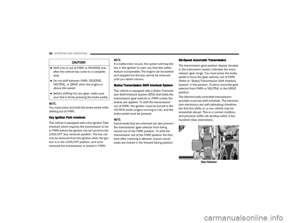
Six-Speed Automatic Transmission
The transmission gear position display (located
in the instrument cluster) indicates the trans -
mission gear range. You must press the brake
pedal to move the gear selector out of PARK
(Refer to “Brake/Transmission Shift Interlock
System” in this section). To drive, move the gear
selector from PARK or NEUTRAL to the DRIVE
position.
The electronically-controlled transmission
provides a precise shift schedule. The transmis -
sion electronics are self-calibrating; therefore,
the first few shifts on a new vehicle may be
somewhat abrupt. This is a normal condition,
and precision shifts will develop within a few
hundred miles (kilometers).
Gear SelectorCAUTION!
Shift into or out of PARK or REVERSE only
after the vehicle has come to a complete
stop.
Do not shift between PARK, REVERSE,
NEUTRAL, or DRIVE when the engine is
above idle speed.
Before shifting into any gear, make sure
your foot is firmly pressing the brake pedal.
20_VF_OM_EN_US_t.book Page 96