lock Ram ProMaster 2020 User Guide
[x] Cancel search | Manufacturer: RAM, Model Year: 2020, Model line: ProMaster, Model: Ram ProMaster 2020Pages: 264, PDF Size: 10.11 MB
Page 23 of 264
GETTING TO KNOW YOUR VEHICLE21
STEERING WHEEL
Telescoping Steering Column
This feature allows you to lengthen or shorten
the steering column. The telescoping control
handle is located below the steering wheel at
the end of the steering column.
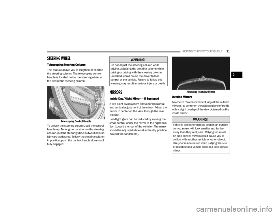
Telescoping Control Handle
To unlock the steering column, pull the control
handle up. To lengthen or shorten the steering
column, pull the steering wheel outward or push
it inward as desired. To lock the steering column
in position, push the control handle down until
fully engaged.
MIRRORS
Inside Day/Night Mirror — If Equipped
A two-point pivot system allows for horizontal
and vertical adjustment of the mirror. Adjust the
mirror to center on the view through the rear
window.
Headlight glare can be reduced by moving the
small control under the mirror to the night posi -
tion (toward the rear of the vehicle). The mirror
should be adjusted while set in the day position
(toward the windshield). Adjusting Rearview Mirror
Outside Mirrors
To receive maximum benefit, adjust the outside
mirror(s) to center on the adjacent lane of traffic
with a slight overlap of the view obtained on the
inside mirror.
WARNING!
Do not adjust the steering column while
driving. Adjusting the steering column while
driving or driving with the steering column
unlocked, could cause the driver to lose
control of the vehicle. Failure to follow this
warning may result in serious injury or death.
WARNING!
Vehicles and other objects seen in an outside
convex mirror will look smaller and farther
away than they really are. Relying too much
on side convex mirrors could cause you to
collide with another vehicle or other object.
Use your inside mirror when judging the size
or distance of a vehicle seen in a side convex
mirror.
2
20_VF_OM_EN_US_t.book Page 21
Page 26 of 264
24GETTING TO KNOW YOUR VEHICLE
Daytime Running Lights (DRLs) — If
Equipped
NOTE:
When the headlights are turned on, the Daytime
Running Lights will be deactivated.
To activate the Daytime Running Lights (DRLs),
rotate the end of the multifunction lever to the
O (off) position.
NOTE:
The low beams and side/taillights will not be
on with DRLs.
In certain markets, the DRLs may be optional
and can be programmed to be on or off
through the Uconnect system screen. Refer
to “Uconnect Settings” in “Multimedia” for
further information.
The Daytime Running Lights will come on when -
ever the ignition is ON, the headlight switch is
off, and the turn signal is off.
High Beam/Low Beam Select Switch
With the low beams activated, pull the multi -
function lever toward the steering wheel to
switch the headlights to high beam. A high
beam symbol will be illuminated in the cluster to
indicate the high beams are on. Pull the lever a
second time to switch the headlights back to
low beam.
NOTE:
If the vehicle’s ignition is placed in the STOP
(OFF/LOCK) position, both high and low beam
headlights will also be turned off.
Flash-To-Pass
You can signal another vehicle with your head -
lights by partially pulling the multifunction lever
toward the steering wheel. This will cause the
high beam headlights to turn on until the lever
is released.
Parking Lights
These lights can only be turned on with ignition
key in the STOP (OFF/LOCK) position or
removed, by moving the end of the multifunc -
tion lever to O (off) position and then to the
headlight position. The warning light telltale in the instrument
panel comes on. The lights stay on until the next
ignition cycle is performed.
Follow Me Home/Headlight Delay
When this feature is selected, the driver can
choose to have the headlights remain on for a
preset period of time.
Activation
Remove the key or turn the ignition to the STOP
(OFF/LOCK) position, and pull the multifunction
lever toward the steering wheel, within two
minutes. Each time the lever is pulled, the acti
-
vation of the lights will be extended by 30
seconds. The activation of the lights can be
extended to a maximum of 210 seconds.
The warning light on the instrument panel will
light up and the corresponding message will
appear in the instrument cluster display for as
long as the function is activated. The warning
light comes on when the lever is operated and
stays on until the function is automatically deac -
tivated. Each movement of the lever only
increases the amount of time the lights stay on.
Deactivation
Pull the multifunction lever toward the steering
wheel and hold it for more than two seconds.
20_VF_OM_EN_US_t.book Page 24
Page 27 of 264
GETTING TO KNOW YOUR VEHICLE25
Fog Lights — If Equipped
The fog light switch is located on the center
stack of the instrument panel, just below the
climate controls. Push the switch once to turn
the fog lights on. Push the switch a second time
to turn the fog lights off.
NOTE:
If the vehicle’s ignition is placed in the STOP
(OFF/LOCK) position, the fog lights will also turn
off.
Turn Signals
Move the multifunction lever up or down and
the arrows on each side of the instrument
cluster flash to show proper operation of the
front and rear turn signal lights.
NOTE:
If either light remains on and does not flash, or
there is a very fast flash rate, check for a defec -
tive outside light bulb. If an indicator fails to
light when the lever is moved, it would suggest
that the indicator bulb is defective.
Lane Change Assist
Tap the lever up or down once, without moving
beyond the detent, and the turn signal (right or
left) will flash five times then automatically turn
off.
Battery Saver
To protect the life of your vehicle’s battery,
when the ignition is OFF and any door is left ajar
for 15 minutes, the interior lights will automati -
cally turn off.
NOTE:
Battery saver mode is cancelled if the ignition is
placed in the MAR (ACC/ON/RUN).
INTERIOR LIGHTS
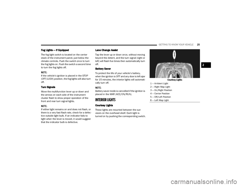
Courtesy Lights
These lights are mounted between the sun
visors on the overhead shelf. Each light is
turned on by pushing the corresponding switch. Courtesy Lights
1 — Ambient Light
2 — Right Map Light
3 — On/Right Position
4 — Center Position
5 — Off/Left Position
6 — Left Map Light
2
20_VF_OM_EN_US_t.book Page 25
Page 29 of 264
GETTING TO KNOW YOUR VEHICLE27
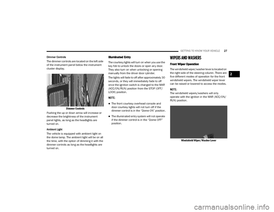
Dimmer Controls
The dimmer controls are located on the left side
of the instrument panel below the instrument
cluster display.
Dimmer Controls
Pushing the up or down arrow will increase or
decrease the brightness of the instrument
panel lights, as long as the headlights are
turned on.
Ambient Light
The vehicle is equipped with ambient light on
the dome lamp. The ambient light will be on all
the time, with the option of dimming it with the
dimmer controls as long as the headlights are
turned on.
Illuminated Entry
The courtesy lights will turn on when you use the
key fob to unlock the doors or open any door.
They also turn on when unlocking or opening
manually from the driver door cylinder.
The lights will fade to off after approximately 30
seconds, or they will immediately fade to off
once the ignition switch is changed to the MAR
(ACC/ON/RUN) position from the STOP (OFF/
LOCK) position.
NOTE:
The front courtesy overhead console and
door courtesy lights will not turn off if the
dimmer control is in the “Dome ON” position.
The illuminated entry system will not operate
if the dimmer control is in the “Dome OFF”
position.
WIPERS AND WASHERS
Front Wiper Operation
The windshield wiper/washer lever is located on
the right side of the steering column. There are
five different modes of operation for the front
windshield wipers. The windshield wiper lever
can be raised or lowered to access the modes.
NOTE:
The windshield wipers/washers will only
operate with the ignition in the MAR (ACC/ON/
RUN) position.
Windshield Wiper/Washer Lever
2
20_VF_OM_EN_US_t.book Page 27
Page 31 of 264
GETTING TO KNOW YOUR VEHICLE29
Manual Climate Control Descriptions
Icon Description
A/C Button
Push the A/C button to engage the Air Conditioning (A/C). The A/C indicator illuminates when A/C is on.
Recirculation Button
Press and release this button to change the system between recirculation mode and outside air mode. The Recirculation
indicator and the A/C indicator illuminate when the Recirculation button is pressed. Recirculation can be used when
outside conditions such as smoke, odors, dust, or high humidity are present. Recirculation can be used in all modes except
for Defrost. Recirculation may be unavailable if conditions exist that could create fogging on the inside of the windshield.
The A/C can be deselected manually without disturbing the mode control selection. Continuous use of the Recirculation
mode may make the inside air stuffy and window fogging may occur. Extended use of this mode is not recommended.
Front Defrost Mode
Turn the mode control knob to the Front Defrost position. Air comes from the windshield and side window demist outlets.
When the defrost button is selected, the blower level may increase. Use Defrost mode with maximum temperature settings
for best windshield and side window defrosting and defogging.
Rear Defrost Button
Push and release the Rear Defrost Control button to turn on the rear window defroster and the heated outside mirrors (if
equipped). The Rear Defrost indicator illuminates when the rear window defroster is ON. The rear window defroster
automatically turns OFF after 15 minutes.
Temperature Control
Temperature Control regulates the temperature of the air forced through the climate system. The temperature increases as
you turn the temperature control knob clockwise. The temperature decreases as you turn the temperature control knob
counterclockwise.
2
20_VF_OM_EN_US_t.book Page 29
Page 32 of 264
30GETTING TO KNOW YOUR VEHICLE
Blower Control
Blower Control regulates the amount of air forced through the climate system. There are seven blower speeds available.
The blower speed increases as you turn the blower control knob clockwise from the lowest blower setting. The blower
speed decreases as you turn the blower control knob counterclockwise.
NOTE:
Depending on the configuration, your vehicle may be equipped with four blower speeds.
Mode Control
Turn the mode control knob to change the airflow distribution mode. The airflow distribution mode can be adjusted so air
comes from the instrument panel outlets, floor outlets, defrost outlets and demist outlets. The Mode settings are as
follows:
Panel Mode Panel Mode Air comes from the outlets in the instrument panel. Each of these outlets can be individually adjusted to direct the flow of
air. The air vanes of the center outlets and outboard outlets can be moved up and down or side to side to regulate airflow
direction. There is a shut off wheel located below the air vents to shut off or adjust the amount of airflow from these
outlets.
Icon Description
20_VF_OM_EN_US_t.book Page 30
Page 37 of 264
GETTING TO KNOW YOUR VEHICLE35
WINDOWS
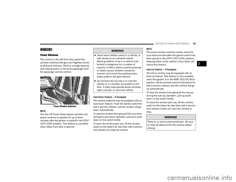
Power Windows
The control on the left front door panel has
up-down switches that give you fingertip control
of all power windows. There is a single opening
and closing switch on the front passenger door
for passenger window control.
Power Window Switches
NOTE:
The Key Off Power Delay feature will allow the
power windows to operate for up to three
minutes after the ignition is placed in the STOP
(OFF/LOCK) position. This feature is cancelled
when either front door is opened.
Auto-Down Feature — If Equipped
The window switches may be equipped with an
Auto-Down feature. Push the window switch for
half a second, release, and the window will go
down automatically.
To stop the window from going all the way down
during the auto-down operation, pull up or push
down on the switch briefly.
To open the window part way, lift the window
switch to the detent for less than half a second
and release it to stop the window. NOTE:
The power window switches remain active for
up to three minutes after the ignition switch has
been placed in the STOP (OFF/LOCK) position.
Opening either of the vehicle’s front doors will
cancel this feature.
Auto-Up Feature — If Equipped
The driver window may be equipped with an
Auto-Up feature. This feature is only available
when the ignition is in the MAR (ACC/ON/RUN)
position. Lift the window switch to the detent for
half a second, release, and the window will go
up automatically.
To stop the window from going all the way up
during the auto-up operation, pull up/push
down on the switch briefly.
To close the window part way, lift the window
switch to the detent for less than half a second
and release it when you want the window to
stop.
WARNING!
Never leave children alone in a vehicle, or
with access to an unlocked vehicle.
Allowing children to be in a vehicle unat
-
tended is dangerous for a number of
reasons. A child or others could be seriously
or fatally injured. Children should be
warned not to touch the parking brake,
brake pedal or the gear selector.
Do not leave the key fob in or near the
vehicle or in a location accessible to chil -
dren. A child could operate power windows,
other controls, or move the vehicle.
WARNING!
There is no auto-reverse protection. Be sure
to clear all objects from the window before
closing.
2
20_VF_OM_EN_US_t.book Page 35
Page 39 of 264

GETTING TO KNOW YOUR VEHICLE37
3. Raise the hood and place the hood prop rod
in hood slot to secure the hood in the open
position.
Hood Prop Rod Slot
ClosingCARGO AREA FEATURES
The cargo area may be equipped with different
options such as optional side panels, rear seats
and an optional floor.
INTERNAL EQUIPMENT
Storage
Glove Compartments
The glove compartment is located on the
passenger side of the instrument panel and
features both an upper and lower storage area. Glove Compartments
Front Door Storage — If Equipped
Storage areas and bottle holders are located in
both the front door trim panels.
Front Door Storage
WARNING!
Be sure the hood is fully latched before
driving your vehicle. If the hood is not fully
latched, it could open when the vehicle is in
motion and block your vision. Failure to follow
this warning could result in serious injury or
death.
CAUTION!
To prevent possible damage:
Before closing hood, make sure the hood
prop rod is fully seated into its storage
retaining clips.
Do not slam the hood to close it. Use a firm
downward push at the center front edge of
the hood to ensure that both latches
engage. Never drive your vehicle unless the
hood is fully closed, with both latches
engaged.
1 — Upper Glove Compartment
2 — Lower Glove Compartment
2
20_VF_OM_EN_US_t.book Page 37
Page 45 of 264
GETTING TO KNOW YOUR INSTRUMENT PANEL43
5. Fuel Gauge
The pointer shows the level of fuel in the
fuel tank when the ignition switch is in
the ON/RUN position.
The fuel pump symbol points to the
side of the vehicle where the fuel door is
located.
INSTRUMENT CLUSTER DISPLAY
Your vehicle will be equipped with an instru -
ment cluster display, which offers useful infor -
mation to the driver. With the ignition in the
STOP (OFF/LOCK) mode, opening/closing of a
door will activate the display for viewing, and
display the total miles, or kilometers, in the
odometer. Your instrument cluster display is
designed to display important information
about your vehicle’s systems and features.
Using a driver interactive display located on the
instrument panel, your instrument cluster
display can show you how systems are working
and give you warnings when they are not. The
steering wheel mounted controls allow you to
scroll through the main menus and submenus.
You can access the specific information you
want and make selections and adjustments.
Location And Controls
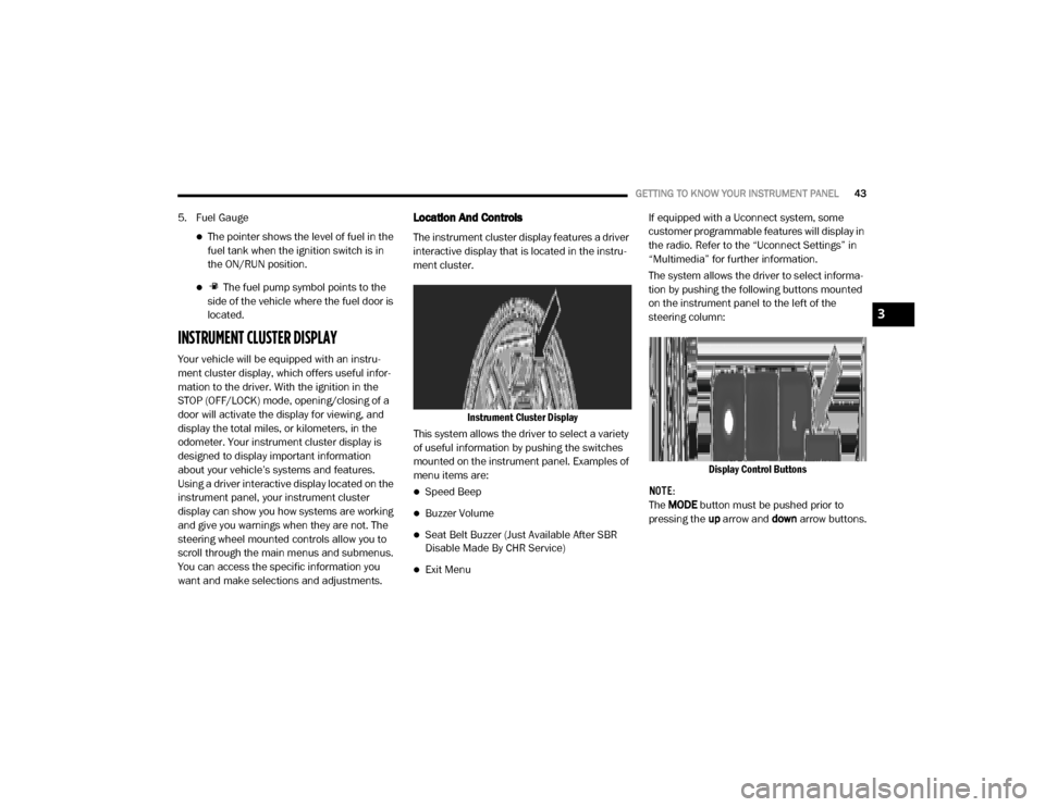
The instrument cluster display features a driver
interactive display that is located in the instru -
ment cluster.
Instrument Cluster Display
This system allows the driver to select a variety
of useful information by pushing the switches
mounted on the instrument panel. Examples of
menu items are:
Speed Beep
Buzzer Volume
Seat Belt Buzzer (Just Available After SBR
Disable Made By CHR Service)
Exit Menu If equipped with a Uconnect system, some
customer programmable features will display in
the radio. Refer to the “Uconnect Settings” in
“Multimedia” for further information.
The system allows the driver to select informa
-
tion by pushing the following buttons mounted
on the instrument panel to the left of the
steering column:
Display Control Buttons
NOTE:
The MODE button must be pushed prior to
pressing the up arrow and down arrow buttons.
3
20_VF_OM_EN_US_t.book Page 43
Page 46 of 264
44GETTING TO KNOW YOUR INSTRUMENT PANEL
MODE Button
Push and hold the MODE button for a time
longer than one second to access/select the
information screens or submenu screens of a
main menu item. Push and hold the MODE
button for two seconds to reset displayed/
selected features that can be reset.
Up Arrow Button
Push and release the up arrow
button to scroll upward through the
main menu and submenus or
adjust the illumination on the
instrument panel when the headlights are on.
Down Arrow Button
Push and release the down arrow
button to scroll downward through
the main menu and submenus or
adjust the illumination on the
instrument panel when the headlights are on.
Change Engine Oil
Your vehicle is equipped with an engine oil
change indicator system. The “Change Engine
Oil” message will display in the instrument
cluster display. The engine oil change indicator
system is duty cycle based, which means the engine oil change interval may fluctuate, depen
-
dent upon your personal driving style.
Unless reset, this message will continue to
display each time you turn the ignition switch to
the ON/RUN position. To turn off the message
temporarily, push and release the MODE
button. To reset the oil change indicator system
(after performing the scheduled maintenance),
refer to the following procedure.
1. Turn the ignition switch to the ON position (do not start the engine).
2. Fully push the accelerator pedal slowly, three times, within 10 seconds.
3. Turn the ignition switch to the OFF/LOCK position.
NOTE:
If the indicator message illuminates when you
start the vehicle, the oil change indicator
system did not reset. If necessary, repeat this
procedure.Display Setup Menu
The menu comprises a series of functions
arranged in a cycle. Push and release the up or
down arrow button to access the different
options and settings (setup). The setup menu can be activated by pushing
the
MODE button. Single pushes on the up or
down arrow button will scroll through the setup
menu options. The menu items include the
following functions:
Speed Beep
Buzzer Volume
Seat Belt Buzzer (Just Available After SBR
Disable Made By CHR Service)
Exit menu
NOTE:
If equipped, some customer programmable
features will display in the Uconnect system.
Refer to your Uconnect Owner’s Manual Supple -
ment for further information.
Selecting An Option Of The Main Menu Without
Submenu
1. Briefly push and release the MODE button
to select the main menu option to set.
2. Push and release the up or down arrow
button (by single pushes) to select the new
setting.
20_VF_OM_EN_US_t.book Page 44