Outlet Ram ProMaster 2020 Owner's Manual
[x] Cancel search | Manufacturer: RAM, Model Year: 2020, Model line: ProMaster, Model: Ram ProMaster 2020Pages: 264, PDF Size: 10.11 MB
Page 4 of 264

2
INTRODUCTION
INTRODUCTION ......................................................... 7
HOW TO USE THIS MANUAL ................................... 8
Essential Information ........................................... 8
Symbols ................................................................. 8
WARNINGS AND CAUTIONS ................................... 8
VAN CONVERSIONS/CAMPERS .............................. 8
VEHICLE MODIFICATIONS/ALTERATIONS ............. 8
GETTING TO KNOW YOUR VEHICLE
KEYS .......................................................................... 9
Key Fob ................................................................. 9
IGNITION SWITCH ................................................... 11
Mechanical Ignition Switch ................................ 11
Key-In-Ignition Reminder ................................... 12
SENTRY KEY............................................................. 12
Replacement Keys ............................................ 12
General Information ........................................... 12
VEHICLE SECURITY ALARM — IF EQUIPPED ....... 13
To Arm The System ............................................. 13
To Disarm The System ....................................... 13
Rearming Of The System ................................... 14
Security System Manual Override ..................... 14
DOORS ..................................................................... 14
Power Door Locks .............................................. 14
Auto Unlock Doors .............................................. 15
Automatic Door Locks ........................................ 15
SEATS .......................................................................15
Manual Adjustments .......................................... 15
Heated Seats — If Equipped .............................. 18
Fold Down Tray — If Equipped ........................... 19
Adjustable Armrests — If Equipped ................... 19
HEAD RESTRAINTS ................................................20
Front Head Restraint Adjustment ..................... 20
Front Head Restraint Removal .......................... 20
STEERING WHEEL ...................................................21
Telescoping Steering Column ............................ 21
MIRRORS .................................................................21
Inside Day/Night Mirror — If Equipped ............ 21
Outside Mirrors .................................................. 21
Power Mirrors — If Equipped ............................. 22
Power Folding Mirrors — If Equipped ................ 22
Heated Mirrors — If Equipped............................ 23
EXTERIOR LIGHTS ...................................................23
Multifunction Lever ........................................... 23
Headlights .......................................................... 23
Daytime Running Lights (DRLs) —
If Equipped ......................................................... 24 High Beam/Low Beam Select Switch .............. 24
Flash-To-Pass ..................................................... 24
Parking Lights .................................................... 24
Follow Me Home/Headlight Delay .................... 24
Fog Lights — If Equipped ................................... 25
Turn Signals ........................................................ 25
Lane Change Assist............................................ 25
Battery Saver ...................................................... 25
INTERIOR LIGHTS ................................................... 25
Courtesy Lights....................................................25
Illuminated Entry .................................................27
WIPERS AND WASHERS ........................................ 27
Front Wiper Operation .......................................27
CLIMATE CONTROLS .............................................. 28
Manual Climate Control Overview......................28
Climate Control Functions ..................................33
Operating Tips .....................................................33
WINDOWS ............................................................... 35
Power Windows ..................................................35
Window Bar Grates — If Equipped .....................36
Wind Buffeting ....................................................36
HOOD ........................................................................ 36
Opening ...............................................................36
Closing .................................................................37
CARGO AREA FEATURES ....................................... 37
INTERNAL EQUIPMENT .......................................... 37
Storage ................................................................37
Cupholders ..........................................................38
Power Outlets ......................................................39
Auxiliary Switches — If Equipped ........................40
20_VF_OM_EN_US_t.book Page 2
Page 31 of 264
GETTING TO KNOW YOUR VEHICLE29
Manual Climate Control Descriptions
Icon Description
A/C Button
Push the A/C button to engage the Air Conditioning (A/C). The A/C indicator illuminates when A/C is on.
Recirculation Button
Press and release this button to change the system between recirculation mode and outside air mode. The Recirculation
indicator and the A/C indicator illuminate when the Recirculation button is pressed. Recirculation can be used when
outside conditions such as smoke, odors, dust, or high humidity are present. Recirculation can be used in all modes except
for Defrost. Recirculation may be unavailable if conditions exist that could create fogging on the inside of the windshield.
The A/C can be deselected manually without disturbing the mode control selection. Continuous use of the Recirculation
mode may make the inside air stuffy and window fogging may occur. Extended use of this mode is not recommended.
Front Defrost Mode
Turn the mode control knob to the Front Defrost position. Air comes from the windshield and side window demist outlets.
When the defrost button is selected, the blower level may increase. Use Defrost mode with maximum temperature settings
for best windshield and side window defrosting and defogging.
Rear Defrost Button
Push and release the Rear Defrost Control button to turn on the rear window defroster and the heated outside mirrors (if
equipped). The Rear Defrost indicator illuminates when the rear window defroster is ON. The rear window defroster
automatically turns OFF after 15 minutes.
Temperature Control
Temperature Control regulates the temperature of the air forced through the climate system. The temperature increases as
you turn the temperature control knob clockwise. The temperature decreases as you turn the temperature control knob
counterclockwise.
2
20_VF_OM_EN_US_t.book Page 29
Page 32 of 264
30GETTING TO KNOW YOUR VEHICLE
Blower Control
Blower Control regulates the amount of air forced through the climate system. There are seven blower speeds available.
The blower speed increases as you turn the blower control knob clockwise from the lowest blower setting. The blower
speed decreases as you turn the blower control knob counterclockwise.
NOTE:
Depending on the configuration, your vehicle may be equipped with four blower speeds.
Mode Control
Turn the mode control knob to change the airflow distribution mode. The airflow distribution mode can be adjusted so air
comes from the instrument panel outlets, floor outlets, defrost outlets and demist outlets. The Mode settings are as
follows:
Panel Mode Panel Mode Air comes from the outlets in the instrument panel. Each of these outlets can be individually adjusted to direct the flow of
air. The air vanes of the center outlets and outboard outlets can be moved up and down or side to side to regulate airflow
direction. There is a shut off wheel located below the air vents to shut off or adjust the amount of airflow from these
outlets.
Icon Description
20_VF_OM_EN_US_t.book Page 30
Page 33 of 264

GETTING TO KNOW YOUR VEHICLE31
Bi-Level Mode Bi-Level Mode
Air comes from the instrument panel outlets and floor outlets. A slight amount of air is directed through the defrost and
side window demister outlets.
NOTE:
Bi-Level mode is designed under comfort conditions to provide cooler air out of the panel outlets and warmer air from the
floor outlets.
Floor Mode Floor Mode Air comes from the floor outlets. A slight amount of air is directed through the defrost and side window demister outlets.
Mix Mode Mix Mode Air is directed through the floor, defrost, and side window demister outlets. This setting works best in cold or snowy
conditions that require extra heat to the windshield. This setting is good for maintaining comfort while reducing moisture on
the windshield.
Icon Description
2
20_VF_OM_EN_US_t.book Page 31
Page 35 of 264

GETTING TO KNOW YOUR VEHICLE33
Climate Control Functions
A/C (Air Conditioning)
The Air Conditioning (A/C) button allows the
operator to manually activate or deactivate the
air conditioning system. When the air condi -
tioning system is turned on, cool dehumidified
air will flow through the outlets into the cabin.
For improved fuel economy, press the A/C
button to turn off the air conditioning and manu -
ally adjust the blower and airflow mode settings.
Also, make sure to select only Panel, Bi-Level or
Floor modes.
NOTE:
For Manual Climate Controls, if the system is
in Mix, Floor or Defrost Mode, the A/C can be
turned off, but the A/C system shall remain
active to prevent fogging of the windows.
If fog or mist appears on the windshield or
side glass, select Defrost mode, and increase
blower speed if needed.
If your air conditioning performance seems
lower than expected, check the front of the
A/C condenser (located in front of the radi -
ator), for an accumulation of dirt or insects.
Clean with a gentle water spray from the front
of the radiator and through the condenser.
Recirculation
In cold weather, use of Recirculation mode may
lead to excessive window fogging. The Recircu -
lation feature may be unavailable if conditions
exist that could create fogging on the inside of
the windshield. On systems with Manual
Climate Controls, the Recirculation mode is not
allowed in Defrost mode to improve window
clearing operation. Recirculation is disabled
automatically if this mode is selected.
Attempting to use Recirculation while in this
mode causes the LED in the control button to
blink and then turns off.
Operating Tips
NOTE:
Refer to the chart at the end of this section for
suggested control settings for various weather
conditions.
Summer Operation
The engine cooling system must be protected
with a high-quality antifreeze coolant to provide
proper corrosion protection and to protect
against engine overheating. A solution of 50%
OAT (Organic Additive Technology) coolant that
meets the requirements of FCA Material Stan -dard MS.90032 and 50% water is recom
-
mended. Refer to “Fluids And Lubricants” in
“Technical Specifications” for proper coolant
selection.
Winter Operation
Use of the air Recirculation mode during Winter
months is not recommended because it may
cause window fogging.
Vacation Storage
Any time you store your vehicle or keep it out of
service (i.e., vacation) for two weeks or more,
run the air conditioning system at idle for about
five minutes in the fresh air and high blower
setting. This will ensure adequate system lubri -
cation to minimize the possibility of compressor
damage when the system is started again.
Window Fogging
Interior fogging on the windshield can be quickly
removed by turning the mode selector to
Defrost. The Defrost/Floor mode can be used to
maintain a clear windshield and provide suffi -
cient heating. If side window fogging becomes a
problem increase blower speed. Vehicle
windows tend to fog on the inside in mild but
rainy or humid weather.
2
20_VF_OM_EN_US_t.book Page 33
Page 41 of 264
GETTING TO KNOW YOUR VEHICLE39
Power Outlets
Passenger Compartment Power Outlet
The power outlet is located on the instrument
panel passenger compartment near the cup
holder. It only operates with the ignition key at
MAR (ACC/ON/RUN).
Passenger Compartment Power Outlet Load Compartment Power Outlet — If Equipped
The load compartment power outlet is located
in rear cargo compartment. The outlet can be is
used for powering 12 Volt adaptive accessories
and recharging communications devices.
Load Compartment Power Outlet
NOTE:
Do not connect devices with power higher than
180 W to the socket. Do not damage the socket
by using unsuitable adaptors. Power Outlet Fuses — Under Hood
1 — F14 Fuse 20 Amp Yellow Front Power Outlet
2 — F09 Fuse 15 Amp Blue Rear Power Outlet
WARNING!
To avoid serious injury or death:
Only devices designed for use in this type of
outlet should be inserted into any 12 Volt
outlet.
Do not touch with wet hands.
Close the lid when not in use and while
driving the vehicle.
If this outlet is mishandled, it may cause an
electric shock and failure.
2
20_VF_OM_EN_US_t.book Page 39
Page 95 of 264
STARTING AND OPERATING93
After Starting
The idle speed is controlled automatically, and
it will decrease as the engine warms up.
ENGINE BLOCK HEATER — IF EQUIPPED
The engine block heater warms the engine, and
permits quicker starts in cold weather. Connect
the cord to a standard 110-115 Volt AC elec -
trical outlet with a grounded, three-wire exten -
sion cord.
The engine block heater must be plugged in at
least one hour to have an adequate warming
effect on the engine.
ENGINE BREAK-IN RECOMMENDATIONS
A long break-in period is not required for the
engine and drivetrain (transmission and axle) in
your vehicle.
Drive moderately during the first 300 miles
(500 km). After the initial 60 miles (100 km),
speeds up to 50 or 55 mph (80 or 90 km/h) are
desirable.
While cruising, brief full-throttle acceleration
within the limits of local traffic laws contributes
to a good break-in. Wide-open throttle accelera-
tion in low gear can be detrimental and should
be avoided.
WARNING!
Never pour fuel or other flammable liquid
into the throttle body air inlet opening in an
attempt to start the vehicle. This could
result in flash fire causing serious personal
injury.
Do not attempt to push or tow your vehicle
to get it started. Vehicles equipped with an
automatic transmission cannot be started
this way. Unburned fuel could enter the
catalytic converter and once the engine has
started, ignite and damage the converter
and vehicle.
If the vehicle has a discharged battery,
booster cables may be used to obtain a
start from a booster battery or the battery in
another vehicle. This type of start can be
dangerous if done improperly. Refer to
“Jump Starting Procedure” in “In Case Of
Emergency” for further information.
CAUTION!
To prevent damage to the starter, do not
continuously crank the engine for more than
25 seconds at a time. Wait 60 seconds
before trying again.
WARNING!
Remember to disconnect the engine block
heater cord before driving. Damage to the
110-115 Volt electrical cord could cause
electrocution.
5
20_VF_OM_EN_US_t.book Page 93
Page 131 of 264
IN CASE OF EMERGENCY129
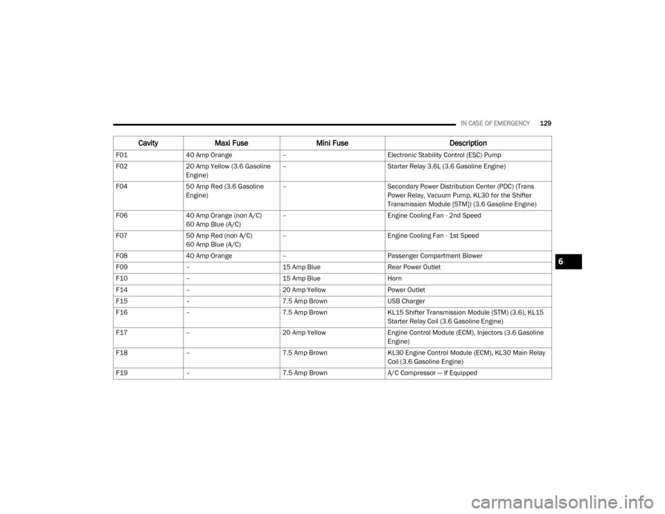
CavityMaxi Fuse Mini Fuse Description
F0140 Amp Orange – Electronic Stability Control (ESC) Pump
F02 20 Amp Yellow (3.6 Gasoline
Engine) –
Starter Relay 3.6L (3.6 Gasoline Engine)
F04 50 Amp Red (3.6 Gasoline
Engine) –
Secondary Power Distribution Center (PDC) (Trans
Power Relay, Vacuum Pump, KL30 for the Shifter
Transmission Module [STM]) (3.6 Gasoline Engine)
F06 40 Amp Orange (non A/C)
60 Amp Blue (A/C) –
Engine Cooling Fan - 2nd Speed
F07 50 Amp Red (non A/C)
60 Amp Blue (A/C) –
Engine Cooling Fan - 1st Speed
F08 40 Amp Orange – Passenger Compartment Blower
F09 – 15 Amp Blue Rear Power Outlet
F10 – 15 Amp Blue Horn
F14 – 20 Amp Yellow Power Outlet
F15 – 7.5 Amp Brown USB Charger
F16 – 7.5 Amp Brown KL15 Shifter Transmission Module (STM) (3.6), KL15
Starter Relay Coil (3.6 Gasoline Engine)
F17 – 20 Amp Yellow Engine Control Module (ECM), Injectors (3.6 Gasoline
Engine)
F18 – 7.5 Amp Brown KL30 Engine Control Module (ECM), KL30 Main Relay
Coil (3.6 Gasoline Engine)
F19 – 7.5 Amp Brown A/C Compressor — If Equipped
6
20_VF_OM_EN_US_t.book Page 129
Page 144 of 264
142IN CASE OF EMERGENCY
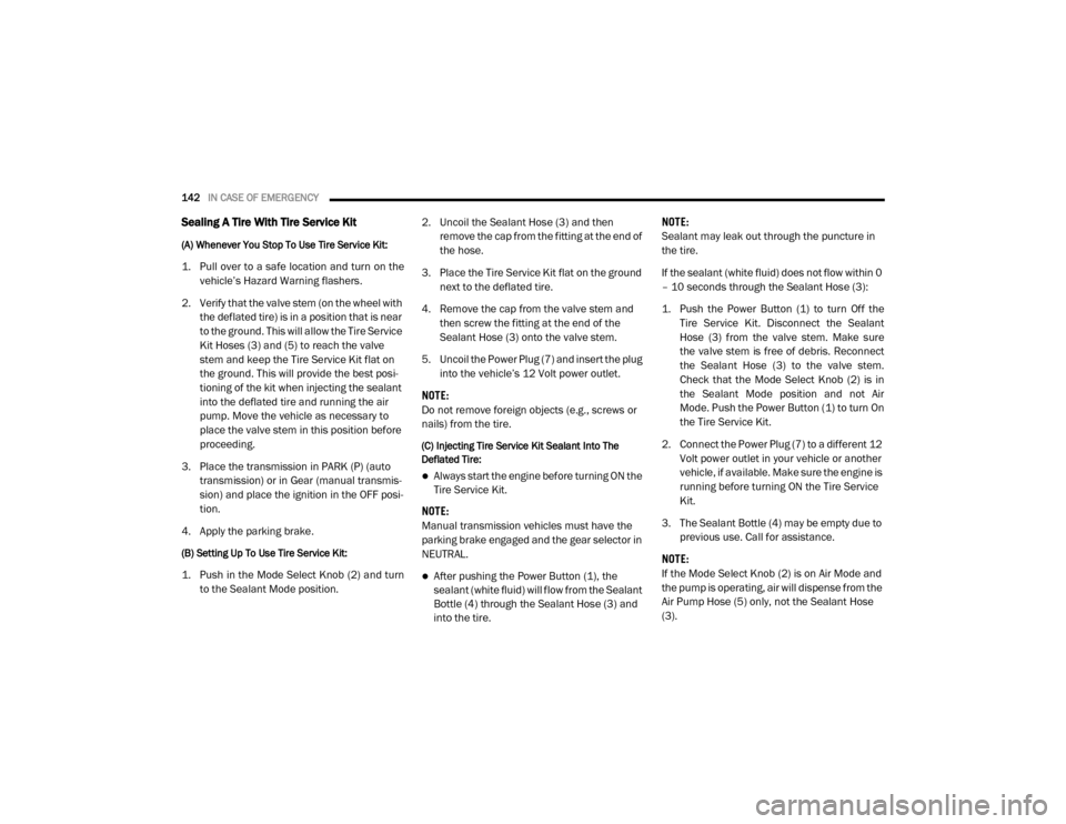
Sealing A Tire With Tire Service Kit
(A) Whenever You Stop To Use Tire Service Kit:
1. Pull over to a safe location and turn on the
vehicle’s Hazard Warning flashers.
2. Verify that the valve stem (on the wheel with the deflated tire) is in a position that is near
to the ground. This will allow the Tire Service
Kit Hoses (3) and (5) to reach the valve
stem and keep the Tire Service Kit flat on
the ground. This will provide the best posi -
tioning of the kit when injecting the sealant
into the deflated tire and running the air
pump. Move the vehicle as necessary to
place the valve stem in this position before
proceeding.
3. Place the transmission in PARK (P) (auto transmission) or in Gear (manual transmis -
sion) and place the ignition in the OFF posi -
tion.
4. Apply the parking brake.
(B) Setting Up To Use Tire Service Kit:
1. Push in the Mode Select Knob (2) and turn to the Sealant Mode position. 2. Uncoil the Sealant Hose (3) and then
remove the cap from the fitting at the end of
the hose.
3. Place the Tire Service Kit flat on the ground next to the deflated tire.
4. Remove the cap from the valve stem and then screw the fitting at the end of the
Sealant Hose (3) onto the valve stem.
5. Uncoil the Power Plug (7) and insert the plug into the vehicle’s 12 Volt power outlet.
NOTE:
Do not remove foreign objects (e.g., screws or
nails) from the tire.
(C) Injecting Tire Service Kit Sealant Into The
Deflated Tire:
Always start the engine before turning ON the
Tire Service Kit.
NOTE:
Manual transmission vehicles must have the
parking brake engaged and the gear selector in
NEUTRAL.
After pushing the Power Button (1), the
sealant (white fluid) will flow from the Sealant
Bottle (4) through the Sealant Hose (3) and
into the tire. NOTE:
Sealant may leak out through the puncture in
the tire.
If the sealant (white fluid) does not flow within 0
– 10 seconds through the Sealant Hose (3):
1. Push the Power Button (1) to turn Off the
Tire Service Kit. Disconnect the Sealant
Hose (3) from the valve stem. Make sure
the valve stem is free of debris. Reconnect
the Sealant Hose (3) to the valve stem.
Check that the Mode Select Knob (2) is in
the Sealant Mode position and not Air
Mode. Push the Power Button (1) to turn On
the Tire Service Kit.
2. Connect the Power Plug (7) to a different 12 Volt power outlet in your vehicle or another
vehicle, if available. Make sure the engine is
running before turning ON the Tire Service
Kit.
3. The Sealant Bottle (4) may be empty due to previous use. Call for assistance.
NOTE:
If the Mode Select Knob (2) is on Air Mode and
the pump is operating, air will dispense from the
Air Pump Hose (5) only, not the Sealant Hose
(3).
20_VF_OM_EN_US_t.book Page 142
Page 146 of 264
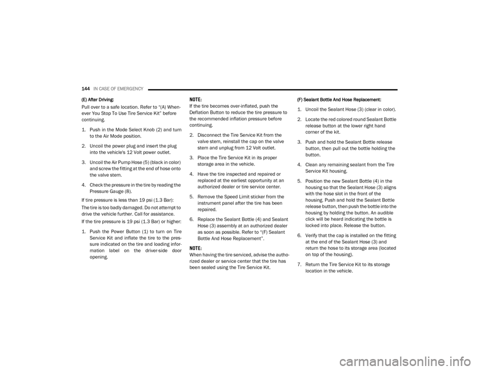
144IN CASE OF EMERGENCY
(E) After Driving:
Pull over to a safe location. Refer to “(A) When -
ever You Stop To Use Tire Service Kit” before
continuing.
1. Push in the Mode Select Knob (2) and turn to the Air Mode position.
2. Uncoil the power plug and insert the plug into the vehicle's 12 Volt power outlet.
3. Uncoil the Air Pump Hose (5) (black in color) and screw the fitting at the end of hose onto
the valve stem.
4. Check the pressure in the tire by reading the Pressure Gauge (8).
If tire pressure is less than 19 psi (1.3 Bar):
The tire is too badly damaged. Do not attempt to
drive the vehicle further. Call for assistance.
If the tire pressure is 19 psi (1.3 Bar) or higher:
1. Push the Power Button (1) to turn on Tire Service Kit and inflate the tire to the pres-
sure indicated on the tire and loading infor -
mation label on the driver-side door
opening. NOTE:
If the tire becomes over-inflated, push the
Deflation Button to reduce the tire pressure to
the recommended inflation pressure before
continuing.
2. Disconnect the Tire Service Kit from the
valve stem, reinstall the cap on the valve
stem and unplug from 12 Volt outlet.
3. Place the Tire Service Kit in its proper storage area in the vehicle.
4. Have the tire inspected and repaired or replaced at the earliest opportunity at an
authorized dealer or tire service center.
5. Remove the Speed Limit sticker from the instrument panel after the tire has been
repaired.
6. Replace the Sealant Bottle (4) and Sealant Hose (3) assembly at an authorized dealer
as soon as possible. Refer to “(F) Sealant
Bottle And Hose Replacement”.
NOTE:
When having the tire serviced, advise the autho -
rized dealer or service center that the tire has
been sealed using the Tire Service Kit.
(F) Sealant Bottle And Hose Replacement:
1. Uncoil the Sealant Hose (3) (clear in color).
2. Locate the red colored round Sealant Bottle release button at the lower right hand
corner of the kit.
3. Push and hold the Sealant Bottle release button, then pull out the bottle holding the
button.
4. Clean any remaining sealant from the Tire Service Kit housing.
5. Position the new Sealant Bottle (4) in the housing so that the Sealant Hose (3) aligns
with the hose slot in the front of the
housing. Push and hold the Sealant Bottle
release button, then push the bottle into the
housing by holding the button. An audible
click will be heard indicating the bottle is
locked into place. Release the button.
6. Verify that the cap is installed on the fitting at the end of the Sealant Hose (3) and
return the hose to its storage area (located
on top of the housing).
7. Return the Tire Service Kit to its storage location in the vehicle.
20_VF_OM_EN_US_t.book Page 144