service indicator Ram ProMaster 2020 Owner's Manual
[x] Cancel search | Manufacturer: RAM, Model Year: 2020, Model line: ProMaster, Model: Ram ProMaster 2020Pages: 264, PDF Size: 10.11 MB
Page 46 of 264
44GETTING TO KNOW YOUR INSTRUMENT PANEL
MODE Button
Push and hold the MODE button for a time
longer than one second to access/select the
information screens or submenu screens of a
main menu item. Push and hold the MODE
button for two seconds to reset displayed/
selected features that can be reset.
Up Arrow Button
Push and release the up arrow
button to scroll upward through the
main menu and submenus or
adjust the illumination on the
instrument panel when the headlights are on.
Down Arrow Button
Push and release the down arrow
button to scroll downward through
the main menu and submenus or
adjust the illumination on the
instrument panel when the headlights are on.
Change Engine Oil
Your vehicle is equipped with an engine oil
change indicator system. The “Change Engine
Oil” message will display in the instrument
cluster display. The engine oil change indicator
system is duty cycle based, which means the engine oil change interval may fluctuate, depen
-
dent upon your personal driving style.
Unless reset, this message will continue to
display each time you turn the ignition switch to
the ON/RUN position. To turn off the message
temporarily, push and release the MODE
button. To reset the oil change indicator system
(after performing the scheduled maintenance),
refer to the following procedure.
1. Turn the ignition switch to the ON position (do not start the engine).
2. Fully push the accelerator pedal slowly, three times, within 10 seconds.
3. Turn the ignition switch to the OFF/LOCK position.
NOTE:
If the indicator message illuminates when you
start the vehicle, the oil change indicator
system did not reset. If necessary, repeat this
procedure.Display Setup Menu
The menu comprises a series of functions
arranged in a cycle. Push and release the up or
down arrow button to access the different
options and settings (setup). The setup menu can be activated by pushing
the
MODE button. Single pushes on the up or
down arrow button will scroll through the setup
menu options. The menu items include the
following functions:
Speed Beep
Buzzer Volume
Seat Belt Buzzer (Just Available After SBR
Disable Made By CHR Service)
Exit menu
NOTE:
If equipped, some customer programmable
features will display in the Uconnect system.
Refer to your Uconnect Owner’s Manual Supple -
ment for further information.
Selecting An Option Of The Main Menu Without
Submenu
1. Briefly push and release the MODE button
to select the main menu option to set.
2. Push and release the up or down arrow
button (by single pushes) to select the new
setting.
20_VF_OM_EN_US_t.book Page 44
Page 49 of 264
GETTING TO KNOW YOUR INSTRUMENT PANEL47
“Trip B” can be used to display the figures
relating to:
Trip Distance B
Average Fuel Consumption
Average Speed B
Travel Time B (Driving Time)
NOTE:
“Trip B” functions may be excluded (see “Trip B
Data”). “Range” and “Instantaneous Fuel
Consumption” cannot be reset.
WARNING LIGHTS AND MESSAGES
The warning/indicator lights will illuminate in
the instrument panel together with a dedicated
message and/or acoustic signal when appli -
cable. These indications are indicative and
precautionary and as such must not be consid -
ered as exhaustive and/or alternative to the
information contained in the Owner’s Manual,
which you are advised to read carefully in all
cases. Always refer to the information in this
chapter in the event of a failure indication. All
active telltales will display first if applicable. The system check menu may appear different
based upon equipment options and current
vehicle status. Some telltales are optional and
may not appear.
Red Warning Lights
Seat Belt Reminder Warning Light
When the ignition is first placed in the
ON/RUN or MAR/ON/RUN position, if
the driver’s seat belt is unbuckled, a
chime will sound and the light will turn
on. When driving, if the driver or front passenger
seat belt remains unbuckled, the Seat Belt
Reminder Light will flash or remain on continu-
ously and a chime will sound. Refer to “Occu -
pant Restraints Systems” in “Safety” for further
information.
Air Bag Warning Light
This light will turn on for four to eight
seconds as a bulb check when the
ignition is placed in the ON/RUN or
MAR/ON/RUN position. If the light is
either not on during startup, stays on, or turns
on while driving, have the system inspected at
an authorized dealer as soon as possible. This
light will illuminate with a single chime when a fault with the Air Bag Warning Light has been
detected, it will stay on until the fault is cleared.
If the light comes on intermittently or remains
on while driving, have an authorized dealer
service the vehicle immediately.
Battery Charge Warning Light
This warning light will illuminate when
the battery is not charging properly. If
it stays on while the engine is running,
there may be a malfunction with the
charging system. Contact an authorized dealer
as soon as possible.
This indicates a possible problem with the elec -
trical system or a related component.
Door Open Warning Light
This indicator will illuminate when one
or more door(s) are not fully closed.
NOTE:
If the vehicle is moving and a door is opened,
there will also be a single chime.
3
20_VF_OM_EN_US_t.book Page 47
Page 50 of 264
48GETTING TO KNOW YOUR INSTRUMENT PANEL
Electronic Throttle Control (ETC) Warning Light
This warning light will illuminate to
inform of a problem with the Elec -
tronic Throttle Control (ETC) system. If
a problem is detected while the
vehicle is running, the light will either stay on or
flash depending on the nature of the problem.
Cycle the ignition when the vehicle is safely and
completely stopped and the transmission is
placed in the PARK (P) position. The light should
turn off. If the light remains on with the vehicle
running, your vehicle will usually be drivable;
however, see an authorized dealer for service
as soon as possible.
If the light continues to flash when the vehicle is
running, immediate service is required and you
may experience reduced performance, an
elevated/rough idle, or engine stall and your
vehicle may require towing. The light will come
on when the ignition is placed in the ON/RUN or
MAR/ON/RUN position and remain on briefly as
a bulb check. If the light does not come on
during starting, have the system checked by an
authorized dealer.
Transmission Fault Warning Light
This light will illuminate (together with
a message in the instrument cluster
display and a buzzer) to indicate a
transmission fault. Contact an autho -
rized dealer if the message remains after
restarting the engine.
Engine Temperature Warning Light
This light warns of an overheated
engine condition. If the engine
coolant temperature is too high, this
indicator will illuminate and a single
chime will sound.
If the light turns on while driving, safely pull over
and stop the vehicle. If the A/C system is on,
turn it off. Also, shift the transmission into
NEUTRAL and idle the vehicle. If the tempera -
ture reading does not return to normal, turn the
engine off immediately and call for service.
Refer to “If Your Engine Overheats” in “In Case
Of Emergency” for further information.
Brake Warning Light
This warning light monitors various
brake functions, including brake
fluid level and parking brake appli -
cation. If the brake light turns on it
may indicate that the parking brake is
applied, that the brake fluid level is low, or
that there is a problem with the anti-lock
brake system reservoir.
If the light remains on when the parking brake
has been disengaged, and the fluid level is at
the full mark on the master cylinder reservoir, it
indicates a possible brake hydraulic system
malfunction or that a problem with the Brake
Booster has been detected by the Anti-Lock
Brake System (ABS) / Electronic Stability
Control (ESC) system. In this case, the light will
remain on until the condition has been
corrected. If the problem is related to the brake
booster, the ABS pump will run when applying
the brake, and a brake pedal pulsation may be
felt during each stop.
20_VF_OM_EN_US_t.book Page 48
Page 54 of 264
52GETTING TO KNOW YOUR INSTRUMENT PANEL
Certain conditions, such as a loose or missing
gas cap, poor quality fuel, etc., may illuminate
the light after engine start. The vehicle should
be serviced if the light stays on through several
typical driving styles. In most situations, the
vehicle will drive normally and will not require
towing.
When the engine is running, the MIL may flash
to alert serious conditions that could lead to
immediate loss of power or severe catalytic
converter damage. The vehicle should be
serviced by an authorized dealer as soon as
possible if this occurs.
Anti-Lock Brake (ABS) Warning Light
This light monitors the Anti-Lock
Brake System (ABS). The light will turn
on when the ignition is placed in the
ON/RUN or MAR/ON/RUN position
and may stay on for as long as four seconds.
If the ABS light remains on or turns on while
driving, then the Anti-Lock portion of the brake
system is not functioning and service is
required. However, the conventional brake
system will continue to operate normally if the
brake warning light is not on.
If the ABS light is on, the brake system should
be serviced as soon as possible to restore the
benefits of Anti-Lock Brakes. If the ABS light
does not turn on when the ignition is placed in
the ON/RUN or MAR/ON/RUN position, have
the light inspected by an authorized dealer.
Generic Warning Light
The Generic Warning Light will illumi -
nate if any of the following conditions
occur: Engine Oil Pressure Sensor
Failure, External Light Failure, Fuel
Cut-Off intervention or fail, Parking Sensor
Failure, DST System Failure.
The telltale will remain on fixed in case of swivel
seat failure and on blinking in case of Air Bag
Warning Light Failure. Contact an authorized
dealer immediately for service.
Yellow Indicator Lights
Stop Light Failure Indicator Light
This light will illuminate if one or more
of the stop light bulb fails.
The failure relating to this light could be:
One or more blown bulbs.
A blown protection fuse.
A break in the electrical connection.
WARNING!
A malfunctioning catalytic converter, as
referenced above, can reach higher
temperatures than in normal operating
conditions. This can cause a fire if you drive
slowly or park over flammable substances
such as dry plants, wood, cardboard, etc. This
could result in death or serious injury to the
driver, occupants or others.
CAUTION!
Prolonged driving with the Malfunction
Indicator Light (MIL) on could cause damage
to the vehicle control system. It also could
affect fuel economy and driveability. If the
MIL is flashing, severe catalytic converter
damage and power loss will soon occur.
Immediate service is required.
20_VF_OM_EN_US_t.book Page 52
Page 56 of 264
54GETTING TO KNOW YOUR INSTRUMENT PANEL
ONBOARD DIAGNOSTIC SYSTEM — OBD II
Your vehicle is equipped with a sophisticated
Onboard Diagnostic system called OBD II. This
system monitors the performance of the emis -
sions, engine, and transmission control
systems. When these systems are operating
properly, your vehicle will provide excellent
performance and fuel economy, as well as
engine emissions well within current govern -
ment regulations.
If any of these systems require service, the OBD
II system will turn on the Malfunction Indicator
Light (MIL). It will also store diagnostic codes
and other information to assist your service
technician in making repairs. Although your
vehicle will usually be drivable and not need
towing, see an authorized dealer for service as
soon as possible.
Onboard Diagnostic System (OBD II)
Cybersecurity
Your vehicle is required to have an Onboard
Diagnostic system (OBD II) and a connection
port to allow access to information related to
the performance of your emissions controls.
Authorized service technicians may need to
access this information to assist with the diag -
nosis and service of your vehicle and emissions
system. For further information, refer to “Cybersecurity”
in “Multimedia”.
CAUTION!
Prolonged driving with the MIL on could
cause further damage to the emission
control system. It could also affect fuel
economy and driveability. The vehicle must
be serviced before any emissions tests can
be performed.
If the MIL is flashing while the vehicle is
running, severe catalytic converter damage
and power loss will soon occur. Immediate
service is required.
WARNING!
ONLY an authorized service technician
should connect equipment to the OBD II
connection port in order to read the VIN,
diagnose, or service your vehicle.
If unauthorized equipment is connected to
the OBD II connection port, such as a
driver-behavior tracking device, it may:
Be possible that vehicle systems,
including safety related systems, could
be impaired or a loss of vehicle control
could occur that may result in an acci-
dent involving serious injury or death.
Access, or allow others to access, infor- mation stored in your vehicle systems,
including personal information.
20_VF_OM_EN_US_t.book Page 54
Page 57 of 264
GETTING TO KNOW YOUR INSTRUMENT PANEL55
EMISSIONS INSPECTION AND
MAINTENANCE PROGRAMS
In some localities, it may be a legal requirement
to pass an inspection of your vehicle's emis-
sions control system. Failure to pass could
prevent vehicle registration.
For states that require an Inspection
and Maintenance (I/M), this check
verifies the “Malfunction Indicator
Light (MIL)” is functioning and is not
on when the engine is running, and that the
OBD II system is ready for testing.
Normally, the OBD II system will be ready. The
OBD II system may not be ready if your vehicle
was recently serviced, recently had a depleted
battery or a battery replacement. If the OBD II
system should be determined not ready for the
I/M test, your vehicle may fail the test. Your vehicle has a simple ignition actuated test,
which you can use prior to going to the test
station. To check if your vehicle's OBD II system
is ready, you must do the following:
1. Cycle the ignition switch to the ON position,
but do not crank or start the engine.
NOTE:
If you crank or start the engine, you will have to
start this test over.
2. As soon as you cycle the ignition switch to the ON position, you will see the “Malfunc -
tion Indicator Light (MIL)” symbol come on
as part of a normal bulb check.
3. Approximately 15 seconds later, one of two things will happen:
The MIL will flash for about 10 seconds
and then return to being fully illuminated
until you turn OFF the ignition or start the
engine. This means that your vehicle's
OBD II system is not ready and you should
not proceed to the I/M station.
The MIL will not flash at all and will remain
fully illuminated until you place the ignition
in the off position or start the engine. This
means that your vehicle's OBD II system is
ready and you can proceed to the I/M
station.
If your OBD II system is not ready, you should
see an authorized dealer or repair facility. If your
vehicle was recently serviced or had a battery
failure or replacement, you may need to do
nothing more than drive your vehicle as you
normally would in order for your OBD II system
to update. A recheck with the above test routine
may then indicate that the system is now ready.
Regardless of whether your vehicle's OBD II
system is ready or not, if the MIL is illuminated
during normal vehicle operation you should
have your vehicle serviced before going to the I/
M station. The I/M station can fail your vehicle
because the MIL is on with the engine running.
3
20_VF_OM_EN_US_t.book Page 55
Page 102 of 264
100STARTING AND OPERATING
Transmission Limp Home Mode
Transmission function is monitored electroni -
cally for abnormal conditions. If a condition is
detected that could result in transmission
damage, Transmission Limp Home Mode is acti -
vated. In this mode, the transmission remains
in third gear regardless of which forward gear is
selected. PARK, REVERSE, and NEUTRAL will
continue to operate. The Malfunction Indicator
Light (MIL) may be illuminated. Transmission
Limp Home Mode allows the vehicle to be
driven to an authorized dealer for service
without damaging the transmission. In the event of a momentary problem, the trans
-
mission can be reset to regain all forward gears
by performing the following steps:
1. Stop the vehicle.
2. Shift the transmission into PARK.
3. Turn the ignition OFF.
4. Wait approximately 10 seconds.
5. Restart the engine.
6. Shift into the desired gear range. If the problem is no longer detected, the trans -
mission will return to normal operation.
NOTE:
Even if the transmission can be reset, we
recommend that you visit your authorized
dealer at your earliest possible convenience.
Your authorized dealer has diagnostic equip -
ment to assess the condition of your transmis -
sion.
If the transmission cannot be reset, authorized
dealer service is required.
Electronic Range Select (ERS) Operation
The Electronic Range Select (ERS) shift control
allows the driver to limit the highest available
gear. For example, if you set the transmission
gear limit to 4 (fourth gear), the transmission
will not shift above fourth gear, but will shift
through the lower gears normally.
You can switch between DRIVE and ERS mode
at any vehicle speed. When the gear selector is
in the DRIVE position, the transmission will
operate automatically, shifting between all
available gears. Moving the gear selector to the
ERS position (beside DRIVE) will activate ERS
mode, display the current gear in the instru -
ment cluster, and set that gear as the top avail -
able gear. Once in ERS mode, moving the gear
selector forward (-) or rearward (+) will change
the top available gear.
To exit ERS mode, simply return the gear
selector to the DRIVE position.
WARNING!
Do not downshift for additional engine
braking on a slippery surface. The drive
wheels could lose their grip and the vehicle
could skid, causing a collision or personal
injury.
20_VF_OM_EN_US_t.book Page 100
Page 105 of 264
STARTING AND OPERATING103
Power Steering Fluid Check
Checking the power steering fluid level at a
defined service interval is not required. The fluid
should be checked at every oil change if a leak
is suspected, abnormal noises are apparent,
and/or the system is not functioning as antici -
pated. Coordinate inspection efforts through an
authorized dealer. If necessary, add fluid to restore to the proper
indicated level. With a clean cloth, wipe any
spilled fluid from all surfaces. Refer to “Fluids
And Lubricants” in “Technical Specifications”
for further information.
SPEED CONTROL — IF EQUIPPED
When engaged, the Speed Control takes over
accelerator operations at speeds greater than
25 mph (40 km/h) up to the maximum speed of
100 mph (160 km/h).
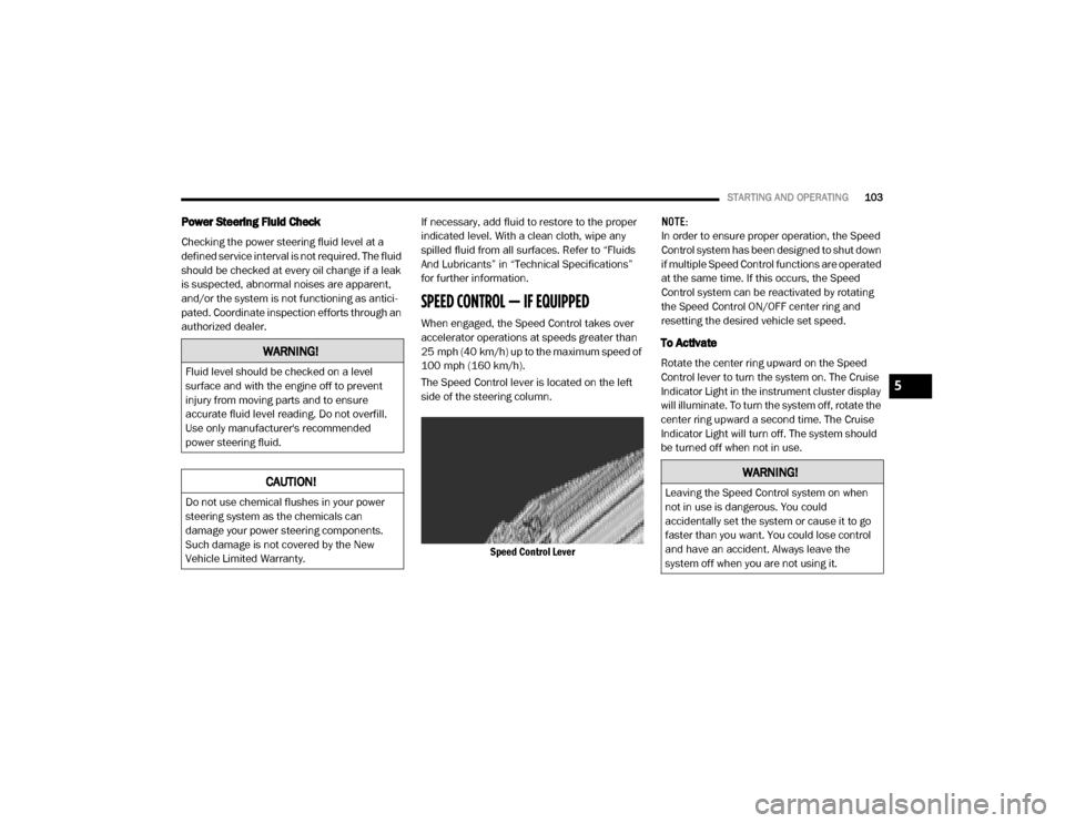
The Speed Control lever is located on the left
side of the steering column.
Speed Control Lever NOTE:
In order to ensure proper operation, the Speed
Control system has been designed to shut down
if multiple Speed Control functions are operated
at the same time. If this occurs, the Speed
Control system can be reactivated by rotating
the Speed Control ON/OFF center ring and
resetting the desired vehicle set speed.
To Activate
Rotate the center ring upward on the Speed
Control lever to turn the system on. The Cruise
Indicator Light in the instrument cluster display
will illuminate. To turn the system off, rotate the
center ring upward a second time. The Cruise
Indicator Light will turn off. The system should
be turned off when not in use.WARNING!
Fluid level should be checked on a level
surface and with the engine off to prevent
injury from moving parts and to ensure
accurate fluid level reading. Do not overfill.
Use only manufacturer's recommended
power steering fluid.
CAUTION!
Do not use chemical flushes in your power
steering system as the chemicals can
damage your power steering components.
Such damage is not covered by the New
Vehicle Limited Warranty.
WARNING!
Leaving the Speed Control system on when
not in use is dangerous. You could
accidentally set the system or cause it to go
faster than you want. You could lose control
and have an accident. Always leave the
system off when you are not using it.
5
20_VF_OM_EN_US_t.book Page 103
Page 154 of 264
152
SERVICING AND MAINTENANCE
SCHEDULED SERVICING
Your vehicle is equipped with an automatic oil
change indicator system. The oil change indi-
cator system will remind you that it is time to
take your vehicle in for scheduled maintenance.
Based on engine operation conditions, the oil
change indicator message will illuminate in the
instrument cluster. This means that service is
required for your vehicle. Operating conditions
such as frequent short-trips, trailer tow, and
extremely hot or cold ambient temperatures will
influence when the “Oil Change Required”
message is displayed. Severe Operating Condi-
tions can cause the change oil message to illu -
minate as early as 3,500 miles (5,600 km)
since last reset. Have the vehicle serviced as
soon as possible, within the next 500 miles
(805 km). An authorized dealer will reset the oil change
indicator message after completing the sched
-
uled oil change. If a scheduled oil change is
performed by someone other than an autho -
rized dealer, the message can be reset by refer -
ring to the steps described under “Instrument
Cluster Display” in “Getting To Know Your
Instrument Panel” for further information.
NOTE:
Under no circumstances should oil change
intervals exceed 10,000 miles (16,000 km),
12 months or 350 hours of engine run time,
whichever comes first. The 350 hours of engine
run or idle time is generally only a concern for
fleet customers.
Severe Duty All Models
Change Engine Oil at 4,000 miles (6,500 km) or
350 hours of engine run time if the vehicle is
operated in a dusty and off road environment or
is operated predominately at idle or only very
low engine RPM. This type of vehicle use is
considered Severe Duty. Once A Month Or Before A Long Trip:Check engine oil level
Check windshield washer fluid level
Check the tire inflation pressures and look
for unusual wear or damage. Rotate at the
first sign of irregular wear, even if it occurs
before the oil indicator system turns on
Check the fluid levels of the coolant reservoir,
brake master cylinder, and power steering
and fill as needed
Check function of all interior and exterior
lights
Maintenance Plan
Required Maintenance Intervals
Refer to the maintenance plan on the following
pages for the required maintenance intervals.
20_VF_OM_EN_US_t.book Page 152
Page 160 of 264
158SERVICING AND MAINTENANCE
Pressure Washing
DEALER SERVICE
An authorized dealer has the qualified service
personnel, special tools, and equipment to
perform all service operations in an expert
manner. Service Manuals are available which
include detailed service information for your
vehicle. Refer to these Service Manuals before
attempting any procedure yourself.
NOTE:
Intentional tampering with emissions control
systems may void your warranty and could
result in civil penalties being assessed against
you.
Engine Oil
Change Engine Oil
The oil change indicator system will remind you
that it is time to take your vehicle in for sched -
uled maintenance. Refer to the “Maintenance
Plan” for further information.
NOTE:
Under no circumstances should oil change
intervals exceed 10,000 miles (16,000 km),
12 months or 350 hours of engine run time,
whichever comes first. The 350 hours of engine
run or idle time is generally only a concern for
fleet customers.
Engine Oil Selection
For best performance and maximum protection
under all types of operating conditions, the
manufacturer only recommends engine oils
that are API Certified and meet the require -
ments of FCA Material Standard MS-6395.
CAUTION!
It is essential when replacing the cables on
the battery that the positive cable is
attached to the positive post and the nega -
tive cable is attached to the negative post.
Battery posts are marked positive (+) and
negative (-) and are identified on the battery
case. Cable clamps should be tight on the
terminal posts and free of corrosion.
If a “fast charger” is used while the battery
is in the vehicle, disconnect both vehicle
battery cables before connecting the
charger to the battery. Do not use a “fast
charger” to provide starting voltage.
CAUTION!
Cleaning the engine compartment with a high
pressure washer is not recommended.
Precautions have been taken to safeguard all
parts and connections however, the
pressures generated by these machines is
such that complete protection against water
ingress cannot be guaranteed.
WARNING!
You can be badly injured working on or
around a motor vehicle. Only do service work
for which you have the knowledge and the
proper equipment. If you have any doubt
about your ability to perform a service job,
take your vehicle to a competent mechanic.
20_VF_OM_EN_US_t.book Page 158