steering wheel Ram ProMaster 2020 Owner's Manual
[x] Cancel search | Manufacturer: RAM, Model Year: 2020, Model line: ProMaster, Model: Ram ProMaster 2020Pages: 264, PDF Size: 10.11 MB
Page 4 of 264

2
INTRODUCTION
INTRODUCTION ......................................................... 7
HOW TO USE THIS MANUAL ................................... 8
Essential Information ........................................... 8
Symbols ................................................................. 8
WARNINGS AND CAUTIONS ................................... 8
VAN CONVERSIONS/CAMPERS .............................. 8
VEHICLE MODIFICATIONS/ALTERATIONS ............. 8
GETTING TO KNOW YOUR VEHICLE
KEYS .......................................................................... 9
Key Fob ................................................................. 9
IGNITION SWITCH ................................................... 11
Mechanical Ignition Switch ................................ 11
Key-In-Ignition Reminder ................................... 12
SENTRY KEY............................................................. 12
Replacement Keys ............................................ 12
General Information ........................................... 12
VEHICLE SECURITY ALARM — IF EQUIPPED ....... 13
To Arm The System ............................................. 13
To Disarm The System ....................................... 13
Rearming Of The System ................................... 14
Security System Manual Override ..................... 14
DOORS ..................................................................... 14
Power Door Locks .............................................. 14
Auto Unlock Doors .............................................. 15
Automatic Door Locks ........................................ 15
SEATS .......................................................................15
Manual Adjustments .......................................... 15
Heated Seats — If Equipped .............................. 18
Fold Down Tray — If Equipped ........................... 19
Adjustable Armrests — If Equipped ................... 19
HEAD RESTRAINTS ................................................20
Front Head Restraint Adjustment ..................... 20
Front Head Restraint Removal .......................... 20
STEERING WHEEL ...................................................21
Telescoping Steering Column ............................ 21
MIRRORS .................................................................21
Inside Day/Night Mirror — If Equipped ............ 21
Outside Mirrors .................................................. 21
Power Mirrors — If Equipped ............................. 22
Power Folding Mirrors — If Equipped ................ 22
Heated Mirrors — If Equipped............................ 23
EXTERIOR LIGHTS ...................................................23
Multifunction Lever ........................................... 23
Headlights .......................................................... 23
Daytime Running Lights (DRLs) —
If Equipped ......................................................... 24 High Beam/Low Beam Select Switch .............. 24
Flash-To-Pass ..................................................... 24
Parking Lights .................................................... 24
Follow Me Home/Headlight Delay .................... 24
Fog Lights — If Equipped ................................... 25
Turn Signals ........................................................ 25
Lane Change Assist............................................ 25
Battery Saver ...................................................... 25
INTERIOR LIGHTS ................................................... 25
Courtesy Lights....................................................25
Illuminated Entry .................................................27
WIPERS AND WASHERS ........................................ 27
Front Wiper Operation .......................................27
CLIMATE CONTROLS .............................................. 28
Manual Climate Control Overview......................28
Climate Control Functions ..................................33
Operating Tips .....................................................33
WINDOWS ............................................................... 35
Power Windows ..................................................35
Window Bar Grates — If Equipped .....................36
Wind Buffeting ....................................................36
HOOD ........................................................................ 36
Opening ...............................................................36
Closing .................................................................37
CARGO AREA FEATURES ....................................... 37
INTERNAL EQUIPMENT .......................................... 37
Storage ................................................................37
Cupholders ..........................................................38
Power Outlets ......................................................39
Auxiliary Switches — If Equipped ........................40
20_VF_OM_EN_US_t.book Page 2
Page 5 of 264

3
GETTING TO KNOW YOUR INSTRUMENT
PANEL
INSTRUMENT CLUSTER .......................................... 41
Instrument Cluster Descriptions........................ 42
INSTRUMENT CLUSTER DISPLAY ......................... 43
Location And Controls ........................................ 43
Change Engine Oil .............................................. 44
Display Setup Menu ........................................... 44
Values Displayed ................................................ 45
Personal Settings (Customer-Programmable
Features) ............................................................. 46
TRIP COMPUTER ..................................................... 46
Trip Button .......................................................... 46
Trip Functions ..................................................... 46
WARNING LIGHTS AND MESSAGES ..................... 47
Red Warning Lights ............................................ 47
Yellow Warning Lights ........................................ 50
Yellow Indicator Lights ....................................... 52
Green Indicator Lights ........................................ 53
Blue Indicator Lights .......................................... 53
ONBOARD DIAGNOSTIC SYSTEM — OBD II ........ 54
Onboard Diagnostic System (OBD II)
Cybersecurity ...................................................... 54
EMISSIONS INSPECTION AND MAINTENANCE
PROGRAMS ............................................................. 55
SAFETY
SAFETY FEATURES ..................................................56
Four-Wheel Anti-Lock Brake System (ABS) ....... 56
Electronic Brake Control (EBC) System ........... 57
AUXILIARY DRIVING SYSTEMS ..............................61
Tire Pressure Monitoring System (TPMS) ......... 61
OCCUPANT RESTRAINT SYSTEMS .......................64
Occupant Restraint Systems Features ............ 64
Important Safety Precautions............................ 65
Seat Belt Systems ............................................. 66
Supplemental Restraint Systems (SRS) ........... 73
Child Restraints .................................................. 83
Transporting Pets .............................................. 89
SAFETY TIPS ............................................................89
Transporting Passengers ................................... 89
Exhaust Gas ........................................................ 89
Safety Checks You Should Make Inside
The Vehicle ........................................................ 90 Periodic Safety Checks You Should Make
Outside The Vehicle ........................................... 91
STARTING AND OPERATING
STARTING THE ENGINE ..........................................92
Automatic Transmission .................................... 92
Normal Starting .................................................. 92
Cold Weather Operation
(Below –22°F Or −30°C) ................................. 92 If Engine Fails To Start ....................................... 92
After Starting ...................................................... 93
ENGINE BLOCK HEATER — IF EQUIPPED ............ 93
ENGINE BREAK-IN RECOMMENDATIONS ........... 93
PARKING BRAKE ................................................... 94
AUTOMATIC TRANSMISSION ................................ 95
Key Ignition Park Interlock .................................96
Brake/Transmission Shift Interlock System ....96
Six-Speed Automatic Transmission ...................96
POWER STEERING ............................................... 102
Power Steering Fluid Check ........................... 103
SPEED CONTROL — IF EQUIPPED ......................103
To Activate ........................................................ 103
To Set A Desired Speed ................................... 104
To Vary The Speed Setting .............................. 104
To Accelerate For Passing ............................... 105
To Resume Speed ............................................ 105
To Deactivate ................................................... 105
PARKSENSE REAR PARK ASSIST —
IF EQUIPPED ..........................................................105
ParkSense Rear Park Assist Sensors ............. 106
ParkSense Rear Park Assist Alerts ................. 106
ParkSense Rear Park Assist Failure
Indications ........................................................ 108 Cleaning The ParkSense System .................... 108
ParkSense Rear Park Assist System Usage
Precautions ...................................................... 108
PARKVIEW REAR BACK UP CAMERA ............... 109
REFUELING THE VEHICLE.....................................111
Loose Fuel Filler Cap Message ....................... 111
20_VF_OM_EN_US_t.book Page 3
Page 7 of 264

5
TIRES .....................................................................168
Tire Safety Information ....................................168
Tires — General Information ........................... 176
Tire Types .......................................................... 180
Spare Tires — If Equipped ............................... 181
Wheel And Wheel Trim Care ........................... 183
Tire Chains And Traction Devices ................... 184
Tire Rotation Recommendations..................... 185
DEPARTMENT OF TRANSPORTATION
UNIFORM TIRE QUALITY GRADES .....................185
Treadwear .........................................................186
Traction Grades ................................................ 186
Temperature Grades ........................................186
STORING THE VEHICLE ........................................186
BODYWORK ...........................................................187
Protection From Atmospheric Agents.............. 187
Body And Underbody Maintenance ................. 187
Preserving The Bodywork................................. 187
INTERIORS ............................................................188
Seats And Fabric Parts ..................................... 188
Plastic And Coated Parts..................................189
Leather Parts .................................................... 190Glass Surfaces ................................................. 190
Cleaning The Instrument Panel Cupholders ...190
TECHNICAL SPECIFICATIONS
IDENTIFICATION DATA ......................................... 191
Vehicle Identification Number ........................ 191
BRAKE SYSTEM .................................................... 191
WHEEL AND TIRE TORQUE SPECIFICATIONS ... 191
Torque Specifications ...................................... 191
FUEL REQUIREMENTS.......................................... 192
3.6L Engine....................................................... 192
Reformulated Gasoline ................................... 192
Materials Added To Fuel .................................. 193
Gasoline/Oxygenate Blends ............................ 193
Do Not Use E-85 In Non-Flex Fuel Vehicles .... 193
CNG And LP Fuel System Modifications ......... 193
MMT In Gasoline .............................................. 194Fuel System Cautions ...................................... 194
Carbon Monoxide Warnings ............................ 194
FLUID CAPACITIES................................................ 195
FLUIDS AND LUBRICANTS .................................. 195
Engine ............................................................... 195Chassis ............................................................. 197
MULTIMEDIA
CYBERSECURITY .................................................. 198
UCONNECT SETTINGS ......................................... 199
Uconnect 3/3 NAV Settings............................. 199
SAFETY AND GENERAL INFORMATION ............. 208
Safety Guidelines ............................................. 208
UCONNECT 3/3 NAV WITH 5-INCH DISPLAY ....209
Introduction To The Uconnect 3/3 NAV
With 5-Inch Display System ............................. 209 Radio Mode ...................................................... 211
Media Mode ..................................................... 214
Phone Mode ..................................................... 216
Navigation Mode — If Equipped ...................... 221
STEERING WHEEL AUDIO CONTROLS ............... 238
Radio Operation ............................................... 238
Player Operation............................................... 238
IPOD®/USB/MP3 CONTROL —
IF EQUIPPED ......................................................... 238
USB Charging Port............................................ 239
RAM TELEMATICS - IF EQUIPPED ....................... 239
Ram Telematics General Information............. 239
RADIO OPERATION AND MOBILE PHONES ......240
Regulatory And Safety Information ................. 240
UCONNECT VOICE RECOGNITION ......................241
Introducing Uconnect....................................... 241
Get Started ....................................................... 241
Basic Voice Commands ................................... 242
Radio ................................................................. 242
Media ................................................................ 243
Phone................................................................ 243
Voice Text Reply ............................................... 244
General Information......................................... 245
Additional Information ..................................... 245
20_VF_OM_EN_US_t.book Page 5
Page 23 of 264
GETTING TO KNOW YOUR VEHICLE21
STEERING WHEEL
Telescoping Steering Column
This feature allows you to lengthen or shorten
the steering column. The telescoping control
handle is located below the steering wheel at
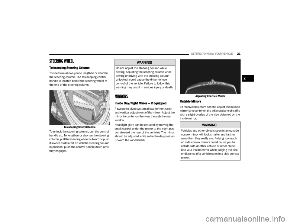
the end of the steering column.
Telescoping Control Handle
To unlock the steering column, pull the control
handle up. To lengthen or shorten the steering
column, pull the steering wheel outward or push
it inward as desired. To lock the steering column
in position, push the control handle down until
fully engaged.
MIRRORS
Inside Day/Night Mirror — If Equipped
A two-point pivot system allows for horizontal
and vertical adjustment of the mirror. Adjust the
mirror to center on the view through the rear
window.
Headlight glare can be reduced by moving the
small control under the mirror to the night posi -
tion (toward the rear of the vehicle). The mirror
should be adjusted while set in the day position
(toward the windshield). Adjusting Rearview Mirror
Outside Mirrors
To receive maximum benefit, adjust the outside
mirror(s) to center on the adjacent lane of traffic
with a slight overlap of the view obtained on the
inside mirror.
WARNING!
Do not adjust the steering column while
driving. Adjusting the steering column while
driving or driving with the steering column
unlocked, could cause the driver to lose
control of the vehicle. Failure to follow this
warning may result in serious injury or death.
WARNING!
Vehicles and other objects seen in an outside
convex mirror will look smaller and farther
away than they really are. Relying too much
on side convex mirrors could cause you to
collide with another vehicle or other object.
Use your inside mirror when judging the size
or distance of a vehicle seen in a side convex
mirror.
2
20_VF_OM_EN_US_t.book Page 21
Page 26 of 264

24GETTING TO KNOW YOUR VEHICLE
Daytime Running Lights (DRLs) — If
Equipped
NOTE:
When the headlights are turned on, the Daytime
Running Lights will be deactivated.
To activate the Daytime Running Lights (DRLs),
rotate the end of the multifunction lever to the
O (off) position.
NOTE:
The low beams and side/taillights will not be
on with DRLs.
In certain markets, the DRLs may be optional
and can be programmed to be on or off
through the Uconnect system screen. Refer
to “Uconnect Settings” in “Multimedia” for
further information.
The Daytime Running Lights will come on when -
ever the ignition is ON, the headlight switch is
off, and the turn signal is off.
High Beam/Low Beam Select Switch
With the low beams activated, pull the multi -
function lever toward the steering wheel to
switch the headlights to high beam. A high
beam symbol will be illuminated in the cluster to
indicate the high beams are on. Pull the lever a
second time to switch the headlights back to
low beam.
NOTE:
If the vehicle’s ignition is placed in the STOP
(OFF/LOCK) position, both high and low beam
headlights will also be turned off.
Flash-To-Pass
You can signal another vehicle with your head -
lights by partially pulling the multifunction lever
toward the steering wheel. This will cause the
high beam headlights to turn on until the lever
is released.
Parking Lights
These lights can only be turned on with ignition
key in the STOP (OFF/LOCK) position or
removed, by moving the end of the multifunc -
tion lever to O (off) position and then to the
headlight position. The warning light telltale in the instrument
panel comes on. The lights stay on until the next
ignition cycle is performed.
Follow Me Home/Headlight Delay
When this feature is selected, the driver can
choose to have the headlights remain on for a
preset period of time.
Activation
Remove the key or turn the ignition to the STOP
(OFF/LOCK) position, and pull the multifunction
lever toward the steering wheel, within two
minutes. Each time the lever is pulled, the acti
-
vation of the lights will be extended by 30
seconds. The activation of the lights can be
extended to a maximum of 210 seconds.
The warning light on the instrument panel will
light up and the corresponding message will
appear in the instrument cluster display for as
long as the function is activated. The warning
light comes on when the lever is operated and
stays on until the function is automatically deac -
tivated. Each movement of the lever only
increases the amount of time the lights stay on.
Deactivation
Pull the multifunction lever toward the steering
wheel and hold it for more than two seconds.
20_VF_OM_EN_US_t.book Page 24
Page 30 of 264
28GETTING TO KNOW YOUR VEHICLE
Intermittent Wiper System
Push the lever downward to the first detent and
rotate the center ring to use one of the four
intermittent wiper settings when weather condi -
tions make a single wiping cycle, with a variable
delay between cycles, desirable.
Low Speed
Push the lever downward to the second detent.
The wipers will operate at low speed.
High Speed
Push the lever downward to the third detent.
The wipers will operate at high speed.
Windshield Washer Operation
To use the washer, pull the windshield wiper/
washer lever toward the steering wheel to acti -
vate. The wipers will activate automatically for
three cycles after the lever is released, and then
resume the intermittent interval previously
selected.
If the lever is pulled while in the off position, the
wipers will operate for three cycles and then
turn off.
Mist Feature
Use the Mist feature when weather conditions
make occasional usage of the wipers neces -
sary. Push the lever upward to the MIST position
and release for a single wiping cycle.
NOTE:
The mist feature does not activate the washer
pump; therefore, no washer fluid will be sprayed
on the windshield. The wash function must be
used in order to spray the windshield with
washer fluid.
CLIMATE CONTROLS
The Climate Control System allows you to regu -
late the temperature, air flow, and direction of
air circulating throughout the vehicle. The
controls are located on the touchscreen (if
equipped) and on the instrument panel below
the radio.
Manual Climate Control Overview
The Manual Temperature Controls consist of a
series of three outer rotary dials (blower speed,
temperature and mode) and three inner push
buttons (Recirculation, A/C, Rear Window
Defroster).
Manual Temperature Controls
WARNING!
Sudden loss of visibility through the
windshield could lead to a collision. You might
not see other vehicles or other obstacles. To
avoid sudden icing of the windshield during
freezing weather, warm the windshield with
the defroster before and during windshield
washer use.
20_VF_OM_EN_US_t.book Page 28
Page 45 of 264
GETTING TO KNOW YOUR INSTRUMENT PANEL43
5. Fuel Gauge
The pointer shows the level of fuel in the
fuel tank when the ignition switch is in
the ON/RUN position.
The fuel pump symbol points to the
side of the vehicle where the fuel door is
located.
INSTRUMENT CLUSTER DISPLAY
Your vehicle will be equipped with an instru -
ment cluster display, which offers useful infor -
mation to the driver. With the ignition in the
STOP (OFF/LOCK) mode, opening/closing of a
door will activate the display for viewing, and
display the total miles, or kilometers, in the
odometer. Your instrument cluster display is
designed to display important information
about your vehicle’s systems and features.
Using a driver interactive display located on the
instrument panel, your instrument cluster
display can show you how systems are working
and give you warnings when they are not. The
steering wheel mounted controls allow you to
scroll through the main menus and submenus.
You can access the specific information you
want and make selections and adjustments.
Location And Controls
The instrument cluster display features a driver
interactive display that is located in the instru -
ment cluster.
Instrument Cluster Display
This system allows the driver to select a variety
of useful information by pushing the switches
mounted on the instrument panel. Examples of
menu items are:
Speed Beep
Buzzer Volume
Seat Belt Buzzer (Just Available After SBR
Disable Made By CHR Service)
Exit Menu If equipped with a Uconnect system, some
customer programmable features will display in
the radio. Refer to the “Uconnect Settings” in
“Multimedia” for further information.
The system allows the driver to select informa
-
tion by pushing the following buttons mounted
on the instrument panel to the left of the
steering column:
Display Control Buttons
NOTE:
The MODE button must be pushed prior to
pressing the up arrow and down arrow buttons.
3
20_VF_OM_EN_US_t.book Page 43
Page 58 of 264
56
(Continued)
SAFETY
SAFETY FEATURES
Four-Wheel Anti-Lock Brake System (ABS)
The Four-Wheel Anti-Lock Brake System (ABS) is
designed to aid the driver in maintaining vehicle
control under adverse braking conditions. The
system operates with a separate computer to
modulate hydraulic pressure, to prevent wheel
lock-up and to help avoid skidding on slippery
surfaces.
The system's pump motor runs during an ABS
stop to provide regulated hydraulic pressure.
The pump motor makes a low humming noise
during operation, which is normal.
The ABS includes an amber ABS Warning
Light. When the light is illuminated, the ABS is
not functioning. The system reverts to stan-
dard non-anti-lock brakes. Placing the ignition
in the OFF mode and to the ON mode again
may reset the ABS if the fault detected was
only momentary. When you are in a severe braking condition
involving the use of the ABS, you will experience
some pedal drop as the vehicle comes to a stop.
This is the result of the system reverting to the
base brake system.
Engagement of the ABS may be accompanied
by a pulsing sensation. You may also hear a
clicking noise. These occurrences are normal
and indicate that the system is functioning
properly.
WARNING!
The ABS contains sophisticated electronic
equipment that may be susceptible to inter
-
ference caused by improperly installed or
high output radio transmitting equipment.
This interference can cause possible loss of
anti-lock braking capability. Installation of
such equipment should be performed by
qualified professionals.
Pumping of the Anti-Lock Brakes will
diminish their effectiveness and may lead
to a collision. Pumping makes the stopping
distance longer. Just press firmly on your
brake pedal when you need to slow down or
stop.
The ABS cannot prevent the natural laws of
physics from acting on the vehicle, nor can
it increase braking or steering efficiency
beyond that afforded by the condition of the
vehicle brakes and tires or the traction
afforded.
The ABS cannot prevent collisions,
including those resulting from excessive
speed in turns, following another vehicle
too closely, or hydroplaning.
The capabilities of an ABS equipped vehicle
must never be exploited in a reckless or
dangerous manner that could jeopardize
the user’s safety or the safety of others.
WARNING!
(Continued)
20_VF_OM_EN_US_t.book Page 56
Page 59 of 264
SAFETY57
Electronic Brake Control (EBC) System
Your vehicle is equipped with an advanced Elec -
tronic Brake Control (EBC) system that includes
the Traction Control System (TCS), Brake Assist
System (BAS) and Electronic Stability Control
(ESC), Trailer Sway Control (TSC), and Hill Start
Assist (HSA). These systems complement the
Anti-Lock Brake System (ABS) by optimizing the
vehicle braking capability during emergency
braking maneuvers.
Brake Assist System (BAS)
The Brake Assist Sys tem (BAS) is designed to
optimize the vehicle’s braking c apability
during e merg ency braking maneuvers. The
system detects an emergency braking situa -
tio n by sensing the rate and am ount of brake
applic ation and then applies optimum pres -
sure to the brakes. This can help reduce
braking distance s. The BAS complements
the Anti-Lock Brake System (ABS). Applying
the brakes very quickly res ults in the best
BAS assistance . To rec eive the be ne fit of the
system , yo u must apply continuous braking pressure during the stopping sequence (do
not “pum p” the brakes). Do not reduce brake
pedal pre ssure unless braking is no longer
desired. Onc e the brake pedal is released,
the BAS is deac tivated.
Electronic Stability Control (ESC)
The Electronic Stability Control (ESC) enhances
directional control and stability of the vehicle
under various driving conditions. ESC corrects
for over/under steering of the vehicle by
applying the brake of the appropriate wheel to
assist in counteracting the over/under steer
condition. Engine power may also be reduced to
help the vehicle maintain the desired path.
ESC uses sensors in the vehicle to determine
the vehicle path intended by the driver and
compares it to the actual path of the vehicle.
When the actual path does not match the
intended path, ESC applies the brake of the
appropriate wheel to assist in counteracting the
oversteer or understeer condition.
Oversteer - when the vehicle is turning more
than appropriate for the steering wheel posi
-
tion.
Understeer - when the vehicle is turning
less than appropriate for the steering
wheel position.
WARNING!
The Brake Assist System (BAS) cannot
prevent the natural laws of physics from
acting on the vehicle, nor can it increase the
traction afforded by prevailing road
conditions. BAS cannot prevent collisions,
including those resulting from excessive
speed in turns, driving on very slippery
surfaces, or hydroplaning. The capabilities of
a BAS-equipped vehicle must never be
exploited in a reckless or dangerous manner,
which could jeopardize the user's safety or
the safety of others.
4
20_VF_OM_EN_US_t.book Page 57
Page 60 of 264
58SAFETY
(Continued)
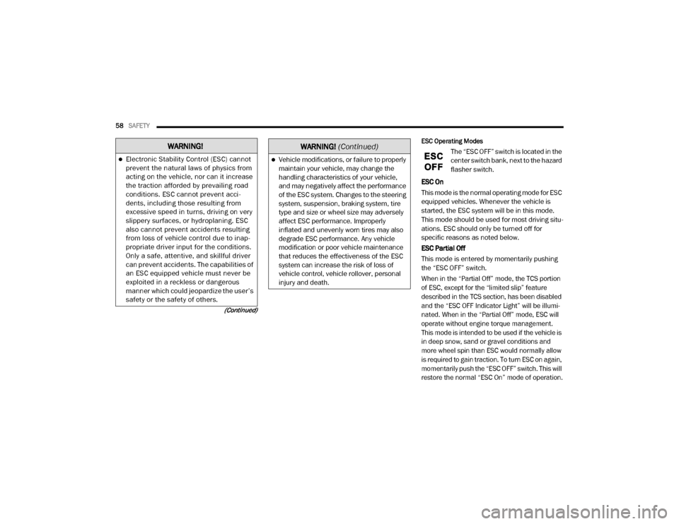
ESC Operating Modes
The “ESC OFF” switch is located in the
center switch bank, next to the hazard
flasher switch.
ESC On
This mode is the normal operating mode for ESC
equipped vehicles. Whenever the vehicle is
started, the ESC system will be in this mode.
This mode should be used for most driving situ -
ations. ESC should only be turned off for
specific reasons as noted below.
ESC Partial Off
This mode is entered by momentarily pushing
the “ESC OFF” switch.
When in the “Partial Off” mode, the TCS portion
of ESC, except for the “limited slip” feature
described in the TCS section, has been disabled
and the “ESC OFF Indicator Light” will be illumi-
nated. When in the “Partial Off” mode, ESC will
operate without engine torque management.
This mode is intended to be used if the vehicle is
in deep snow, sand or gravel conditions and
more wheel spin than ESC would normally allow
is required to gain traction. To turn ESC on again,
momentarily push the “ESC OFF” switch. This will
restore the normal “ESC On” mode of operation.
WARNING!
Electronic Stability Control (ESC) cannot
prevent the natural laws of physics from
acting on the vehicle, nor can it increase
the traction afforded by prevailing road
conditions. ESC cannot prevent acci -
dents, including those resulting from
excessive speed in turns, driving on very
slippery surfaces, or hydroplaning. ESC
also cannot prevent accidents resulting
from loss of vehicle control due to inap -
propriate driver input for the conditions.
Only a safe, attentive, and skillful driver
can prevent accidents. The capabilities of
an ESC equipped vehicle must never be
exploited in a reckless or dangerous
manner which could jeopardize the user’s
safety or the safety of others.Vehicle modifications, or failure to properly
maintain your vehicle, may change the
handling characteristics of your vehicle,
and may negatively affect the performance
of the ESC system. Changes to the steering
system, suspension, braking system, tire
type and size or wheel size may adversely
affect ESC performance. Improperly
inflated and unevenly worn tires may also
degrade ESC performance. Any vehicle
modification or poor vehicle maintenance
that reduces the effectiveness of the ESC
system can increase the risk of loss of
vehicle control, vehicle rollover, personal
injury and death.
WARNING!
(Continued)
20_VF_OM_EN_US_t.book Page 58