display Ram ProMaster 2020 Owner's Manual
[x] Cancel search | Manufacturer: RAM, Model Year: 2020, Model line: ProMaster, Model: Ram ProMaster 2020Pages: 264, PDF Size: 10.11 MB
Page 5 of 264

3
GETTING TO KNOW YOUR INSTRUMENT
PANEL
INSTRUMENT CLUSTER .......................................... 41
Instrument Cluster Descriptions........................ 42
INSTRUMENT CLUSTER DISPLAY ......................... 43
Location And Controls ........................................ 43
Change Engine Oil .............................................. 44
Display Setup Menu ........................................... 44
Values Displayed ................................................ 45
Personal Settings (Customer-Programmable
Features) ............................................................. 46
TRIP COMPUTER ..................................................... 46
Trip Button .......................................................... 46
Trip Functions ..................................................... 46
WARNING LIGHTS AND MESSAGES ..................... 47
Red Warning Lights ............................................ 47
Yellow Warning Lights ........................................ 50
Yellow Indicator Lights ....................................... 52
Green Indicator Lights ........................................ 53
Blue Indicator Lights .......................................... 53
ONBOARD DIAGNOSTIC SYSTEM — OBD II ........ 54
Onboard Diagnostic System (OBD II)
Cybersecurity ...................................................... 54
EMISSIONS INSPECTION AND MAINTENANCE
PROGRAMS ............................................................. 55
SAFETY
SAFETY FEATURES ..................................................56
Four-Wheel Anti-Lock Brake System (ABS) ....... 56
Electronic Brake Control (EBC) System ........... 57
AUXILIARY DRIVING SYSTEMS ..............................61
Tire Pressure Monitoring System (TPMS) ......... 61
OCCUPANT RESTRAINT SYSTEMS .......................64
Occupant Restraint Systems Features ............ 64
Important Safety Precautions............................ 65
Seat Belt Systems ............................................. 66
Supplemental Restraint Systems (SRS) ........... 73
Child Restraints .................................................. 83
Transporting Pets .............................................. 89
SAFETY TIPS ............................................................89
Transporting Passengers ................................... 89
Exhaust Gas ........................................................ 89
Safety Checks You Should Make Inside
The Vehicle ........................................................ 90 Periodic Safety Checks You Should Make
Outside The Vehicle ........................................... 91
STARTING AND OPERATING
STARTING THE ENGINE ..........................................92
Automatic Transmission .................................... 92
Normal Starting .................................................. 92
Cold Weather Operation
(Below –22°F Or −30°C) ................................. 92 If Engine Fails To Start ....................................... 92
After Starting ...................................................... 93
ENGINE BLOCK HEATER — IF EQUIPPED ............ 93
ENGINE BREAK-IN RECOMMENDATIONS ........... 93
PARKING BRAKE ................................................... 94
AUTOMATIC TRANSMISSION ................................ 95
Key Ignition Park Interlock .................................96
Brake/Transmission Shift Interlock System ....96
Six-Speed Automatic Transmission ...................96
POWER STEERING ............................................... 102
Power Steering Fluid Check ........................... 103
SPEED CONTROL — IF EQUIPPED ......................103
To Activate ........................................................ 103
To Set A Desired Speed ................................... 104
To Vary The Speed Setting .............................. 104
To Accelerate For Passing ............................... 105
To Resume Speed ............................................ 105
To Deactivate ................................................... 105
PARKSENSE REAR PARK ASSIST —
IF EQUIPPED ..........................................................105
ParkSense Rear Park Assist Sensors ............. 106
ParkSense Rear Park Assist Alerts ................. 106
ParkSense Rear Park Assist Failure
Indications ........................................................ 108 Cleaning The ParkSense System .................... 108
ParkSense Rear Park Assist System Usage
Precautions ...................................................... 108
PARKVIEW REAR BACK UP CAMERA ............... 109
REFUELING THE VEHICLE.....................................111
Loose Fuel Filler Cap Message ....................... 111
20_VF_OM_EN_US_t.book Page 3
Page 7 of 264

5
TIRES .....................................................................168
Tire Safety Information ....................................168
Tires — General Information ........................... 176
Tire Types .......................................................... 180
Spare Tires — If Equipped ............................... 181
Wheel And Wheel Trim Care ........................... 183
Tire Chains And Traction Devices ................... 184
Tire Rotation Recommendations..................... 185
DEPARTMENT OF TRANSPORTATION
UNIFORM TIRE QUALITY GRADES .....................185
Treadwear .........................................................186
Traction Grades ................................................ 186
Temperature Grades ........................................186
STORING THE VEHICLE ........................................186
BODYWORK ...........................................................187
Protection From Atmospheric Agents.............. 187
Body And Underbody Maintenance ................. 187
Preserving The Bodywork................................. 187
INTERIORS ............................................................188
Seats And Fabric Parts ..................................... 188
Plastic And Coated Parts..................................189
Leather Parts .................................................... 190Glass Surfaces ................................................. 190
Cleaning The Instrument Panel Cupholders ...190
TECHNICAL SPECIFICATIONS
IDENTIFICATION DATA ......................................... 191
Vehicle Identification Number ........................ 191
BRAKE SYSTEM .................................................... 191
WHEEL AND TIRE TORQUE SPECIFICATIONS ... 191
Torque Specifications ...................................... 191
FUEL REQUIREMENTS.......................................... 192
3.6L Engine....................................................... 192
Reformulated Gasoline ................................... 192
Materials Added To Fuel .................................. 193
Gasoline/Oxygenate Blends ............................ 193
Do Not Use E-85 In Non-Flex Fuel Vehicles .... 193
CNG And LP Fuel System Modifications ......... 193
MMT In Gasoline .............................................. 194Fuel System Cautions ...................................... 194
Carbon Monoxide Warnings ............................ 194
FLUID CAPACITIES................................................ 195
FLUIDS AND LUBRICANTS .................................. 195
Engine ............................................................... 195Chassis ............................................................. 197
MULTIMEDIA
CYBERSECURITY .................................................. 198
UCONNECT SETTINGS ......................................... 199
Uconnect 3/3 NAV Settings............................. 199
SAFETY AND GENERAL INFORMATION ............. 208
Safety Guidelines ............................................. 208
UCONNECT 3/3 NAV WITH 5-INCH DISPLAY ....209
Introduction To The Uconnect 3/3 NAV
With 5-Inch Display System ............................. 209 Radio Mode ...................................................... 211
Media Mode ..................................................... 214
Phone Mode ..................................................... 216
Navigation Mode — If Equipped ...................... 221
STEERING WHEEL AUDIO CONTROLS ............... 238
Radio Operation ............................................... 238
Player Operation............................................... 238
IPOD®/USB/MP3 CONTROL —
IF EQUIPPED ......................................................... 238
USB Charging Port............................................ 239
RAM TELEMATICS - IF EQUIPPED ....................... 239
Ram Telematics General Information............. 239
RADIO OPERATION AND MOBILE PHONES ......240
Regulatory And Safety Information ................. 240
UCONNECT VOICE RECOGNITION ......................241
Introducing Uconnect....................................... 241
Get Started ....................................................... 241
Basic Voice Commands ................................... 242
Radio ................................................................. 242
Media ................................................................ 243
Phone................................................................ 243
Voice Text Reply ............................................... 244
General Information......................................... 245
Additional Information ..................................... 245
20_VF_OM_EN_US_t.book Page 5
Page 20 of 264
18GETTING TO KNOW YOUR VEHICLE
Swivel Seat — If Equipped
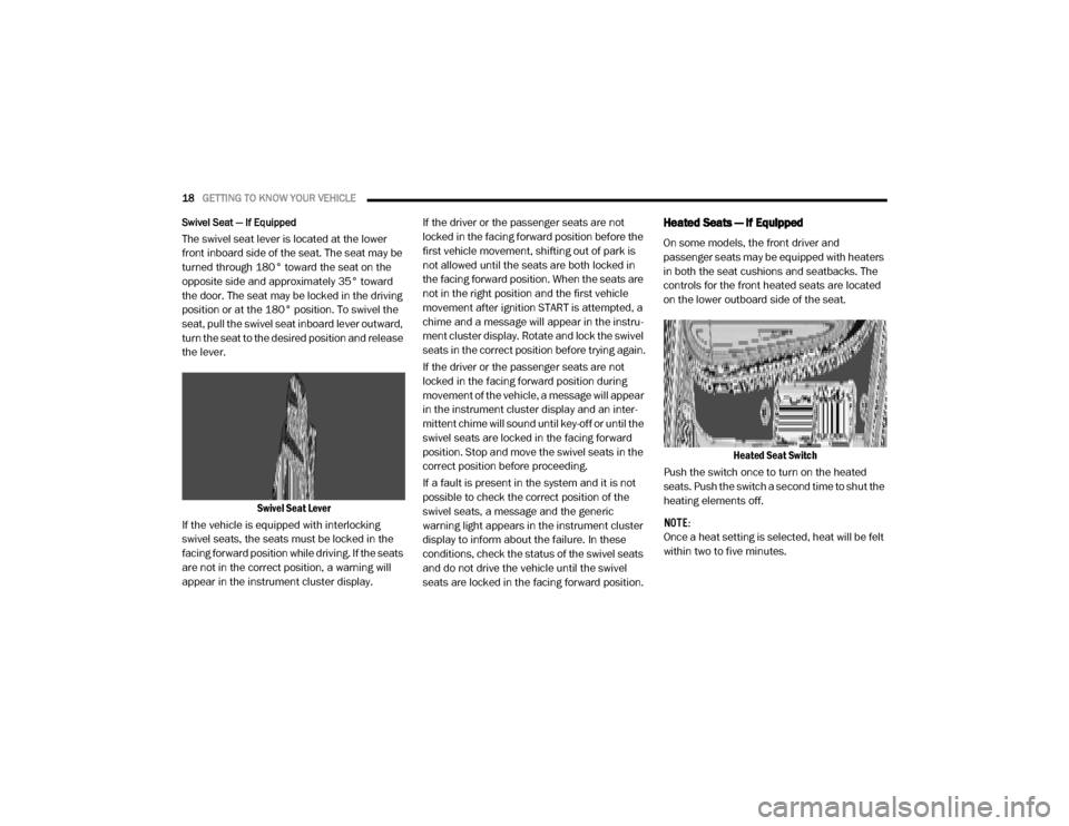
The swivel seat lever is located at the lower
front inboard side of the seat. The seat may be
turned through 180° toward the seat on the
opposite side and approximately 35° toward
the door. The seat may be locked in the driving
position or at the 180° position. To swivel the
seat, pull the swivel seat inboard lever outward,
turn the seat to the desired position and release
the lever.
Swivel Seat Lever
If the vehicle is equipped with interlocking
swivel seats, the seats must be locked in the
facing forward position while driving. If the seats
are not in the correct position, a warning will
appear in the instrument cluster display. If the driver or the passenger seats are not
locked in the facing forward position before the
first vehicle movement, shifting out of park is
not allowed until the seats are both locked in
the facing forward position. When the seats are
not in the right position and the first vehicle
movement after ignition START is attempted, a
chime and a message will appear in the instru
-
ment cluster display. Rotate and lock the swivel
seats in the correct position before trying again.
If the driver or the passenger seats are not
locked in the facing forward position during
movement of the vehicle, a message will appear
in the instrument cluster display and an inter -
mittent chime will sound until key-off or until the
swivel seats are locked in the facing forward
position. Stop and move the swivel seats in the
correct position before proceeding.
If a fault is present in the system and it is not
possible to check the correct position of the
swivel seats, a message and the generic
warning light appears in the instrument cluster
display to inform about the failure. In these
conditions, check the status of the swivel seats
and do not drive the vehicle until the swivel
seats are locked in the facing forward position.
Heated Seats — If Equipped
On some models, the front driver and
passenger seats may be equipped with heaters
in both the seat cushions and seatbacks. The
controls for the front heated seats are located
on the lower outboard side of the seat.
Heated Seat Switch
Push the switch once to turn on the heated
seats. Push the switch a second time to shut the
heating elements off.
NOTE:
Once a heat setting is selected, heat will be felt
within two to five minutes.
20_VF_OM_EN_US_t.book Page 18
Page 26 of 264
24GETTING TO KNOW YOUR VEHICLE
Daytime Running Lights (DRLs) — If
Equipped
NOTE:
When the headlights are turned on, the Daytime
Running Lights will be deactivated.
To activate the Daytime Running Lights (DRLs),
rotate the end of the multifunction lever to the
O (off) position.
NOTE:
The low beams and side/taillights will not be
on with DRLs.
In certain markets, the DRLs may be optional
and can be programmed to be on or off
through the Uconnect system screen. Refer
to “Uconnect Settings” in “Multimedia” for
further information.
The Daytime Running Lights will come on when -
ever the ignition is ON, the headlight switch is
off, and the turn signal is off.
High Beam/Low Beam Select Switch
With the low beams activated, pull the multi -
function lever toward the steering wheel to
switch the headlights to high beam. A high
beam symbol will be illuminated in the cluster to
indicate the high beams are on. Pull the lever a
second time to switch the headlights back to
low beam.
NOTE:
If the vehicle’s ignition is placed in the STOP
(OFF/LOCK) position, both high and low beam
headlights will also be turned off.
Flash-To-Pass
You can signal another vehicle with your head -
lights by partially pulling the multifunction lever
toward the steering wheel. This will cause the
high beam headlights to turn on until the lever
is released.
Parking Lights
These lights can only be turned on with ignition
key in the STOP (OFF/LOCK) position or
removed, by moving the end of the multifunc -
tion lever to O (off) position and then to the
headlight position. The warning light telltale in the instrument
panel comes on. The lights stay on until the next
ignition cycle is performed.
Follow Me Home/Headlight Delay
When this feature is selected, the driver can
choose to have the headlights remain on for a
preset period of time.
Activation
Remove the key or turn the ignition to the STOP
(OFF/LOCK) position, and pull the multifunction
lever toward the steering wheel, within two
minutes. Each time the lever is pulled, the acti
-
vation of the lights will be extended by 30
seconds. The activation of the lights can be
extended to a maximum of 210 seconds.
The warning light on the instrument panel will
light up and the corresponding message will
appear in the instrument cluster display for as
long as the function is activated. The warning
light comes on when the lever is operated and
stays on until the function is automatically deac -
tivated. Each movement of the lever only
increases the amount of time the lights stay on.
Deactivation
Pull the multifunction lever toward the steering
wheel and hold it for more than two seconds.
20_VF_OM_EN_US_t.book Page 24
Page 29 of 264
GETTING TO KNOW YOUR VEHICLE27
Dimmer Controls
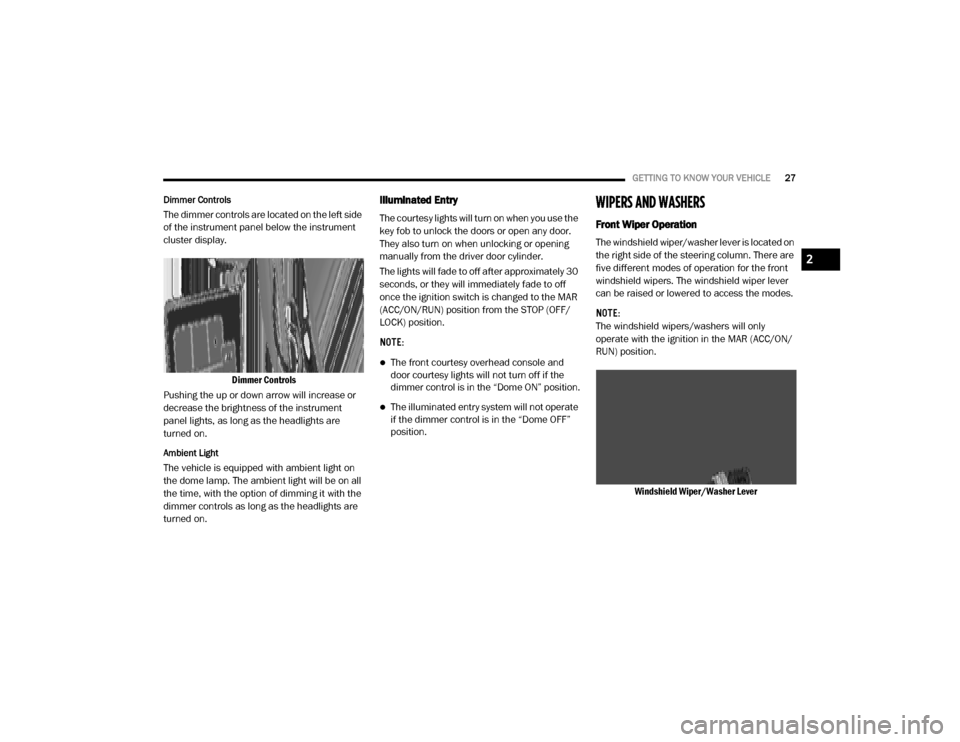
The dimmer controls are located on the left side
of the instrument panel below the instrument
cluster display.
Dimmer Controls
Pushing the up or down arrow will increase or
decrease the brightness of the instrument
panel lights, as long as the headlights are
turned on.
Ambient Light
The vehicle is equipped with ambient light on
the dome lamp. The ambient light will be on all
the time, with the option of dimming it with the
dimmer controls as long as the headlights are
turned on.
Illuminated Entry
The courtesy lights will turn on when you use the
key fob to unlock the doors or open any door.
They also turn on when unlocking or opening
manually from the driver door cylinder.
The lights will fade to off after approximately 30
seconds, or they will immediately fade to off
once the ignition switch is changed to the MAR
(ACC/ON/RUN) position from the STOP (OFF/
LOCK) position.
NOTE:
The front courtesy overhead console and
door courtesy lights will not turn off if the
dimmer control is in the “Dome ON” position.
The illuminated entry system will not operate
if the dimmer control is in the “Dome OFF”
position.
WIPERS AND WASHERS
Front Wiper Operation
The windshield wiper/washer lever is located on
the right side of the steering column. There are
five different modes of operation for the front
windshield wipers. The windshield wiper lever
can be raised or lowered to access the modes.
NOTE:
The windshield wipers/washers will only
operate with the ignition in the MAR (ACC/ON/
RUN) position.
Windshield Wiper/Washer Lever
2
20_VF_OM_EN_US_t.book Page 27
Page 44 of 264
42GETTING TO KNOW YOUR INSTRUMENT PANEL
Instrument Cluster Descriptions
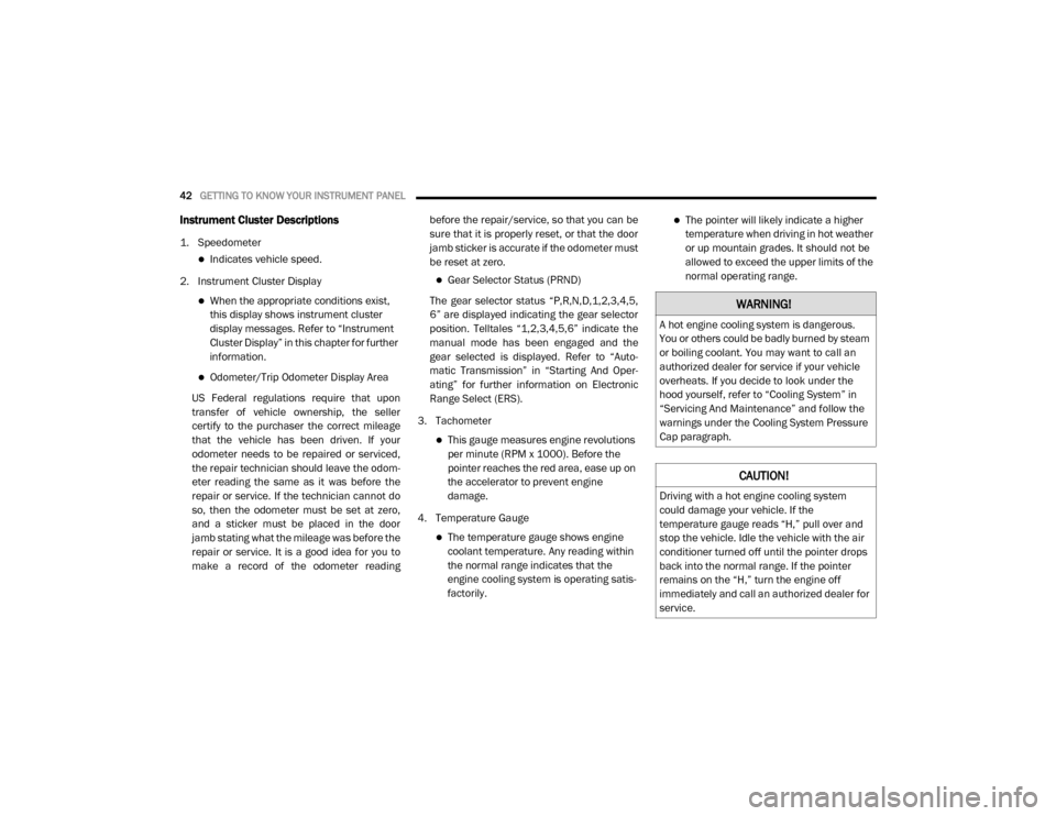
1. Speedometer
Indicates vehicle speed.
2. Instrument Cluster Display
When the appropriate conditions exist,
this display shows instrument cluster
display messages. Refer to “Instrument
Cluster Display” in this chapter for further
information.
Odometer/Trip Odometer Display Area
US Federal regulations require that upon
transfer of vehicle ownership, the seller
certify to the purchaser the correct mileage
that the vehicle has been driven. If your
odometer needs to be repaired or serviced,
the repair technician should leave the odom -
eter reading the same as it was before the
repair or service. If the technician cannot do
so, then the odometer must be set at zero,
and a sticker must be placed in the door
jamb stating what the mileage was before the
repair or service. It is a good idea for you to
make a record of the odometer reading before the repair/service, so that you can be
sure that it is properly reset, or that the door
jamb sticker is accurate if the odometer must
be reset at zero.
Gear Selector Status (PRND)
The gear selector status “P,R,N,D,1,2,3,4,5,
6” are displayed indicating the gear selector
position. Telltales “1,2,3,4,5,6” indicate the
manual mode has been engaged and the
gear selected is displayed. Refer to “Auto -
matic Transmission” in “Starting And Oper -
ating” for further information on Electronic
Range Select (ERS).
3. Tachometer
This gauge measures engine revolutions
per minute (RPM x 1000). Before the
pointer reaches the red area, ease up on
the accelerator to prevent engine
damage.
4. Temperature Gauge
The temperature gauge shows engine
coolant temperature. Any reading within
the normal range indicates that the
engine cooling system is operating satis-
factorily.
The pointer will likely indicate a higher
temperature when driving in hot weather
or up mountain grades. It should not be
allowed to exceed the upper limits of the
normal operating range.
WARNING!
A hot engine cooling system is dangerous.
You or others could be badly burned by steam
or boiling coolant. You may want to call an
authorized dealer for service if your vehicle
overheats. If you decide to look under the
hood yourself, refer to “Cooling System” in
“Servicing And Maintenance” and follow the
warnings under the Cooling System Pressure
Cap paragraph.
CAUTION!
Driving with a hot engine cooling system
could damage your vehicle. If the
temperature gauge reads “H,” pull over and
stop the vehicle. Idle the vehicle with the air
conditioner turned off until the pointer drops
back into the normal range. If the pointer
remains on the “H,” turn the engine off
immediately and call an authorized dealer for
service.
20_VF_OM_EN_US_t.book Page 42
Page 45 of 264
GETTING TO KNOW YOUR INSTRUMENT PANEL43
5. Fuel Gauge
The pointer shows the level of fuel in the
fuel tank when the ignition switch is in
the ON/RUN position.
The fuel pump symbol points to the
side of the vehicle where the fuel door is
located.
INSTRUMENT CLUSTER DISPLAY
Your vehicle will be equipped with an instru -
ment cluster display, which offers useful infor -
mation to the driver. With the ignition in the
STOP (OFF/LOCK) mode, opening/closing of a
door will activate the display for viewing, and
display the total miles, or kilometers, in the
odometer. Your instrument cluster display is
designed to display important information
about your vehicle’s systems and features.
Using a driver interactive display located on the
instrument panel, your instrument cluster
display can show you how systems are working
and give you warnings when they are not. The
steering wheel mounted controls allow you to
scroll through the main menus and submenus.
You can access the specific information you
want and make selections and adjustments.
Location And Controls
The instrument cluster display features a driver
interactive display that is located in the instru -
ment cluster.
Instrument Cluster Display
This system allows the driver to select a variety
of useful information by pushing the switches
mounted on the instrument panel. Examples of
menu items are:
Speed Beep
Buzzer Volume
Seat Belt Buzzer (Just Available After SBR
Disable Made By CHR Service)
Exit Menu If equipped with a Uconnect system, some
customer programmable features will display in
the radio. Refer to the “Uconnect Settings” in
“Multimedia” for further information.
The system allows the driver to select informa
-
tion by pushing the following buttons mounted
on the instrument panel to the left of the
steering column:
Display Control Buttons
NOTE:
The MODE button must be pushed prior to
pressing the up arrow and down arrow buttons.
3
20_VF_OM_EN_US_t.book Page 43
Page 46 of 264
44GETTING TO KNOW YOUR INSTRUMENT PANEL
MODE Button
Push and hold the MODE button for a time
longer than one second to access/select the
information screens or submenu screens of a
main menu item. Push and hold the MODE
button for two seconds to reset displayed/
selected features that can be reset.
Up Arrow Button
Push and release the up arrow
button to scroll upward through the
main menu and submenus or
adjust the illumination on the
instrument panel when the headlights are on.
Down Arrow Button
Push and release the down arrow
button to scroll downward through
the main menu and submenus or
adjust the illumination on the
instrument panel when the headlights are on.
Change Engine Oil
Your vehicle is equipped with an engine oil
change indicator system. The “Change Engine
Oil” message will display in the instrument
cluster display. The engine oil change indicator
system is duty cycle based, which means the engine oil change interval may fluctuate, depen
-
dent upon your personal driving style.
Unless reset, this message will continue to
display each time you turn the ignition switch to
the ON/RUN position. To turn off the message
temporarily, push and release the MODE
button. To reset the oil change indicator system
(after performing the scheduled maintenance),
refer to the following procedure.
1. Turn the ignition switch to the ON position (do not start the engine).
2. Fully push the accelerator pedal slowly, three times, within 10 seconds.
3. Turn the ignition switch to the OFF/LOCK position.
NOTE:
If the indicator message illuminates when you
start the vehicle, the oil change indicator
system did not reset. If necessary, repeat this
procedure.Display Setup Menu
The menu comprises a series of functions
arranged in a cycle. Push and release the up or
down arrow button to access the different
options and settings (setup). The setup menu can be activated by pushing
the
MODE button. Single pushes on the up or
down arrow button will scroll through the setup
menu options. The menu items include the
following functions:
Speed Beep
Buzzer Volume
Seat Belt Buzzer (Just Available After SBR
Disable Made By CHR Service)
Exit menu
NOTE:
If equipped, some customer programmable
features will display in the Uconnect system.
Refer to your Uconnect Owner’s Manual Supple -
ment for further information.
Selecting An Option Of The Main Menu Without
Submenu
1. Briefly push and release the MODE button
to select the main menu option to set.
2. Push and release the up or down arrow
button (by single pushes) to select the new
setting.
20_VF_OM_EN_US_t.book Page 44
Page 47 of 264
GETTING TO KNOW YOUR INSTRUMENT PANEL45
3. Briefly push and release the MODE button
to store the new setting and go back to the
main menu option previously selected.
Selecting An Option Of The Main Menu With
Submenu
1. Briefly push and release the MODE button
to display the first submenu option.
2. Push and release the up or down arrow
button (by single pushes) to scroll through
all the submenu options.
3. Briefly push and release the MODE button
to select the displayed submenu option and
to open the relevant setup menu.
4. Push and release the up or down arrow
button (by single pushes) to select the new
setting for this submenu option.
5. Briefly push and release the MODE button
to store the new setting and go back to the
previously selected submenu option.
6. Push and release and hold the MODE
button to return to the main menu (short
hold) or the main screen (longer hold).Values Displayed
NOTE:
All of the following items are accessed by
pressing the TRIP button.
Range
This indicates the distance which may be trav -
eled with the fuel remaining in the tank,
assuming that driving conditions will not
change. The message “----” will appear on the
display in the following cases:
Distance less than 30 miles (or 50 km).
The vehicle is parked for a long time with the
engine running.
NOTE:
The range depends on several factors: driving
style, type of route (freeway, residential, moun -
tain roads, etc.), conditions of use of the vehicle
(load, tire pressure, etc.). Trip planning must
take into account the above notes.
Travel Distance
This value shows the distance covered since the
last reset.
Average Fuel Consumption
This value shows the approximate average
consumption since the last reset.
Current Fuel Consumption
This indicates the fuel consumption. The value
is constantly updated. The message “----” will
appear on the display if the vehicle is parked
with the engine running.
Average Speed
This value shows the vehicle's average speed as
a function of the overall time elapsed since the
last reset.
Travel Time
This value shows the time elapsed since the last
reset.
3
20_VF_OM_EN_US_t.book Page 45
Page 48 of 264
46GETTING TO KNOW YOUR INSTRUMENT PANEL
Personal Settings
(Customer-Programmable Features)
Speed Beep
Buzzer Volume
Seat Belt Buzzer (Just Available After SBR
Disable Made By CHR Service)
Exit Menu
NOTE:
If equipped, some customer programmable
features will display in the Uconnect system.
Refer to “Uconnect Settings” in “Multimedia”
for further information.
TRIP COMPUTER
The Trip Computer is located in the instrument
cluster. It features a driver-interactive display
(displays information such as trip information,
range, fuel consumption, average speed, and
travel time).
NOTE:
The Uconnect System also has a Trip Computer
display and menus to customize the informa -
tion displayed in the cluster. For further infor -
mation, refer to “Uconnect Settings” in
“Multimedia”.
Trip Button
The TRIP button, located on the right steering
column stalk, can be used to display and to
reset the previously described values.
A short button push displays the different
values.
A long button push resets the system and
then starts a new trip.
New Trip
To reset:
Push and hold the TRIP button to reset the
system manually.
When the “Trip distance” reaches
99999.9 miles or kilometers or when the
“Travel time” reaches 999.59 (999 hours
and 59 minutes), the system is reset auto -
matically.
Disconnecting/Reconnecting the battery
resets the system.
NOTE:
If the reset operation occurs in the presence of
the screens concerning Trip A or Trip B, only the
information associated with Trip A or Trip B
functions will be reset. Start Of Trip Procedure
With the ignition on, push and hold the TRIP
button for over two seconds to reset trip infor
-
mation.
Exit Trip
To exit the Trip function, push the TRIP button
until all the trip menu items have been
displayed and the display returns to the main
menu.
Trip Functions
Both trip functions are resettable (reset — start
of new trip).
“Trip A” can be used to display the figures
relating to:
Trip Distance A
Average Fuel Consumption
Average Speed A
Travel Time A (Driving Time)
20_VF_OM_EN_US_t.book Page 46