lock RAM PROMASTER 2021 User Guide
[x] Cancel search | Manufacturer: RAM, Model Year: 2021, Model line: PROMASTER, Model: RAM PROMASTER 2021Pages: 288, PDF Size: 15.22 MB
Page 20 of 288

18GETTING TO KNOW YOUR VEHICLE
Lumbar Support — If Equipped
This feature allows you to increase or decrease
the amount of lumbar support. The lumbar
control knob is located on the rear upper
outboard side of the driver's seatback. Rotate
the control forward to increase and rearward to
decrease the desired amount of lumbar
support.
Suspension Seat — If Equipped
The seat is equipped with a mechanical spring
system and hydraulic shock absorber to ensure
maximum comfort and safety. The system of
springs also effectively absorbs impact from
uneven road surfaces. Damper Weight Adjustment
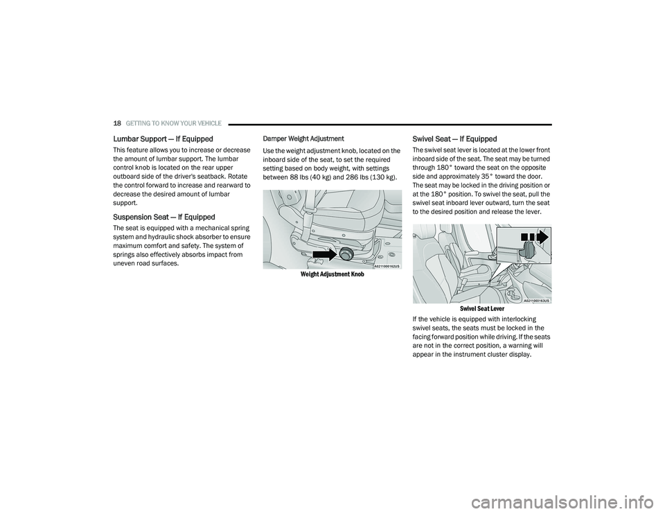
Use the weight adjustment knob, located on the
inboard side of the seat, to set the required
setting based on body weight, with settings
between 88 lbs (40 kg) and 286 lbs (130 kg).
Weight Adjustment Knob
Swivel Seat — If Equipped
The swivel seat lever is located at the lower front
inboard side of the seat. The seat may be turned
through 180° toward the seat on the opposite
side and approximately 35° toward the door.
The seat may be locked in the driving position or
at the 180° position. To swivel the seat, pull the
swivel seat inboard lever outward, turn the seat
to the desired position and release the lever.
Swivel Seat Lever
If the vehicle is equipped with interlocking
swivel seats, the seats must be locked in the
facing forward position while driving. If the seats
are not in the correct position, a warning will
appear in the instrument cluster display.
21_VF_OM_EN_USC_t.book Page 18
Page 21 of 288

GETTING TO KNOW YOUR VEHICLE19
If the driver or the passenger seats are not locked
in the facing forward position before the first
vehicle movement, shifting out of park is not
allowed until the seats are both locked in the
facing forward position. When the seats are not in
the right position and the first vehicle movement
after ignition START is attempted, a chime and a
message will appear in the instrument cluster
display. Rotate and lock the swivel seats in the
correct position before trying again.
If the driver or the passenger seats are not
locked in the facing forward position during
movement of the vehicle, a message will appear
in the instrument cluster display and an
intermittent chime will sound until key-off or
until the swivel seats are locked in the facing
forward position. Stop and move the swivel
seats in the correct position before proceeding.
If a fault is present in the system and it is not
possible to check the correct position of the
swivel seats, a message and the generic
warning light appears in the instrument cluster
display to inform about the failure. In these
conditions, check the status of the swivel seats
and do not drive the vehicle until the swivel
seats are locked in the facing forward position.HEATED SEATS — IF EQUIPPED
On some models, the front driver and
passenger seats may be equipped with heaters
in both the seat cushions and seatbacks. The
controls for the front heated seats are located
on the lower outboard side of the seat.
Heated Seat Switch
Push the switch once to turn on the heated
seats. Push the switch a second time to shut the
heating elements off. NOTE:
Once a heat setting is selected, heat will be felt
within two to five minutes.
WARNING!
Persons who are unable to feel pain to the
skin because of advanced age, chronic
illness, diabetes, spinal cord injury, medica
-
tion, alcohol use, exhaustion or other phys -
ical condition must exercise care when
using the seat heater. It may cause burns
even at low temperatures, especially if
used for long periods of time.
Do not place anything on the seat or seat -
back that insulates against heat, such as a
blanket or cushion. This may cause the seat
heater to overheat. Sitting in a seat that has
been overheated could cause serious
burns due to the increased surface
temperature of the seat.
2
21_VF_OM_EN_USC_t.book Page 19
Page 28 of 288

26GETTING TO KNOW YOUR VEHICLE
EXTERIOR LIGHTS
MULTIFUNCTION LEVER
The multifunction lever controls the operation
of the headlights, parking lights, turn signals,
headlight beam selection and the passing
lights. The multifunction lever is located on the
left side of the steering column.
Multifunction Lever
HEADLIGHTS
To turn on the headlights, turn the end of the
multifunction lever to the headlight position.
When the headlight switch is on, the parking
lights, taillights, license plate light, clearance
lights and instrument panel lights are also turned on. To turn off the headlights, turn the
end of the multifunction lever back to the O (off)
position.
DAYTIME RUNNING LIGHTS (DRLS) — IF
E
QUIPPED
NOTE:
When the headlights are turned on, the Daytime
Running Lights will be deactivated.
To activate the Daytime Running Lights, rotate
the end of the multifunction lever to the O (off)
position.
For vehicles sold in Canada, the Daytime
Running Lights will automatically deactivate
when the front fog lights are turned on. When
the end of the multifunction lever is turned to
the O (off) position with the DRLs on, the
parking lights and license plate lights will also
turn on.
NOTE:
The low beams and side/taillights will not be on
with DRLs.
The Daytime Running Lights will come on
whenever the ignition is ON, the headlight
switch is off, and the turn signal is off.
HIGH/LOW BEAM SWITCH
With the low beams activated, pull the
multifunction lever toward the steering wheel to
turn on the high beams. The High Beam
Indicator Light will illuminate in the instrument
cluster to indicated that the high beams are on.
Pull the multifunction lever a second time to
switch the headlights back to low beam. When
the ignition is placed in the OFF position, both
the high and low beams will turn off.
FLASH-TO-PASS
You can signal another vehicle with your
headlights by lightly pulling the multifunction
lever toward you. This will cause the high beam
headlights to turn on, and remain on, until the
lever is released.
PARKING LIGHTS
These lights can be turned on, with the ignition
key in the STOP (OFF/LOCK) position or
removed, by moving the end of the
multifunction lever to O (off) position and then
to the headlight position.
The indicator light in the instrument panel
comes on. The lights stay on until the next
ignition cycle is performed.
21_VF_OM_EN_USC_t.book Page 26
Page 29 of 288

GETTING TO KNOW YOUR VEHICLE27
FOLLOW ME HOME/HEADLIGHT DELAY
When this feature is selected, the driver can
choose to have the headlights remain on for a
preset period of time after the engine is turned
off.
Activation
Remove the key or turn the ignition to the STOP
(OFF/LOCK) position, and pull the multifunction
lever toward the steering wheel within two
minutes. Each time the lever is pulled, the
activation of the lights will be extended by
30 seconds. The activation of the lights can be
extended to a maximum of 210 seconds.
The indicator light on the instrument panel will
light up and the corresponding message will
appear in the instrument cluster display for as
long as the function is activated. The indicator
light comes on when the lever is operated and
stays on until the function is automatically
deactivated. Each movement of the lever only
increases the amount of time the lights stay on.
Deactivation
Pull the multifunction lever toward the steering
wheel and hold it for more than two seconds.
FOG LIGHTS — IF EQUIPPED
The fog light switch is located on the center
stack of the instrument panel, just below the
climate controls.
Push the switch once to turn the fog
lights on. Push the switch a second
time to turn the fog lights off.
NOTE:
If the vehicle’s ignition is turned off, the fog
lights will also turn off.
TURN SIGNALS
Move the multifunction lever up or down and
the arrows on each side of the instrument
cluster will flash to show proper operation of the
turn signals.
NOTE:
If either light remains on and does not flash, or
there is a very fast flash rate, check for a defec -
tive outside light bulb.
LANE CHANGE ASSIST
Lightly push the multifunction lever up or down,
without moving beyond the detent, and the turn
signal will flash five times then automatically
turn off.
BATTERY SAVER
To protect the life of your vehicle’s battery,
when the ignition is OFF and any door is left ajar
for 15 minutes, the interior lights will
automatically turn off.
NOTE:
Battery saver mode is cancelled if the ignition is
placed in the MAR (ACC/ON/RUN) position.
2
21_VF_OM_EN_USC_t.book Page 27
Page 32 of 288

30GETTING TO KNOW YOUR VEHICLE
ILLUMINATED ENTRY
The courtesy lights will turn on when you use the
key fob to unlock the doors or open any door.
They also turn on when unlocking or opening
manually from the driver door cylinder.
The lights will fade to off after approximately
30 seconds, or they will immediately fade to
off once the ignition switch is changed to the
MAR (ACC/ON/RUN) position from the
STOP (OFF/LOCK) position.
NOTE:
The front courtesy overhead console and
door courtesy lights will not turn off if the
dimmer control is in the “Dome ON” position.
The illuminated entry system will not operate
if the dimmer control is in the “Dome OFF”
position.
WIPERS AND WASHERS
WINDSHIELD WIPER OPERATION
The windshield wiper/washer lever is located on
the right side of the steering column. There are
five different modes of operation for the front
windshield wipers. The windshield wiper lever
can be raised or lowered to access the modes.
NOTE:
The windshield wipers/washers will
only operate with the ignition in the
MAR (ACC/ON/RUN) position.
Windshield Wiper/Washer Lever
Intermittent Wipers
Push the lever downward to the first detent and
rotate the center ring to use one of the four
intermittent wiper settings when weather
conditions make a single wiping cycle, with a
variable delay between cycles, desirable.
Push the lever downward to the second detent,
and the wipers will operate at low speed. Push
the lever downward to the third detent, and the
wipers will operate at high speed.
Windshield Washers
To use the washer, pull the windshield wiper/
washer lever toward the steering wheel to
activate. The wipers will activate automatically
for three cycles after the lever is released, and
then resume the intermittent interval previously
selected.
If the lever is pulled while in the off position, the
wipers will operate for three cycles and then
turn off.
21_VF_OM_EN_USC_t.book Page 30
Page 35 of 288

GETTING TO KNOW YOUR VEHICLE33
Temperature Control
Temperature Control regulates the temperature
of the air forced through the climate system.
The temperature increases as you
turn the temperature control knob
clockwise.
The temperature decreases as you
turn the temperature control knob
counterclockwise.
Blower Control
Blower Control regulates the amount
of air forced through the climate
system. There are seven blower
speeds available. The blower speed
increases as you turn the blower control knob
clockwise from the lowest blower setting. The
blower speed decreases as you turn the blower
control knob counterclockwise.
NOTE:
Depending on the configuration, your vehicle
may be equipped with four blower speeds.
Mode Control
Turn the mode control knob to change
the airflow distribution mode. The
airflow distribution mode can be
adjusted so air comes from the
instrument panel outlets, floor outlets, defrost
outlets and demist outlets.
Panel Mode
Air comes from the outlets in the
instrument panel. Each of these
outlets can be individually adjusted to
direct the flow of air. The air vanes of
the center outlets and outboard outlets can be
moved up and down or side to side to regulate
airflow direction. There is a shut off wheel
located below the air vents to shut off or adjust
the amount of airflow from these outlets.
Bi-Level Mode
Air comes from the instrument panel
outlets and floor outlets. A slight
amount of air is directed through
the defrost and side window
demister outlets.
NOTE:
Bi-Level mode is designed under comfort condi
-
tions to provide cooler air out of the panel
outlets and warmer air from the floor outlets.
Floor Mode
Air comes from the floor outlets.
A slight amount of air is directed
through the defrost and side window
demister outlets.
Mix Mode
Air is directed through the floor,
defrost, and side window demister
outlets. This setting works best in cold
or snowy conditions that require extra
heat to the windshield. This setting is good for
maintaining comfort while reducing moisture on
the windshield.
Climate Control OFF
To turn the Climate Controls off, turn
the blower control knob to the OFF (O)
position.
2
21_VF_OM_EN_USC_t.book Page 33
Page 41 of 288

GETTING TO KNOW YOUR VEHICLE39
WINDOWS
POWER WINDOWS
The control on the left front door panel has
switches that control all power windows. There
is a single opening and closing switch on the
front passenger door for passenger window
control.
Power Window Switches
NOTE:
The Key Off Power Delay feature will allow the
power windows to operate for up to three
minutes after the ignition is placed in the STOP
(OFF/LOCK) position. This feature is cancelled
when either front door is opened.
Automatic Window Features
Auto-Down Feature — If Equipped
The window switches may be equipped with an
Auto-Down feature. Push the window switch for
half a second, release, and the window will go
down automatically.
To stop the window from going all the way down
during the auto-down operation, pull up or push
down on the switch briefly. To open the window part way, lift the window
switch to the detent for less than half a second
and release it to stop the window.
WINDOW BAR GRATES — IF EQUIPPED
This vehicle may be equipped with metal grates
over the sliding door windows. This feature is a
part of the vehicle’s safety system, and is
designed to protect you and your passengers in
the event of an accident.
Window Bar Grates
WARNING!
Never leave children alone in a vehicle, or
with access to an unlocked vehicle.
Allowing children to be in a vehicle unat -
tended is dangerous for a number of
reasons. A child or others could be seriously
or fatally injured. Children should be
warned not to touch the parking brake,
brake pedal or the gear selector.
Do not leave the key fob in or near the
vehicle or in a location accessible to chil -
dren. A child could operate power windows,
other controls, or move the vehicle.
WARNING!
The metal grates over the sliding door windows
are designed to protect you in the event of an
accident. Modification or removal of the grates
could lead to serious injury or death.
2
21_VF_OM_EN_USC_t.book Page 39
Page 43 of 288

GETTING TO KNOW YOUR VEHICLE41
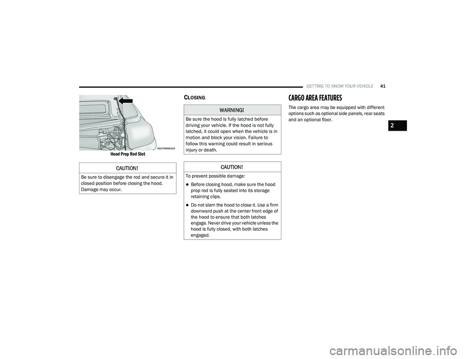
Hood Prop Rod Slot
CLOSINGCARGO AREA FEATURES
The cargo area may be equipped with different
options such as optional side panels, rear seats
and an optional floor.
CAUTION!
Be sure to disengage the rod and secure it in
closed position before closing the hood.
Damage may occur.
WARNING!
Be sure the hood is fully latched before
driving your vehicle. If the hood is not fully
latched, it could open when the vehicle is in
motion and block your vision. Failure to
follow this warning could result in serious
injury or death.
CAUTION!
To prevent possible damage:
Before closing hood, make sure the hood
prop rod is fully seated into its storage
retaining clips.
Do not slam the hood to close it. Use a firm
downward push at the center front edge of
the hood to ensure that both latches
engage. Never drive your vehicle unless the
hood is fully closed, with both latches
engaged.
2
21_VF_OM_EN_USC_t.book Page 41
Page 46 of 288

44GETTING TO KNOW YOUR INSTRUMENT PANEL
5. Fuel Gauge
The pointer shows the level of fuel in the
fuel tank when the ignition switch is in
the ON/RUN position.
The fuel pump symbol points
to the side of the vehicle where
the fuel door is located
Ú page 75.
INSTRUMENT CLUSTER DISPLAY
Your vehicle will be equipped with an
instrument cluster display, which offers useful
information to the driver. With the ignition in the
STOP (OFF/LOCK) mode, opening/closing of a
door will activate the display for viewing, and
display the total miles, or kilometers, in the
odometer. Your instrument cluster display is
designed to display important information
about your vehicle’s systems and features.
Using a driver interactive display located on the
instrument panel, your instrument cluster
display can show you how systems are working
and give you warnings when they are not. The
steering wheel mounted controls allow you to
scroll through the main menus and submenus.
You can access the specific information you
want and make selections and adjustments.
LOCATION AND CONTROLS
The instrument cluster display features a driver
interactive display that is located in the
instrument cluster.
Instrument Cluster Display
This system allows the driver to select a variety
of useful information by pushing the switches
mounted on the instrument panel. Examples of
menu items are:
Speed Beep
Buzzer Volume
Seat Belt Buzzer
Exit Menu
CAUTION!
Driving with a hot engine cooling system could
damage your vehicle. If the temperature gauge
reads “H,” pull over and stop the vehicle. Idle
the vehicle with the air conditioner turned off
until the pointer drops back into the normal
range. If the pointer remains on the “H,” turn
the engine off immediately and call an
authorized dealer for service.
21_VF_OM_EN_USC_t.book Page 44
Page 47 of 288

GETTING TO KNOW YOUR INSTRUMENT PANEL45
If equipped with a Uconnect system, some
customer programmable features will display in
the radio Úpage 89.
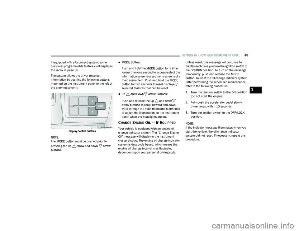
The system allows the driver to select
information by pushing the following buttons
mounted on the instrument panel to the left of
the steering column:
Display Control Buttons
NOTE:
The MODE button must be pushed prior to
pressing the up arrow and down arrow
buttons .MODE Button:
Push and hold the MODE button for a time
longer than one second to access/select the
information screens or submenu screens of a
main menu item. Push and hold the MODE
button for two seconds to reset displayed/
selected features that can be reset.
Up And Down Arrow Buttons:
Push and release the up and down
arrow buttons to scroll upward and down -
ward through the main menu and submenus
or adjust the illumination on the instrument
panel when the headlights are on.
CHANGE ENGINE OIL — IF EQUIPPED
Your vehicle is equipped with an engine oil
change indicator system. The “Change Engine
Oil” message will display in the instrument
cluster display. The engine oil change indicator
system is duty cycle based, which means the
engine oil change interval may fluctuate,
dependent upon your personal driving style. Unless reset, this message will continue to
display each time you turn the ignition switch to
the ON/RUN position. To turn off the message
temporarily, push and release the
MODE
button . To reset the oil change indicator system
(after performing the scheduled maintenance),
refer to the following procedure.
1. Turn the ignition switch to the ON position (do not start the engine).
2. Fully push the accelerator pedal slowly, three times, within 10 seconds.
3. Turn the ignition switch to the OFF/LOCK position.
NOTE:
If the indicator message illuminates when you
start the vehicle, the oil change indicator
system did not reset. If necessary, repeat this
procedure.
3
21_VF_OM_EN_USC_t.book Page 45