ECO mode RAM PROMASTER 2021 Owner's Manual
[x] Cancel search | Manufacturer: RAM, Model Year: 2021, Model line: PROMASTER, Model: RAM PROMASTER 2021Pages: 288, PDF Size: 15.22 MB
Page 117 of 288
MULTIMEDIA115
NOTE:
If there are no phones currently connected
with the system, a pop-up will appear asking
if you would like to pair a mobile phone.
This pop-up only appears when the user
enters phone mode and no other device(s)
have previously been paired.
If the system has a phone previously paired,
even if no phone is currently connected with
the system, this pop-up will not appear.
3. Select “Yes” to begin the pairing process.
4. Search for available devices on your Bluetooth®-enabled mobile phone.
Press the Settings button on your mobile
phone.
Select Bluetooth® and ensure it is
enabled. Once enabled, the mobile
phone will begin to search for Bluetooth®
connections. 5. If “No” is selected, and you still would like to
pair a mobile phone, press the Pairing or
Settings button from the Uconnect Phone
main screen.
Press the Paired Phones button.
Search for available devices on your
Bluetooth®-enabled mobile phone (see
below). When prompted on the phone,
select “Uconnect” and accept the
connection request.
6. Uconnect Phone will display an in-progress screen while the system is connecting.
7. When your mobile phone finds the Uconnect system, select “Uconnect.”
8. When prompted on the mobile phone, accept the connection request from
Uconnect Phone. 9. When the pairing process has successfully
completed, the system will prompt you to
choose whether or not this is your favorite
phone. Selecting “Yes” will make this phone
the highest priority. This phone will take
precedence over other paired phones within
range and will connect to the Uconnect
system automatically when entering the
vehicle. Only one mobile phone and/or one
Bluetooth® audio device can be connected
to the Uconnect system at a time. If “No” is
selected, simply select “Uconnect” from the
mobile phone/audio device Bluetooth®
screen, and the Uconnect system will
reconnect to the Bluetooth® device.
NOTE:
For phones which are not made a favorite, the
phone priority is determined by the order in
which it was paired. The latest phone paired will
have the higher priority.
NOTE:
During the pairing procedure, you may receive a
pop-up on your mobile phone for the Uconnect
System to access your “messages” and
“contacts”. Selecting “Ok” or “Allow” will sync
your contacts with the Uconnect System.
5
21_VF_OM_EN_USC_t.book Page 115
Page 126 of 288
124MULTIMEDIA
To enable Siri, push and hold, then release the
Uconnect Voice Recognition (VR) button on the
steering wheel. After you hear a double beep,
you can ask Siri to play podcasts and music, get
directions, read text messages, and many other
useful requests.
Bluetooth® Communication Link
Mobile phones may lose connection to the
Uconnect Phone. When this happens, the
connection can generally be re-established by
restarting the mobile phone. Your mobile phone
is recommended to remain in Bluetooth® ON
mode.
Power-Up
After switching the ignition key from OFF to
either the ON/RUN or ACC position, or after a
language change, you must wait at least
15 seconds prior to using the system
Úpage 274.NAVIGATION MODE — IF EQUIPPED
OPERATING NAVIGATION MODE — IF
E
QUIPPED
Planning A Route
Using the search bar provides a wide range of
ways to find places and then navigate to them.
You can search for your destination in different
ways:
A specific address
A partial address
A type of place
A zip code
A city to navigate to a city center
A Point of Interest (POI) near your current
location
Latitude and longitude coordinates Using Search
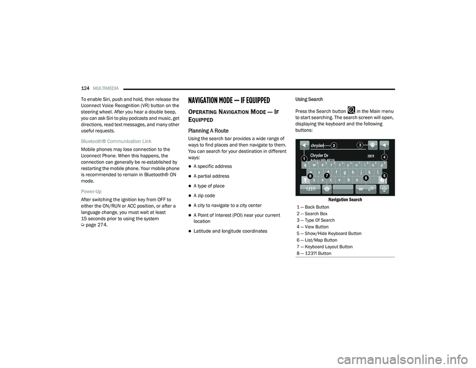
Press the Search button in the Main menu
to start searching. The search screen will open,
displaying the keyboard and the following
buttons:
Navigation Search
1 — Back Button
2 — Search Box
3 — Type Of Search
4 — View Button
5 — Show/Hide Keyboard Button
6 — List/Map Button
7 — Keyboard Layout Button
8 — 123?! Button
21_VF_OM_EN_USC_t.book Page 124
Page 148 of 288

146MULTIMEDIA
STEERING WHEEL AUDIO CONTROLS
The remote sound system controls are located
on the surface of the steering wheel.
Remote Sound System Controls
Pushing the top of the left-hand switch will
increase the volume, and pushing the bottom of
the switch will decrease the volume.
Pushing the Voice Recognition (VR) button
below the volume controls will begin your voice
command functions Ú page 22.
The function of the right-hand control is
different depending on which mode you are in.
The following describes the right-hand control
operation in each mode.
RADIO OPERATION
Pushing the top of the right-hand switch will
“Scan” up for the next listenable station, and
pushing the bottom of the right-hand switch will
“Scan” down for the next listenable station.
Pushing the Phone pick up button on top of the
of the Scan buttons will open a phone call.
Pushing the Phone hang up button below the
Scan buttons will close a phone call.
PLAYER OPERATION
Pushing the switch up once will go to the next
track on the Player. Pushing the switch down
once will go to the beginning of the current track
or to the beginning of the previous track if it is
within one second after the current track begins
to play.
If you push the switch up or down twice, it plays
the second track; three times, it will play the
third, etc.
RAM TELEMATICS - IF EQUIPPED
Ram Telematics is designed to help improve
safety, efficiency, and productivity. It gives you
complete visibility of your fleet options, whether
from behind a desk or on a mobile device while
you are on the go. You can log-in to view near
real-time and historical activity, including
location, vehicle heath, and driver performance.
Activating Ram Telematics In Your Vehicles
Before you get started you will need:
The Vehicle Identification Number (VIN) of
each vehicle you want to activate.
Your main user’s log-in and password; new
customers will be asked to register.
If you are a new customer, you will need
company credit card information or invoice
number as further proof of customer identifi -
cation. Don’t worry, you will not be charged.
21_VF_OM_EN_USC_t.book Page 146
Page 154 of 288
152SAFETY
ESC Partial Off
This mode is entered by momentarily pushing
the ESC OFF button.
When in the “Partial Off” mode, the TCS portion
of ESC, except for the “limited slip” feature
described in the TCS section, has been disabled
and the ESC OFF Indicator Light will be
illuminated. When in the “Partial Off” mode,
ESC will operate without engine torque
management. This mode is intended to be used
if the vehicle is in deep snow, sand or gravel
conditions and more wheel spin than ESC would
normally allow is required to gain traction.
To turn ESC on again, momentarily push the
ESC OFF button. This will restore the normal
“ESC On” mode of operation. NOTE:
To improve the vehicle's traction when driving
with snow chains, or starting off in deep snow,
sand or gravel, it may be desirable to switch to
the “Partial Off” mode by pushing the ESC OFF
button. Once the situation requiring ESC to be
switched to the “Partial Off” mode is overcome,
turn ESC back on by momentarily pushing the
ESC OFF button. This may be done while the
vehicle is in motion.ESC Activation/Malfunction Indicator Light
And ESC OFF Indicator Light
The ESC Activation/Malfunction
Indicator Light in the instrument
cluster will come on when the ignition
is turned to the ON mode. It should go
out with the engine running. If the ESC
Activation/Malfunction Indicator Light comes
on continuously with the engine running, a
malfunction has been detected in the ESC
system. If this light remains on after several
ignition cycles, and the vehicle has been driven
several miles (kilometers) at speeds greater
than 30 mph (48 km/h), see an authorized
dealer as soon as possible to have the problem
diagnosed and corrected.
The ESC Activation/Malfunction Indicator Light
starts to flash as soon as the tires lose traction
and the ESC system becomes active. The ESC
Activation/Malfunction Indicator Light also
flashes when TCS is active. If the ESC
Activation/Malfunction Indicator Light begins to
flash during acceleration, ease up on the
accelerator and apply as little throttle as
possible. Be sure to adapt your speed and
driving to the prevailing road conditions.
WARNING!
When in “Partial Off” mode, the TCS func -
tionality of ESC, (except for the limited slip
feature described in the TCS section), has
been disabled and the ESC OFF Indicator
Light will be illuminated. When in “Partial
Off” mode, the engine power reduction
feature of TCS is disabled, and the
enhanced vehicle stability offered by the
ESC system is reduced.
Trailer Sway Control (TSC) is disabled when
the ESC system is in the “Partial Off” mode.
21_VF_OM_EN_USC_t.book Page 152
Page 155 of 288
SAFETY153
The ESC OFF Indicator Light indicates
that the Electronic Stability Control
(ESC) is in a reduced mode.
NOTE:
The ESC Activation/Malfunction Indicator
Light and the ESC OFF Indicator Light come
on momentarily each time the ignition switch
is placed in the ON position.
Each time the ignition is placed in the ON
position, the ESC system will be on even if it
was turned off previously.
The ESC system will make buzzing or clicking
sounds when it is active. This is normal; the
sounds will stop when ESC becomes inactive
following the maneuver that caused the ESC
activation.
Hill Start Assist (HSA)
The HSA system is designed to assist the driver
when starting a vehicle from a stop on a hill.
HSA will maintain the level of brake pressure
the driver applied for a short period of time after
the driver takes their foot off of the brake pedal.
If the driver does not apply the throttle during
this short period of time, the system will release
brake pressure and the vehicle will roll down the
hill. The system will release brake pressure in
proportion to the amount of throttle applied as
the vehicle starts to move in the intended
direction of travel.
HSA Activation Criteria
The following criteria must be met in order for
HSA to activate:
The vehicle must be stopped.
The vehicle must be on a 6% (approximate)
grade or greater hill.
Gear selection matches vehicle uphill direction
(i.e., vehicle facing uphill is in forward gear;
vehicle backing uphill is in REVERSE gear).
HSA will work in REVERSE and all forward gears
when the activation criteria have been met. The
system will not activate if the vehicle is placed
in NEUTRAL or PARK.
WARNING!
There may be situations on minor hills with a
loaded vehicle, or while pulling a trailer, when
the system will not activate and slight rolling
may occur. This could cause a collision with
another vehicle or object. Always remember
the driver is responsible for braking the
vehicle.
6
21_VF_OM_EN_USC_t.book Page 153
Page 156 of 288
154SAFETY
Towing With HSA
HSA will also provide assistance to mitigate roll
back while towing a trailer.
Traction Control System (TCS)
TCS monitors the amount of wheel spin of each
of the driven wheels. If wheel spin is detected,
brake pressure is applied to the slipping
wheel(s) and engine power is reduced, to
provide enhanced acceleration and stability. A
feature of the TCS, Brake Limited Differential
(BLD), functions similarly to a limited slip
differential and controls the wheel spin across a
driven axle. If one wheel on a driven axle is
spinning faster than the other, the system will
apply the brake of the spinning wheel. This will
allow more engine torque to be applied to the
wheel that is not spinning. This feature remains
active even if the ESC is in the “Partial Off”
mode.
The ESC Activation/Malfunction Indicator Light
(in the instrument cluster) will start to flash as
soon as the tires lose traction and the wheels
begin to spin. This indicates that the TCS is
active. If the indicator light flashes during
acceleration, ease up on the accelerator and
apply as little throttle as possible. Be sure to
adapt your speed and driving to the prevailing
road conditions, and do not switch off the ESC
or TCS.
Trailer Sway Control (TSC) — If Equipped
TSC uses sensors in the vehicle to recognize an
excessively swaying trailer and will take the
appropriate actions to attempt to stop the sway.
The system may reduce engine power and apply
the brake of the appropriate wheel(s) to
counteract the sway of the trailer.
WARNING!
If you use a trailer brake controller with your
trailer, the trailer brakes may be activated
and deactivated with the brake switch. If
so, there may not be enough brake pres -
sure to hold both the vehicle and the trailer
on a hill when the brake pedal is released.
In order to avoid rolling down an incline
while resuming acceleration, manually acti -
vate the trailer brake or apply more vehicle
brake pressure prior to releasing the brake
pedal.
HSA is not a parking brake. Always apply
the parking brake fully when exiting your
vehicle. Also, be certain to place the trans -
mission in PARK.
Failure to follow these warnings can result
in a collision or serious personal injury.
WARNING!
The TCS cannot prevent the natural laws of
physics from acting on the vehicle, nor can
it increase the traction afforded.
The TCS cannot prevent collisions,
including those resulting from excessive
speed in turns, or hydroplaning.
The capabilities of a TCS-equipped vehicle
must never be exploited in a reckless or
dangerous manner, which could jeopardize
the user's safety or the safety of others.
21_VF_OM_EN_USC_t.book Page 154
Page 157 of 288
SAFETY155
NOTE:
TSC cannot stop all trailers from swaying.
Always use caution when towing a trailer and
follow the trailer tongue weight recommenda -
tions Ú page 78.
When TSC is functioning, the ESC Activation/
Malfunction Indicator Light will flash, the engine
power may be reduced, and you may feel the
brakes being applied to individual wheels to
attempt to stop the trailer from swaying. TSC is
disabled when the ESC system is in the “Partial
Off” mode.AUXILIARY DRIVING SYSTEMS
BLIND SPOT MONITORING (BS M) — IF
E
QUIPPED
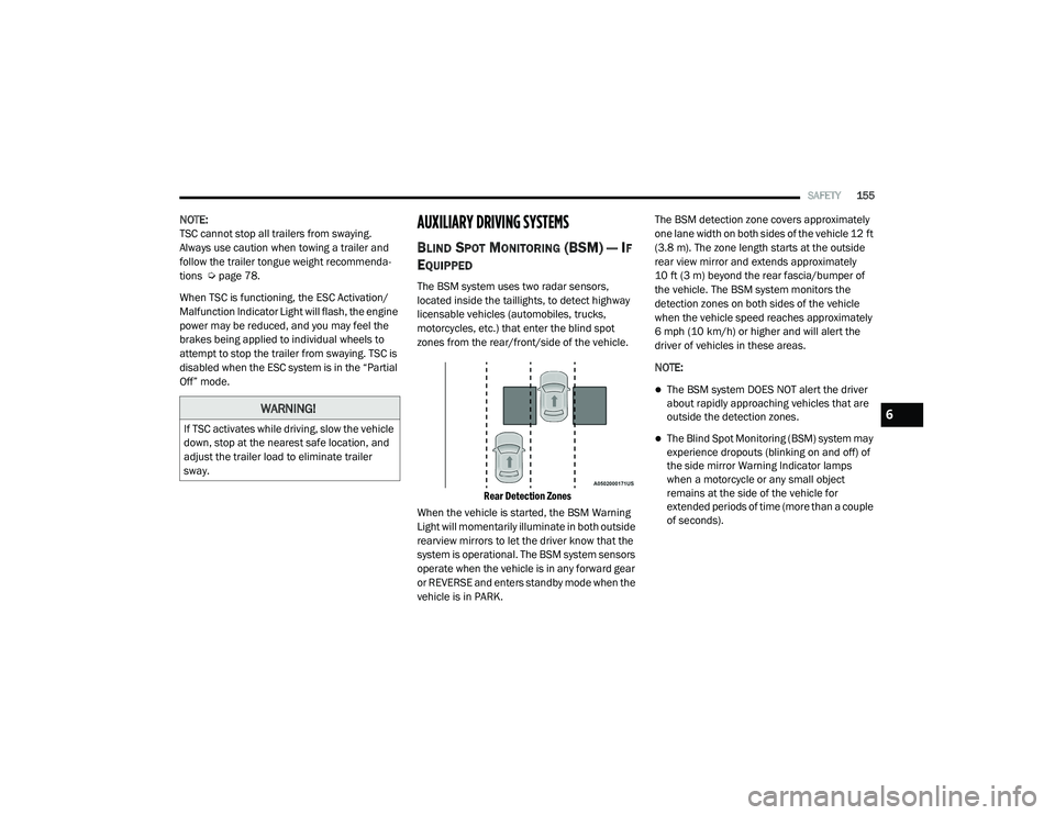
The BSM system uses two radar sensors,
located inside the taillights, to detect highway
licensable vehicles (automobiles, trucks,
motorcycles, etc.) that enter the blind spot
zones from the rear/front/side of the vehicle.
Rear Detection Zones
When the vehicle is started, the BSM Warning
Light will momentarily illuminate in both outside
rearview mirrors to let the driver know that the
system is operational. The BSM system sensors
operate when the vehicle is in any forward gear
or REVERSE and enters standby mode when the
vehicle is in PARK. The BSM detection zone covers approximately
one lane width on both sides of the vehicle 12 ft
(3.8 m). The zone length starts at the outside
rear view mirror and extends approximately
10 ft (3 m) beyond the rear fascia/bumper of
the vehicle. The BSM system monitors the
detection zones on both sides of the vehicle
when the vehicle speed reaches approximately
6 mph (10 km/h) or higher and will alert the
driver of vehicles in these areas.
NOTE:
The BSM system DOES NOT alert the driver
about rapidly approaching vehicles that are
outside the detection zones.
The Blind Spot Monitoring (BSM) system may
experience dropouts (blinking on and off) of
the side mirror Warning Indicator lamps
when a motorcycle or any small object
remains at the side of the vehicle for
extended periods of time (more than a couple
of seconds).
WARNING!
If TSC activates while driving, slow the vehicle
down, stop at the nearest safe location, and
adjust the trailer load to eliminate trailer
sway.
6
21_VF_OM_EN_USC_t.book Page 155
Page 161 of 288
SAFETY159
NOTE:
Whenever an audible alert is requested by the
BSM system, the radio is also muted.
When the system is in RCP, the system shall
respond with both visual and audible alerts
when a detected object is present. Whenever
an audible alert is requested, the radio is also
muted. Turn/hazard signal status is ignored;
the RCP state always requests the chime.
Blind Spot Alert Off
When the BSM system is turned off there will be
no visual or audible alerts from either the BSM
or RCP systems.
NOTE:
The BSM system will store the current operating
mode when the vehicle is shut off. Each time
the vehicle is started the previously stored
mode will be recalled and used.
FORWARD COLLISION WARNING (FCW)
W
ITH MITIGATION — IF EQUIPPED
The FCW with Mitigation system provides the
driver with audible warnings, visual warnings
(within the instrument cluster display), and may
apply a brake jerk to warn the driver when it
detects a potential frontal collision. The warnings and limited braking are intended
to provide the driver with enough time to react,
avoid or mitigate the potential collision.
NOTE:
FCW monitors the information from the forward
looking sensors as well as the Electronic Brake
Controller (EBC), to calculate the probability of a
forward collision. When the system determines
that a forward collision is probable, the driver
will be provided with audible and visual warn-
ings as well as a possible brake jerk warning.
If the driver does not take action based upon
these progressive warnings, then the system
will provide a limited level of active braking to
help slow the vehicle and mitigate the potential
forward collision. If the driver reacts to the warn
-
ings by braking and the system determines that
the driver intends to avoid the collision by
braking but has not applied sufficient brake
force, the system will compensate and provide
additional brake force as required.
If a FCW with Mitigation event begins at a speed
below 26 mph (42 km/h), the system may
provide the maximum braking possible to miti -
gate the potential forward collision. Vehicles
With Automatic Transmission: After the end of the intervention of automatic braking, the trans
-
mission may remain in last gear stored — there -
fore the vehicle could lurch forward, once the
brakes release a few seconds later. If the
Forward Collision Warning with Mitigation event
stops the vehicle completely, the system will
hold the vehicle at standstill for two seconds
and then release the brakes.
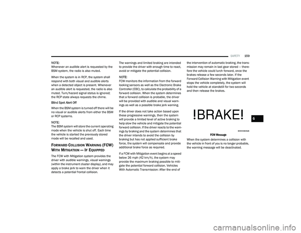
FCW Message
When the system determines a collision with
the vehicle in front of you is no longer probable,
the warning message will be deactivated.
6
21_VF_OM_EN_USC_t.book Page 159
Page 166 of 288

164SAFETY
Check TPMS Warnings
The Tire Pressure Monitoring System Warning
Light will flash on and off for 75 seconds and
remain on solid when a system fault is detected,
an audible chime will be activated and the “Tire
Pressure Monitoring Unavailable” message will
display. If the ignition key is cycled, this
sequence will repeat providing the system fault
still exists. The TPMS Warning Light will turn off
when the fault condition no longer exists. A
system fault can occur with any of the following
scenarios:
Jamming due to electronic devices or driving
next to facilities emitting the same radio
frequencies as the TPMS sensors
Installing some form of aftermarket window
tinting that affects radio wave signals
Snow or ice around the wheels or wheel
housings
Using tire chains on the vehicle
Using wheels/tires not equipped with TPMS
sensors NOTE:
Your vehicle is equipped with a regular size
spare wheel.
1. The spare tire does not have a TPMS
sensor. Therefore, the TPMS will not
monitor the pressure in the spare tire.
2. If a spare tire not equipped with the Tire Pressure Monitoring system sensor is used,
the TPMS Warning Light will turn on,
flashing for 75 seconds and then remaining
solid for each subsequent ignition key cycle.
3. Once you repair or replace the original road tire and reinstall it on the vehicle in place of
the spare tire, the TPMS will update
automatically and the Tire Pressure
Monitoring System Warning Light will
extinguish once the updated tire pressures
have been received. The vehicle may need
to be driven for up to 20 minutes above
15 mph (24 km/h) to receive this
information.
NOTE:
For correct Tire Pressure Monitoring System
behavior, please wait for about 20 minutes in
key-off during each tire substitution.
OCCUPANT RESTRAINT SYSTEMS
Some of the most important safety features in
your vehicle are the restraint systems:
OCCUPANT RESTRAINT SYSTEMS
F
EATURES
Seat Belt Systems
Supplemental Restraint Systems (SRS) Air
Bags
Child Restraints
Some of the safety features described in this
section may be standard equipment on some
models, or may be optional equipment on others.
If you are not sure, ask an authorized dealer.
IMPORTANT SAFETY PRECAUTIONS
Please pay close attention to the information in
this section. It tells you how to use your restraint
system properly, to keep you and your
passengers as safe as possible.
21_VF_OM_EN_USC_t.book Page 164
Page 189 of 288

SAFETY187
(Continued)
TRANSPORTING PETS
Air Bags deploying in the front seat could harm
your pet. An unrestrained pet will be thrown
about and possibly injured, or injure a
passenger during panic braking or in a collision.
Pets should be restrained in the rear seat (if
equipped) in pet harnesses or pet carriers that
are secured by seat belts.
SAFETY CHECKS YOU SHOULD MAKE
I
NSIDE THE VEHICLE
Seat Belts
Inspect the seat belt system periodically,
checking for cuts, frays, and loose parts.
Damaged parts must be replaced immediately.
Do not disassemble or modify the system.
Front seat belt assemblies must be replaced
after a collision. Rear seat belt assemblies must
be replaced after a collision if they have been
damaged (i.e., bent retractor, torn webbing,
etc.). If there is any question regarding seat belt
or retractor condition, replace the seat belt.
Air Bag Warning Light
The Air Bag Warning Light will turn on for four
to eight seconds as a bulb check when the
ignition switch is first placed in the ON/RUN
position. If the light is either not on during
starting, stays on, or turns on while driving, have
the system inspected at an authorized dealer as
soon as possible. After the bulb check, this light
will illuminate with a single chime when a fault
with the Air Bag System has been detected. It
will stay on until the fault is removed. If the light
comes on intermittently or remains on while
driving, have an authorized dealer service the
vehicle immediately Ú page 164.
Defroster
Check operation by selecting the defrost mode
and place the blower control on high speed. You
should be able to feel the air directed against
the windshield. See an authorized dealer for
service if your defroster is inoperable.
Floor Mat Safety Information
Always use floor mats designed to fit your
vehicle. Only use a floor mat that does not
interfere with the operation of the accelerator,
brake or clutch pedals. Only use a floor mat that
is securely attached using the floor mat fasteners so it cannot slip out of position and
interfere with the accelerator, brake or clutch
pedals or impair safe operation of your vehicle
in other ways.
WARNING!
An improperly attached, damaged, folded, or
stacked floor mat, or damaged floor mat
fasteners may cause your floor mat to
interfere with the accelerator, brake, or clutch
pedals and cause a loss of vehicle control. To
prevent SERIOUS INJURY or DEATH:
ALWAYS securely attach your floor mat
using the floor mat fasteners. DO NOT
install your floor mat upside down or turn
your floor mat over. Lightly pull to confirm
mat is secured using the floor mat
fasteners on a regular basis.
ALWAYS REMOVE THE EXISTING FLOOR
MAT FROM THE VEHICLE before
installing any other floor mat. NEVER install
or stack an additional floor mat on top of an
existing floor mat.
6
21_VF_OM_EN_USC_t.book Page 187