ECO mode RAM PROMASTER 2021 Owners Manual
[x] Cancel search | Manufacturer: RAM, Model Year: 2021, Model line: PROMASTER, Model: RAM PROMASTER 2021Pages: 288, PDF Size: 15.22 MB
Page 6 of 288

4
DRIVING TIPS ........................................................86 Driving On Slippery Surfaces ...................... 86
Driving Through Water ................................ 86
MULTIMEDIA
UCONNECT SYSTEMS ..........................................88
CYBERSECURITY ..................................................88UCONNECT SETTINGS ..........................................89 Uconnect 3/3 NAV Settings ........................ 90
UCONNECT INTRODUCTION.................................98
Identifying Your Radio ................................. 98
Safety And General Information ...............100
UCONNECT MODES ........................................... 101
Radio Mode ................................................101
Media Mode ...............................................109Phone Mode ..............................................112
NAVIGATION MODE — IF EQUIPPED ................ 124
Operating Navigation Mode —
If Equipped .................................................124
STEERING WHEEL AUDIO CONTROLS ........... 146
Radio Operation .........................................146
Player Operation ........................................146
RAM TELEMATICS - IF EQUIPPED .................... 146
Ram Telematics General Information ......147
RADIO OPERATION AND MOBILE PHONES ... 148
Regulatory And Safety Information........... 148
SAFETY
SAFETY FEATURES .............................................149Anti-Lock Brake System (ABS) .................. 149Electronic Brake Control (EBC) System ... 150
AUXILIARY DRIVING SYSTEMS.........................155
Blind Spot Monitoring (BSM) —
If Equipped ................................................ 155 Forward Collision Warning (FCW) With
Mitigation — If Equipped............................ 159 Tire Pressure Monitoring
System (TPMS) ........................................... 161
OCCUPANT RESTRAINT SYSTEMS .................. 164
Occupant Restraint Systems Features .... 164
Important Safety Precautions ................... 164
Seat Belt Systems ..................................... 165
Supplemental Restraint
Systems (SRS)............................................ 172 Child Restraints ......................................... 181
SAFETY TIPS ...................................................... 186
Transporting Passengers .......................... 186Transporting Pets ..................................... 187
Safety Checks You Should Make Inside
The Vehicle ................................................ 187 Periodic Safety Checks You Should
Make Outside The Vehicle ........................ 188 Exhaust Gas ............................................... 189Carbon Monoxide Warnings ...................... 189
IN CASE OF EMERGENCY
HAZARD WARNING FLASHERS ....................... 190
JACKING AND TIRE CHANGING ....................... 190 Preparations For Jacking .......................... 191
Jack Location ............................................. 191
Spare Tire Removal ................................... 193
Jacking Instructions................................... 194
Wheel Covers ............................................. 197
TIRE SERVICE KIT — IF EQUIPPED ................... 197
Tire Service Kit Storage............................. 198
Tire Service Kit Components And
Operation ................................................... 198 Tire Service Kit Usage Precautions .......... 198Sealing A Tire With Tire Service Kit .......... 200
JUMP STARTING ................................................ 203
Preparations For Jump Start ..................... 203
Jump Starting Procedure .......................... 204
Battery Location ........................................ 206
IF YOUR ENGINE OVERHEATS ......................... 206
GEAR SELECTOR OVERRIDE ........................... 207
FREEING A STUCK VEHICLE ............................ 208
TOWING A DISABLED VEHICLE ........................ 209
Automatic Transmission............................ 210
ENHANCED ACCIDENT RESPONSE
SYSTEM (EARS).................................................. 210
EVENT DATA RECORDER (EDR) ....................... 210
21_VF_OM_EN_USC_t.book Page 4
Page 8 of 288

6
INTRODUCTION
Dear Customer,
Congratulations on the purchase of your new Ram. Be assured that it represents precision workmanship, distinctive styling, and high quality. This
Owner’s Manual has been prepared with the assistance of service and engineering specialists to acquaint you with the operation and maintenance of
your vehicle. It is supplemented by customer-oriented documents. Within this information, you will find a description of the services that FCA US LLC
offers to its customers as well as the details of the terms and conditions for maintaining its validity. Please take the time to read all of these publications
carefully before driving your vehicle for the first time. Following the instructions, recommendations, tips, and important warnings in this manual will help
ensure safe and enjoyable operation of your vehicle. Be sure you are familiar with all vehicle controls, particularly those used for braking, steering,
transmission, and transfer case shifting (if equipped). Learn how your vehicle handles on different road surfaces. Your driving skills will improve with
experience.
This Owner’s Manual describes all versions of this vehicle. Options and equipment dedicated to specific markets or versions are not expressly indicated
in the text. Therefore, you should only consider the information that is related to the trim level, engine, and version that you have purchased. Any content
introduced throughout the Owner’s Information, which may or may not be applicable to your vehicle, will be identified with the wording “If Equipped”.
All data contained in this publication are intended to help you use your vehicle in the best possible way. FCA US LLC aims at a constant improvement
of the vehicles produced. For this reason, it reserves the right to make changes to the model described for technical and/or commercial reasons. For
further information, contact an authorized dealer.
When it comes to service, remember that authorized dealers know your Ram best, have factory-trained technicians and genuine MOPAR® parts, and
care about your satisfaction.
21_VF_OM_EN_USC_t.book Page 6
Page 13 of 288

GETTING TO KNOW YOUR VEHICLE11
Replacing The Battery In The Key Fob
The recommended replacement battery is
CR2032.
NOTE:
Customers are recommended to use a
battery obtained from Mopar. Aftermarket
coin battery dimensions may not meet the
original OEM coin battery dimensions.
Perchlorate Material – special handling may
apply. See www.dtsc.ca.gov/hazard-
ouswaste/perchlorate.
1. Push the mechanical key release button and release the mechanical key to access
the battery case screw located on the side
of the key fob.
2. Rotate the screw located on the side of the key fob using a small screwdriver.
Key Fob Screw Location
3. Take out the battery case. Remove and replace the battery observing its polarity.
4. Refit the battery case inside the key fob and turn the screw to lock it into place.
Programming And Requesting Additional
Key Fobs
Programming the key fob may be performed by
an authorized dealer.
NOTE:
Once a key fob is programmed to a vehicle, it
cannot be re-purposed and reprogrammed to
another vehicle. Duplication of keys may be performed at an
authorized dealer. The VIN is required for
authorized dealer replacement of keys.
NOTE:
Only keys that have been programmed to the
vehicle electronics can be used to start the
vehicle. Once a Sentry Key has been
programmed to a vehicle, it cannot be
programmed to any other vehicle. When having
the Sentry Key Immobilizer system serviced,
bring all vehicle keys with you to an authorized
dealer.
WARNING!
Always remove the key fobs from the
vehicle and lock all doors when leaving the
vehicle unattended.
Always remember to place the ignition in
the OFF mode.2
21_VF_OM_EN_USC_t.book Page 11
Page 21 of 288

GETTING TO KNOW YOUR VEHICLE19
If the driver or the passenger seats are not locked
in the facing forward position before the first
vehicle movement, shifting out of park is not
allowed until the seats are both locked in the
facing forward position. When the seats are not in
the right position and the first vehicle movement
after ignition START is attempted, a chime and a
message will appear in the instrument cluster
display. Rotate and lock the swivel seats in the
correct position before trying again.
If the driver or the passenger seats are not
locked in the facing forward position during
movement of the vehicle, a message will appear
in the instrument cluster display and an
intermittent chime will sound until key-off or
until the swivel seats are locked in the facing
forward position. Stop and move the swivel
seats in the correct position before proceeding.
If a fault is present in the system and it is not
possible to check the correct position of the
swivel seats, a message and the generic
warning light appears in the instrument cluster
display to inform about the failure. In these
conditions, check the status of the swivel seats
and do not drive the vehicle until the swivel
seats are locked in the facing forward position.HEATED SEATS — IF EQUIPPED
On some models, the front driver and
passenger seats may be equipped with heaters
in both the seat cushions and seatbacks. The
controls for the front heated seats are located
on the lower outboard side of the seat.
Heated Seat Switch
Push the switch once to turn on the heated
seats. Push the switch a second time to shut the
heating elements off. NOTE:
Once a heat setting is selected, heat will be felt
within two to five minutes.
WARNING!
Persons who are unable to feel pain to the
skin because of advanced age, chronic
illness, diabetes, spinal cord injury, medica
-
tion, alcohol use, exhaustion or other phys -
ical condition must exercise care when
using the seat heater. It may cause burns
even at low temperatures, especially if
used for long periods of time.
Do not place anything on the seat or seat -
back that insulates against heat, such as a
blanket or cushion. This may cause the seat
heater to overheat. Sitting in a seat that has
been overheated could cause serious
burns due to the increased surface
temperature of the seat.
2
21_VF_OM_EN_USC_t.book Page 19
Page 29 of 288

GETTING TO KNOW YOUR VEHICLE27
FOLLOW ME HOME/HEADLIGHT DELAY
When this feature is selected, the driver can
choose to have the headlights remain on for a
preset period of time after the engine is turned
off.
Activation
Remove the key or turn the ignition to the STOP
(OFF/LOCK) position, and pull the multifunction
lever toward the steering wheel within two
minutes. Each time the lever is pulled, the
activation of the lights will be extended by
30 seconds. The activation of the lights can be
extended to a maximum of 210 seconds.
The indicator light on the instrument panel will
light up and the corresponding message will
appear in the instrument cluster display for as
long as the function is activated. The indicator
light comes on when the lever is operated and
stays on until the function is automatically
deactivated. Each movement of the lever only
increases the amount of time the lights stay on.
Deactivation
Pull the multifunction lever toward the steering
wheel and hold it for more than two seconds.
FOG LIGHTS — IF EQUIPPED
The fog light switch is located on the center
stack of the instrument panel, just below the
climate controls.
Push the switch once to turn the fog
lights on. Push the switch a second
time to turn the fog lights off.
NOTE:
If the vehicle’s ignition is turned off, the fog
lights will also turn off.
TURN SIGNALS
Move the multifunction lever up or down and
the arrows on each side of the instrument
cluster will flash to show proper operation of the
turn signals.
NOTE:
If either light remains on and does not flash, or
there is a very fast flash rate, check for a defec -
tive outside light bulb.
LANE CHANGE ASSIST
Lightly push the multifunction lever up or down,
without moving beyond the detent, and the turn
signal will flash five times then automatically
turn off.
BATTERY SAVER
To protect the life of your vehicle’s battery,
when the ignition is OFF and any door is left ajar
for 15 minutes, the interior lights will
automatically turn off.
NOTE:
Battery saver mode is cancelled if the ignition is
placed in the MAR (ACC/ON/RUN) position.
2
21_VF_OM_EN_USC_t.book Page 27
Page 32 of 288

30GETTING TO KNOW YOUR VEHICLE
ILLUMINATED ENTRY
The courtesy lights will turn on when you use the
key fob to unlock the doors or open any door.
They also turn on when unlocking or opening
manually from the driver door cylinder.
The lights will fade to off after approximately
30 seconds, or they will immediately fade to
off once the ignition switch is changed to the
MAR (ACC/ON/RUN) position from the
STOP (OFF/LOCK) position.
NOTE:
The front courtesy overhead console and
door courtesy lights will not turn off if the
dimmer control is in the “Dome ON” position.
The illuminated entry system will not operate
if the dimmer control is in the “Dome OFF”
position.
WIPERS AND WASHERS
WINDSHIELD WIPER OPERATION
The windshield wiper/washer lever is located on
the right side of the steering column. There are
five different modes of operation for the front
windshield wipers. The windshield wiper lever
can be raised or lowered to access the modes.
NOTE:
The windshield wipers/washers will
only operate with the ignition in the
MAR (ACC/ON/RUN) position.
Windshield Wiper/Washer Lever
Intermittent Wipers
Push the lever downward to the first detent and
rotate the center ring to use one of the four
intermittent wiper settings when weather
conditions make a single wiping cycle, with a
variable delay between cycles, desirable.
Push the lever downward to the second detent,
and the wipers will operate at low speed. Push
the lever downward to the third detent, and the
wipers will operate at high speed.
Windshield Washers
To use the washer, pull the windshield wiper/
washer lever toward the steering wheel to
activate. The wipers will activate automatically
for three cycles after the lever is released, and
then resume the intermittent interval previously
selected.
If the lever is pulled while in the off position, the
wipers will operate for three cycles and then
turn off.
21_VF_OM_EN_USC_t.book Page 30
Page 34 of 288

32GETTING TO KNOW YOUR VEHICLE
Recirculation Button
Press and release this button to
change the system between
recirculation mode and outside air
mode. The Recirculation indicator and
the A/C indicator illuminate when the
Recirculation button is pressed. Recirculation
can be used when outside conditions such as
smoke, odors, dust, or high humidity are
present. Recirculation can be used in all modes
except for Defrost. Recirculation may be
unavailable if conditions exist that could create
fogging on the inside of the windshield. The A/C
can be deselected manually without disturbing
the mode control selection. Continuous use of
the Recirculation mode may make the inside air
stuffy and window fogging may occur. Extended
use of this mode is not recommended.
On systems with Manual Climate Controls, if
equipped, the Recirculation mode is not
allowed in Defrost mode to improve window
clearing operation. Recirculation is disabled
automatically if this mode is selected.
Attempting to use Recirculation while in this
mode causes the LED in the control button to
blink and then turns off.
Front Defrost Mode
Turn the mode control knob to the
Front Defrost position. Air comes from
the windshield and side window
demist outlets. When the defrost
button is selected, the blower level may
increase. Use Defrost mode with maximum
temperature settings for best windshield and
side window defrosting and defogging.
Rear Defrost Button
Push and release the Rear Defrost
Control button to turn on the rear
window defroster and the heated
outside mirrors (if equipped). The
Rear Defrost indicator illuminates when the rear
window defroster is ON. The rear window
defroster automatically turns OFF after
20 minutes.
CAUTION!
Failure to follow these cautions can cause
damage to the heating elements:
Use care when washing the inside of the
rear window. Do not use abrasive window
cleaners on the interior surface of the
window. Use a soft cloth and a mild
washing solution, wiping parallel to the
heating elements. Labels can be peeled off
after soaking with warm water.
Do not use scrapers, sharp instruments, or
abrasive window cleaners on the interior
surface of the window.
Keep all objects a safe distance from the
window.
21_VF_OM_EN_USC_t.book Page 32
Page 36 of 288

34GETTING TO KNOW YOUR VEHICLE
ADDITIONAL REAR CLIMATE CONTROL —
I
F EQUIPPED
These switches, mounted on the instrument
panel to the left of the steering column, activate
the additional rear heating/air conditioning
system.
NOTE:
These switches must be enabled for operation
by the Upfitter.
Additional Rear Climate Controls Switches
Rear Blower Control
Push this button to turn on the rear
climate controls. An indicator light will
turn on when the rear climate control
is on.
Rear Temperature Control
Rear Passenger Temperature Up
Button To change the temperature in
the rear of the vehicle, push
temperature control up button to
raise the temperature.
Rear Passenger Temperature Down
Button To change the temperature in
the rear of the vehicle, push
temperature control down button to
lower the temperature.
Rear MODE Button
Push this button to change the air
distribution mode for the rear
passengers.
OPERATING TIPS
NOTE:
Refer to the chart at the end of this section for
suggested control settings for various weather
conditions.
Summer Operation
The engine cooling system must be protected
with a high-quality antifreeze coolant to provide
proper corrosion protection and to protect
against engine overheating. A solution of 50%
OAT (Organic Additive Technology) coolant that
meets the requirements of FCA Material
Standard MS.90032 and 50% water is
recommended Ú page 268.
Winter Operation
To ensure the best possible heater and
defroster performance, make sure the engine
cooling system is functioning properly and the
proper amount, type, and concentration of
coolant is used. Use of the air Recirculation
mode during Winter months is not
recommended because it may cause
window fogging.
21_VF_OM_EN_USC_t.book Page 34
Page 45 of 288

GETTING TO KNOW YOUR INSTRUMENT PANEL43
INSTRUMENT CLUSTER DESCRIPTIONS
1. Speedometer
Indicates vehicle speed.
2. Instrument Cluster Display
When the appropriate conditions exist,
this display shows instrument cluster
display messages Ú page 44.
Odometer/Trip Odometer Display Area
US Federal regulations require that upon
transfer of vehicle ownership, the seller
certify to the purchaser the correct mileage
that the vehicle has been driven. If your
odometer needs to be repaired or serviced,
the repair technician should leave the odom -
eter reading the same as it was before the
repair or service. If the technician cannot do
so, then the odometer must be set at zero,
and a sticker must be placed in the door
jamb stating what the mileage was before the
repair or service. It is a good idea for you to
make a record of the odometer reading before the repair/service, so that you can be
sure that it is properly reset, or that the door
jamb sticker is accurate if the odometer must
be reset at zero.
Gear Selector Status (PRND)
The gear selector status “P,R,N,D,1,2,3,4,5,
6” are displayed indicating the gear selector
position. Telltales “1,2,3,4,5,6” indicate the
manual mode has been engaged and the
gear selected is displayed Ú page 60.
Instrument Cluster Display Location
3. Tachometer
This gauge measures engine revolutions
per minute (RPM x 1000). Before the
pointer reaches the red area, ease up on
the accelerator to prevent engine
damage.
4. Temperature Gauge
The temperature gauge shows engine
coolant temperature. Any reading within
the normal range indicates that the engine
cooling system is operating satisfactorily.
The pointer will likely indicate a higher
temperature when driving in hot weather
or up mountain grades. It should not be
allowed to exceed the upper limits of the
normal operating range.
WARNING!
A hot engine cooling system is dangerous. You or
others could be badly burned by steam or boiling
coolant. You may want to call an authorized
dealer for service if your vehicle overheats.
3
21_VF_OM_EN_USC_t.book Page 43
Page 47 of 288

GETTING TO KNOW YOUR INSTRUMENT PANEL45
If equipped with a Uconnect system, some
customer programmable features will display in
the radio Úpage 89.
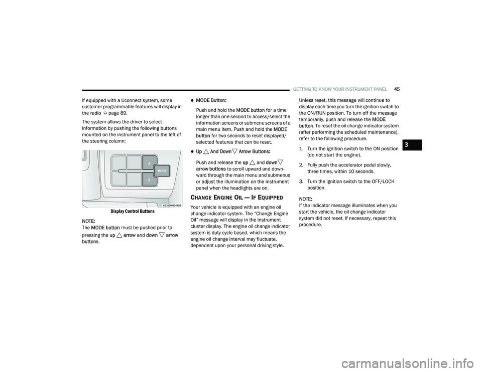
The system allows the driver to select
information by pushing the following buttons
mounted on the instrument panel to the left of
the steering column:
Display Control Buttons
NOTE:
The MODE button must be pushed prior to
pressing the up arrow and down arrow
buttons .MODE Button:
Push and hold the MODE button for a time
longer than one second to access/select the
information screens or submenu screens of a
main menu item. Push and hold the MODE
button for two seconds to reset displayed/
selected features that can be reset.
Up And Down Arrow Buttons:
Push and release the up and down
arrow buttons to scroll upward and down -
ward through the main menu and submenus
or adjust the illumination on the instrument
panel when the headlights are on.
CHANGE ENGINE OIL — IF EQUIPPED
Your vehicle is equipped with an engine oil
change indicator system. The “Change Engine
Oil” message will display in the instrument
cluster display. The engine oil change indicator
system is duty cycle based, which means the
engine oil change interval may fluctuate,
dependent upon your personal driving style. Unless reset, this message will continue to
display each time you turn the ignition switch to
the ON/RUN position. To turn off the message
temporarily, push and release the
MODE
button . To reset the oil change indicator system
(after performing the scheduled maintenance),
refer to the following procedure.
1. Turn the ignition switch to the ON position (do not start the engine).
2. Fully push the accelerator pedal slowly, three times, within 10 seconds.
3. Turn the ignition switch to the OFF/LOCK position.
NOTE:
If the indicator message illuminates when you
start the vehicle, the oil change indicator
system did not reset. If necessary, repeat this
procedure.
3
21_VF_OM_EN_USC_t.book Page 45