ignition RAM PROMASTER 2021 Workshop Manual
[x] Cancel search | Manufacturer: RAM, Model Year: 2021, Model line: PROMASTER, Model: RAM PROMASTER 2021Pages: 288, PDF Size: 15.22 MB
Page 202 of 288

200IN CASE OF EMERGENCY
SEALING A TIRE WITH TIRE SERVICE KIT
(A) Whenever You Stop To Use Tire Service
Kit:
1. Pull over to a safe location and turn on the
vehicle’s Hazard Warning Flashers.
2. Verify that the valve stem (on the wheel with the deflated tire) is in a position that is near
to the ground. This will allow the Tire Service
Kit Hoses (3) and (5) to reach the valve
stem and keep the Tire Service Kit flat on
the ground. This will provide the best
positioning of the kit when injecting the
sealant into the deflated tire and running
the air pump. Move the vehicle as
necessary to place the valve stem in this
position before proceeding.
3. Place the transmission in PARK (P) (auto transmission) or in Gear (manual
transmission) and place the ignition in the
OFF position.
4. Apply the parking brake.
(B) Setting Up To Use Tire Service Kit:
1. Push in the Mode Select Knob (2) and turn to the Sealant Mode position.
2. Uncoil the Sealant Hose (3) and then remove the cap from the fitting at the end of
the hose.
3. Place the Tire Service Kit flat on the ground next to the deflated tire.
4. Remove the cap from the valve stem and then screw the fitting at the end of the
Sealant Hose (3) onto the valve stem.
5. Uncoil the Power Plug (7) and insert the plug into the vehicle’s 12 Volt power outlet.
NOTE:
Do not remove foreign objects (e.g., screws or
nails) from the tire.
(C) Injecting Tire Service Kit Sealant Into
The Deflated Tire:
Always start the engine before turning ON the
Tire Service Kit.
NOTE:
Manual transmission vehicles must have the
parking brake engaged and the gear selector in
NEUTRAL.
After pushing the Power Button (1), the
sealant (white fluid) will flow from the Sealant
Bottle (4) through the Sealant Hose (3) and
into the tire.
NOTE:
Sealant may leak out through the puncture in
the tire.
If the sealant (white fluid) does not flow within
0 – 10 seconds through the Sealant Hose (3):
1. Push the Power Button (1) to turn Off the Tire Service Kit. Disconnect the Sealant
Hose (3) from the valve stem. Make sure
the valve stem is free of debris. Reconnect
the Sealant Hose (3) to the valve stem.
21_VF_OM_EN_USC_t.book Page 200
Page 205 of 288

IN CASE OF EMERGENCY203
(Continued)
5. Position the new Sealant Bottle (4) in the housing so that the Sealant Hose (3) aligns
with the hose slot in the front of the
housing. Push and hold the Sealant Bottle
release button, then push the bottle into the
housing by holding the button. An audible
click will be heard indicating the bottle is
locked into place. Release the button.
6. Verify that the cap is installed on the fitting at the end of the Sealant Hose (3) and
return the hose to its storage area (located
on top of the housing).
7. Return the Tire Service Kit to its storage location in the vehicle.
JUMP STARTING
If your vehicle has a discharged battery, it can
be jump started using a set of jumper cables
and a battery in another vehicle or by using a
portable battery booster pack. Jump starting
can be dangerous if done improperly, so please
follow the procedures in this section carefully. NOTE:
When using a portable battery booster pack,
follow the manufacturer’s operating instruc
-
tions and precautions.
PREPARATIONS FOR JUMP START
The vehicle’s jump starting remote posts are
located under the hood, in the engine
compartment on the driver's side.
The Remote Positive (+) Post is covered with a
protective cap located on the side of the Front
Power Distribution Center. The Remote Negative
(-) Post is located on the
core support closest to the front of the vehicle.
Jump Starting Locations
WARNING!
Do not attempt jump starting if the battery is
frozen. It could rupture or explode and cause
personal injury.
CAUTION!
Do not use a portable battery booster pack or
any other booster source with a system
voltage greater than 12 Volts or damage to
the battery, starter motor, alternator or
electrical system may occur.(+) Remote Positive Post
(-) Remote Negative Post
WARNING!
Take care to avoid the radiator cooling fan
whenever the hood is raised. It can start
anytime the ignition switch is ON. You can
be injured by moving fan blades.
Remove any metal jewelry such as rings,
watch bands and bracelets that could
make an inadvertent electrical contact. You
could be seriously injured.
7
21_VF_OM_EN_USC_t.book Page 203
Page 206 of 288

204IN CASE OF EMERGENCY
See below steps to prepare for jump starting:
1. Apply the parking brake, shift the
automatic transmission into PARK (P) and
turn the ignition to the OFF position.
2. Turn off the heater, radio, and all electrical accessories.
3. Pull upward and remove the protective cover over the remote positive (+) battery
post.
4. If using another vehicle to jump start the battery, park the vehicle within the jumper
cables reach, apply the parking brake and
make sure the ignition is OFF.
JUMP STARTING PROCEDURE
Connecting The Jumper Cables
Jumper Cable Connections
1. Connect the positive
(+) end of the jumper
cable to the remote positive (+)
post of the
discharged vehicle.
NOTE:
The remote positive (+) post is located in the
engine compartment on the driver's side under
the cover of the Front Power Distribution Center.
Batteries contain sulfuric acid that can
burn your skin or eyes and generate
hydrogen gas which is flammable and
explosive. Keep open flames or sparks
away from the battery.
WARNING! (Continued)WARNING!
Do not allow vehicles to touch each other as
this could establish a ground connection and
personal injury could result.
WARNING!
Failure to follow this jump starting procedure
could result in personal injury or property
damage due to battery explosion.
CAUTION!
Failure to follow these procedures could
result in damage to the charging system of
the booster vehicle or the discharged vehicle.
21_VF_OM_EN_USC_t.book Page 204
Page 211 of 288

IN CASE OF EMERGENCY209
TOWING A DISABLED VEHICLE
This section describes procedures for towing a disabled vehicle using a commercial towing service.
Proper towing or lifting equipment is required to
prevent damage to your vehicle. Use only tow
bars and other equipment designed for this
purpose, following equipment manufacturer’s
instructions. Use of safety chains is mandatory.
Attach a tow bar or other towing device to main
structural members of the vehicle, not to
fascia/bumper or associated brackets. State
and local laws regarding vehicles under tow
must be observed. If you must use the accessories (wipers,
defrosters, etc.) while being towed, the ignition
must be in the ON/RUN mode.
If the key fob is unavailable or the vehicle's
battery is discharged, for instructions on
shifting the automatic transmission out of
PARK (P) for towing Ú
page 207.
Towing Condition Wheels OFF The Ground
ALL Models
Flat Tow NONEIf transmission is operable:
• Transmission in NEUTRAL
• 25 mph (40 km/h) max speed
• 15 miles (24 km) max distance
Wheel Lift Or Dolly Tow Rear
Front OK
Flatbed ALL BEST METHOD
CAUTION!
Do not use sling type equipment when
towing. Vehicle damage may occur.
When securing the vehicle to a flat bed
truck, do not attach to front or rear suspen-
sion components. Damage to your vehicle
may result from improper towing.7
21_VF_OM_EN_USC_t.book Page 209
Page 222 of 288

220SERVICING AND MAINTENANCE
Refrigerant Recovery And Recycling
R-134a Air Conditioning Refrigerant is a
hydrofluorocarbon (HFC) that is an
ozone-saving product. However, FCA
recommends that air conditioning service be
performed by authorized dealer or other service
facilities using recovery and recycling
equipment.
NOTE:
Use only FCA approved A/C system PAG
compressor oil and refrigerants.
Cabin Air Filter (A/C Air Filter)
Refer to the Maintenance Plan in this chapter
for the proper maintenance intervals
Úpage 212. The cabin air filter is located in the fresh air inlet
in the engine compartment. Perform the
following procedure to replace the filter:
1. Remove the two screws that secure the
filter retainer to the fresh air inlet, and
remove the filter retainer.
Accessing Air Filter
2. Remove and replace the cabin air filter from the filter retainer.
Removing Air Filter
3. Install the cabin air filter/filter retainer back into the fresh air inlet. When installing the
filter retainer make sure the retainer is fully
engaged.
4. Install the two screws back into the assembly to secure the filter retainer to the
fresh air inlet.
WARNING!
Do not remove the cabin air filter while the
vehicle is running, or while the ignition is in
the ACC or ON/RUN mode. With the cabin air
filter removed and the blower operating, the
blower can contact hands and may propel dirt
and debris into your eyes, resulting in
personal injury.
1 — Screw Locations
2 — Fresh Air Inlet
1 — Fresh Air Inlet
2 — A/C Air Filter
3 — A/C Air Filter Retainer
21_VF_OM_EN_USC_t.book Page 220
Page 224 of 288

222SERVICING AND MAINTENANCE
(Continued)
Under normal operating conditions, the
catalytic converter will not require
maintenance. However, it is important to keep
the engine properly tuned to ensure proper
catalyst operation and prevent possible catalyst
damage.
NOTE:
Intentional tampering with emissions control
systems can result in civil penalties being
assessed against you. In unusual situations involving grossly
malfunctioning engine operation, a scorching
odor may suggest severe and abnormal catalyst
overheating. If this occurs, stop the vehicle, turn
off the engine and allow it to cool. Service,
including a tune-up to manufacturer's
specifications, should be obtained immediately.
To minimize the possibility of catalytic converter
damage:
Do not interrupt the ignition when the trans
-
mission is in gear and the vehicle is in
motion.
Do not try to start the vehicle by pushing or
towing the vehicle.
Do not idle the engine with any ignition
components disconnected or removed, such
as when diagnostic testing, or for prolonged
periods during very rough idle or malfunc -
tioning operating conditions.
WARNING!
Exhaust gases can injure or kill. They
contain carbon monoxide (CO), which is
colorless and odorless. Breathing it can
make you unconscious and can eventually
poison you Ú page 189.
A hot exhaust system can start a fire if you
park over materials that can burn, such as
grass or leaves, and those materials that
come into contact with your exhaust
system. Do not park or operate your vehicle
in areas where your exhaust system can
contact anything that can burn.
CAUTION!
The catalytic converter requires the use of
unleaded fuel only. Leaded gasoline will
destroy the effectiveness of the catalyst as
an emissions control device and may seri -
ously reduce engine performance and
cause serious damage to the engine.
Damage to the catalytic converter can
result if your vehicle is not kept in proper
operating condition. In the event of engine
malfunction, particularly involving engine
misfire or other apparent loss of perfor -
mance, have your vehicle serviced
promptly. Continued operation of your
vehicle with a severe malfunction could
cause the converter to overheat, resulting
in possible damage to the converter and
vehicle.
CAUTION! (Continued)
21_VF_OM_EN_USC_t.book Page 222
Page 225 of 288

SERVICING AND MAINTENANCE223
COOLING SYSTEM Coolant Checks
Check the engine coolant (antifreeze)
protection every 12 months (before the onset of
freezing weather, where applicable). If the
engine coolant is dirty, the system should be
drained, flushed, and refilled with fresh OAT
coolant (conforming to MS-12106) only by an
authorized dealer. Check the front of the A/C
condenser for any accumulation of bugs,
leaves, etc. If dirty, clean by gently spraying
water from a garden hose vertically down the
face of the condenser.
Cooling System — Drain, Flush And Refill
NOTE:
Some vehicles require special tools to add
coolant properly. Failure to fill these systems
properly could lead to severe internal engine
damage. If any coolant is needed to be added to
the system please contact an authorized dealer.
If the engine coolant (antifreeze) is dirty or
contains visible sediment, have an authorized
dealer clean and flush with OAT coolant
(conforming to MS.90032).
For the proper maintenance intervals
Úpage 212.
Selection Of Coolant
For further information Ú page 268.
NOTE:
Mixing of engine coolant (antifreeze) other
than specified Organic Additive Technology
(OAT) engine coolant, may result in engine
damage and may decrease corrosion protec-
tion. OAT engine coolant is different and
should not be mixed with Hybrid Organic
Additive Technology (HOAT) engine coolant or
any “globally compatible” coolant. If a
non-OAT engine coolant is introduced into the
cooling system in an emergency, the cooling
system will need to be drained, flushed, and
refilled with fresh OAT coolant (conforming to
MS.90032), by an authorized dealer as soon
as possible.
Do not use water alone or alcohol-based
engine coolant products. Do not use addi-
tional rust inhibitors or antirust products, as
they may not be compatible with the radiator
engine coolant and may plug the radiator.
WARNING!
You or others can be badly burned by hot
engine coolant (antifreeze) or steam from
your radiator. If you see or hear steam
coming from under the hood, do not open
the hood until the radiator has had time to
cool. Never open a cooling system pressure
cap when the radiator or coolant bottle is
hot.
Keep hands, tools, clothing, and jewelry
away from the radiator cooling fan when
the hood is raised. The fan starts automati -
cally and may start at any time, whether the
engine is running or not.
When working near the radiator cooling fan,
disconnect the fan motor lead and turn the
ignition to the OFF mode. The fan is
temperature controlled and can start at any
time the ignition is in the ON mode.
8
21_VF_OM_EN_USC_t.book Page 223
Page 230 of 288

228SERVICING AND MAINTENANCE
FUSES
General Information
The fuses protect electrical systems against
excessive current.
When a device does not work, you must check
the fuse element inside the blade fuse for a
break/melt.
Also, please be aware that when using power
outlets for extended periods of time with the
engine off may result in vehicle battery
discharge.
Blade Fuses
WARNING!
When replacing a blown fuse, always use
an appropriate replacement fuse with the
same amp rating as the original fuse. Never
replace a fuse with another fuse of higher
amp rating. Never replace a blown fuse with
metal wires or any other material. Do not
place a fuse inside a circuit breaker cavity
or vice versa. Failure to use proper fuses
may result in serious personal injury, fire
and/or property damage.
Before replacing a fuse, make sure that the
ignition is off and that all the other services
are switched off and/or disengaged.
If the replaced fuse blows again, contact an
authorized dealer.
If a general protection fuse for safety
systems (air bag system, braking system),
power unit systems (engine system, trans
-
mission system) or steering system blows,
contact an authorized dealer.
CAUTION!
If it is necessary to wash the engine
compartment, take care not to directly hit the
fuse box, and the windshield wiper motors
with water.
1 — Fuse Element
2 — Blade Fuse with a good/functional
fuse element
3 — Blade fuse with a bad/not functional
fuse element (blown fuse)
21_VF_OM_EN_USC_t.book Page 228
Page 232 of 288

230SERVICING AND MAINTENANCE
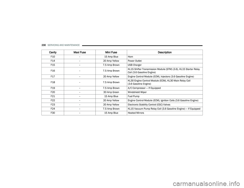
F10–15 Amp Blue Horn
F14 –20 Amp Yellow Power Outlet
F15 –7.5 Amp Brown USB Charger
F16 –7.5 Amp Brown KL15 Shifter Transmission Module (STM) (3.6), KL15 Starter Relay
Coil (3.6 Gasoline Engine)
F17 –20 Amp Yellow Engine Control Module (ECM), Injectors (3.6 Gasoline Engine)
F18 –7.5 Amp Brown KL30 Engine Control Module (ECM), KL30 Main Relay Coil
(3.6 Gasoline Engine)
F19 –7.5 Amp Brown A/C Compressor — If Equipped
F20 –30 Amp Green Windshield Wiper
F21 –15 Amp Blue Fuel Pump
F22 –20 Amp Yellow Engine Control Module (ECM), Ignition Coils (3.6 Gasoline Engine)
F23 –20 Amp Yellow Electronic Stability Control (ESC) Valves
F24 –7.5 Amp Brown KL15 Vacuum Pump Relay Coil (3.6 Gasoline Engine) — If Equipped
F30 –15 Amp Blue Heated Mirrors
CavityMaxi Fuse Mini Fuse Description
21_VF_OM_EN_USC_t.book Page 230
Page 236 of 288

234SERVICING AND MAINTENANCE
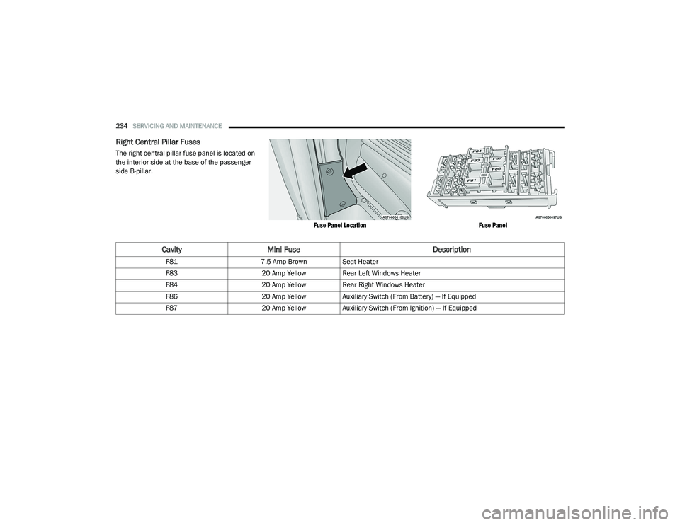
Right Central Pillar Fuses
The right central pillar fuse panel is located on
the interior side at the base of the passenger
side B-pillar.
Fuse Panel LocationFuse Panel
CavityMini Fuse Description
F817.5 Amp Brown Seat Heater
F83 20 Amp YellowRear Left Windows Heater
F84 20 Amp YellowRear Right Windows Heater
F86 20 Amp YellowAuxiliary Switch (From Battery) — If Equipped
F87 20 Amp YellowAuxiliary Switch (From Ignition) — If Equipped
21_VF_OM_EN_USC_t.book Page 234