clock RAM PROMASTER 2021 Owners Manual
[x] Cancel search | Manufacturer: RAM, Model Year: 2021, Model line: PROMASTER, Model: RAM PROMASTER 2021Pages: 288, PDF Size: 15.22 MB
Page 35 of 288

GETTING TO KNOW YOUR VEHICLE33
Temperature Control
Temperature Control regulates the temperature
of the air forced through the climate system.
The temperature increases as you
turn the temperature control knob
clockwise.
The temperature decreases as you
turn the temperature control knob
counterclockwise.
Blower Control
Blower Control regulates the amount
of air forced through the climate
system. There are seven blower
speeds available. The blower speed
increases as you turn the blower control knob
clockwise from the lowest blower setting. The
blower speed decreases as you turn the blower
control knob counterclockwise.
NOTE:
Depending on the configuration, your vehicle
may be equipped with four blower speeds.
Mode Control
Turn the mode control knob to change
the airflow distribution mode. The
airflow distribution mode can be
adjusted so air comes from the
instrument panel outlets, floor outlets, defrost
outlets and demist outlets.
Panel Mode
Air comes from the outlets in the
instrument panel. Each of these
outlets can be individually adjusted to
direct the flow of air. The air vanes of
the center outlets and outboard outlets can be
moved up and down or side to side to regulate
airflow direction. There is a shut off wheel
located below the air vents to shut off or adjust
the amount of airflow from these outlets.
Bi-Level Mode
Air comes from the instrument panel
outlets and floor outlets. A slight
amount of air is directed through
the defrost and side window
demister outlets.
NOTE:
Bi-Level mode is designed under comfort condi
-
tions to provide cooler air out of the panel
outlets and warmer air from the floor outlets.
Floor Mode
Air comes from the floor outlets.
A slight amount of air is directed
through the defrost and side window
demister outlets.
Mix Mode
Air is directed through the floor,
defrost, and side window demister
outlets. This setting works best in cold
or snowy conditions that require extra
heat to the windshield. This setting is good for
maintaining comfort while reducing moisture on
the windshield.
Climate Control OFF
To turn the Climate Controls off, turn
the blower control knob to the OFF (O)
position.
2
21_VF_OM_EN_USC_t.book Page 33
Page 94 of 288

92MULTIMEDIA
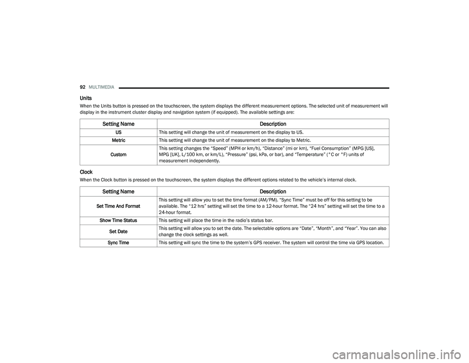
Units
When the Units button is pressed on the touchscreen, the system displays the different measurement options. The selected unit of measurement will
display in the instrument cluster display and navigation system (if equipped). The available settings are:
Clock
When the Clock button is pressed on the touchscreen, the system displays the different options related to the vehicle’s internal clock.
Setting Name Description
USThis setting will change the unit of measurement on the display to US.
Metric This setting will change the unit of measurement on the display to Metric.
Custom This setting changes the “Speed” (MPH or km/h), “Distance” (mi or km), “Fuel Consumption” (MPG [US],
MPG [UK], L/100 km, or km/L), “Pressure” (psi, kPa, or bar), and “Temperature” (°C or °F) units of
measurement independently.
Setting Name
Description
Set Time And FormatThis setting will allow you to set the time format (AM/PM). “Sync Time” must be off for this setting to be
available. The “12 hrs” setting will set the time to a 12-hour format. The “24 hrs” setting will set the time to a
24-hour format.
Show Time Status This setting will place the time in the radio’s status bar.
Set Date This setting will allow you to set the date. The selectable options are “Date”, “Month”, and “Year”. You can also
change the clock settings as well.
Sync Time This setting will sync the time to the system’s GPS receiver. The system will control the time via GPS location.
21_VF_OM_EN_USC_t.book Page 92
Page 101 of 288

MULTIMEDIA99
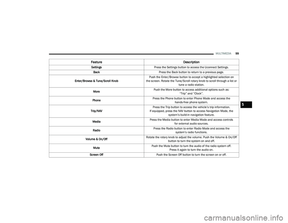
Feature Description
SettingsPress the Settings button to access the Uconnect Settings.
Back Press the Back button to return to a previous page.
Enter/Browse & Tune/Scroll Knob Push the Enter/Browse button to accept a highlighted selection on
the screen. Rotate the Tune/Scroll rotary knob to scroll through a list or tune a radio station.
More Push the More button to access additional options such as:
“Trip” and “Clock”.
Phone Press the Phone button to enter Phone Mode and access the
hands-free phone system.
Trip/NAV Press the Trip button to access the vehicle’s trip information.
If equipped, press the NAV button to access Navigation Mode, the system’s build-in navigation feature.
Media Press the Media button to enter Media Mode and access controls
for external audio sources.
Radio Press the Radio button to enter Radio Mode and access the
system’s radio functions.
Volume & On/Off Rotate the rotary knob to adjust the volume. Push the Volume & On/Off
button to turn the system on and off.
Mute Push the Mute button to turn the audio of the radio system off.
Press it again to turn the audio on.
Screen Off Push the Screen Off button to turn the screen on or off.
5
21_VF_OM_EN_USC_t.book Page 99
Page 103 of 288

MULTIMEDIA101
UCONNECT MODES
RADIO MODE
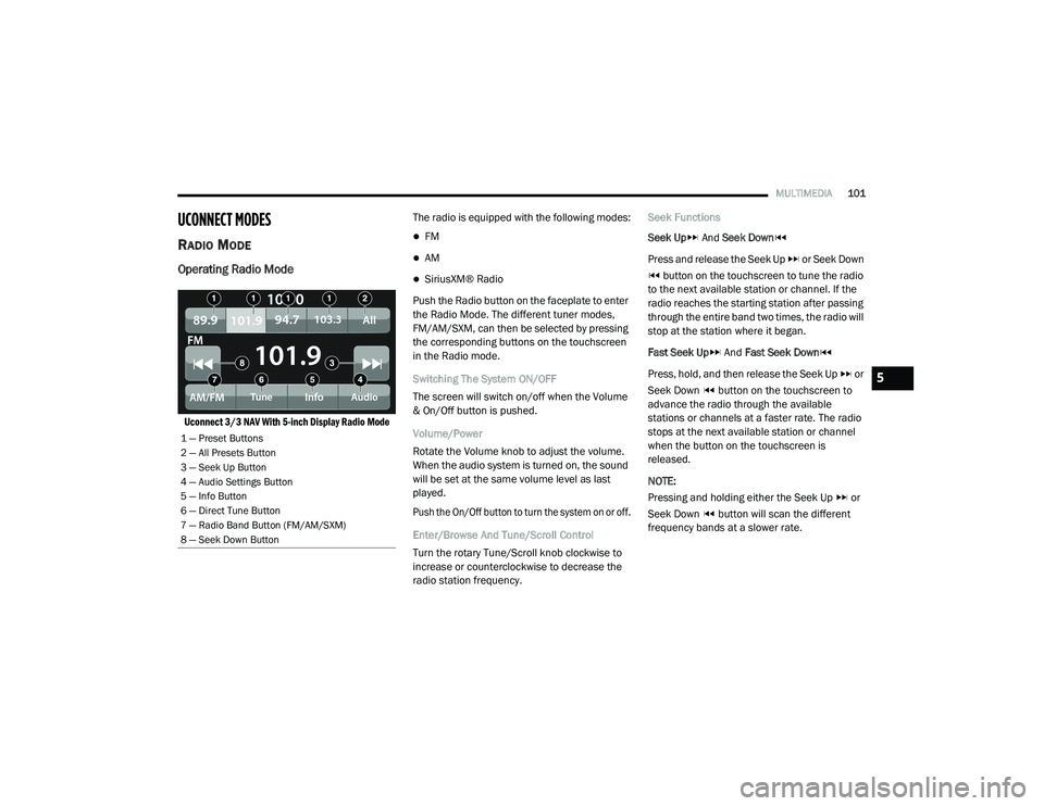
Operating Radio Mode
Uconnect 3/3 NAV With 5-inch Display Radio Mode
The radio is equipped with the following modes:
FM
AM
SiriusXM® Radio
Push the Radio button on the faceplate to enter
the Radio Mode. The different tuner modes,
FM/AM/SXM, can then be selected by pressing
the corresponding buttons on the touchscreen
in the Radio mode.
Switching The System ON/OFF
The screen will switch on/off when the Volume
& On/Off button is pushed.
Volume/Power
Rotate the Volume knob to adjust the volume.
When the audio system is turned on, the sound
will be set at the same volume level as last
played.
Push the On/Off button to turn the system on or off.
Enter/Browse And Tune/Scroll Control
Turn the rotary Tune/Scroll knob clockwise to
increase or counterclockwise to decrease the
radio station frequency. Seek Functions
Seek Up
And Seek Down
Press and release the Seek Up or Seek Down button on the touchscreen to tune the radio
to the next available station or channel. If the
radio reaches the starting station after passing
through the entire band two times, the radio will
stop at the station where it began.
Fast Seek Up And Fast Seek Down
Press, hold, and then release the Seek Up or
Seek Down button on the touchscreen to
advance the radio through the available
stations or channels at a faster rate. The radio
stops at the next available station or channel
when the button on the touchscreen is
released.
NOTE:
Pressing and holding either the Seek Up or
Seek Down button will scan the different
frequency bands at a slower rate.
1 — Preset Buttons
2 — All Presets Button
3 — Seek Up Button
4 — Audio Settings Button
5 — Info Button
6 — Direct Tune Button
7 — Radio Band Button (FM/AM/SXM)
8 — Seek Down Button
5
21_VF_OM_EN_USC_t.book Page 101
Page 194 of 288

192IN CASE OF EMERGENCY
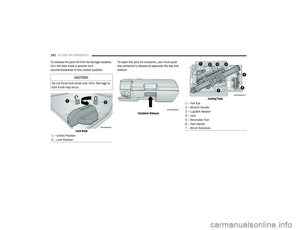
To release the jack kit from its storage location,
turn the lock knob a quarter turn
counterclockwise to the unlock position.
Lock Knob
To open the jack kit container, you must push
the container’s release to separate the top and
bottom.
Container Release Jacking Tools
CAUTION!
Do not force lock knob over limit. Damage to
lock knob may occur.
1 — Unlock Position
2 — Lock Position
1 — Tow Eye
2 — Wrench Handle
3 — Lug Bolt Adapter
4 — Jack
5 — Reversible Tool
6 — Tool Handle
7 — Winch Extension
21_VF_OM_EN_USC_t.book Page 192
Page 195 of 288

IN CASE OF EMERGENCY193
SPARE TIRE REMOVAL
1. Remove the spare tire before attempting to
jack up the vehicle. Attach the lug bolt
adapter to the winch extension and insert
it into the winch mechanism.
Jack Tools Winch Location
The winch mechanism is located under the
rear of the vehicle to the right of the spare tire.
Winch Extension
2. Rotate the wheel wrench handle counter -
clockwise until the spare tire is on the
ground with enough cable slack to allow you
to pull it out from under the vehicle. NOTE:
The winch mechanism is designed for use with
the winch extension tube only. Use of an air
wrench or other power tools is not recom-
mended and can damage the winch.
Lowering Spare Tire
3. Pull the spare tire out from under the vehicle to gain access to the spare tire
retainer.
1 — Wrench Handle
2 — Lug Bolt Adapter
3 — Winch Extension7
21_VF_OM_EN_USC_t.book Page 193
Page 197 of 288

IN CASE OF EMERGENCY195
Jack Warning Label
Assembled Jack
1. Loosen (but do not remove) the wheel lug
bolts by turning them counterclockwise
one turn while the wheel is still on the
ground.
2. There are two jack engagement locations on each side of the vehicle body.
Jacking Engagement Locations
NOTE:
The rear jacking location is located in front of
the rear tire and in front of the leaf spring
mount.
Front Lifting Point
Front Jacking Location
CAUTION!
Do not attempt to raise the vehicle by jacking
on locations other than those indicated in the
Jacking Instructions for this vehicle.
CAUTION!
Do not attempt to raise the vehicle by jacking
on locations other than those indicated.
7
21_VF_OM_EN_USC_t.book Page 195
Page 198 of 288

196IN CASE OF EMERGENCY
Rear Lifting Point
Rear Jacking Location
NOTE:
The front jacking location is located behind the
front tire and in front of the driver/passenger
door. 3. Place the wrench handle and lug bolt
adapter on the jack screw and turn
clockwise until the jack head is properly
engaged in the described location. Do not
raise the vehicle until you are sure the jack
is securely engaged.
4. Raise the vehicle by turning the jack screw clockwise, using the wrench handle and lug
bolt adapter. Raise the vehicle only until the
tire just clears the surface and enough
clearance is obtained to install the spare
tire. Minimum tire lift provides maximum
stability. 5. Remove the wheel lug bolts. For vehicles
with wheel covers, remove the cover from
the wheel by hand. Do not pry the wheel
cover off. Then pull the wheel off the hub.
6. Install the spare tire. Lightly tighten the wheel lug bolts.
Mounting Spare Tire
WARNING!
Being under a jacked-up vehicle is
dangerous. The vehicle could slip off the jack
and fall on you. You could be crushed. Never
get any part of your body under a vehicle that
is on a jack. If you need to get under a raised
vehicle, take it to a service center where it
can be raised on a lift.
WARNING!
Raising the vehicle higher than necessary can
make the vehicle less stable. It could slip off
the jack and hurt someone near it. Raise the
vehicle only enough to remove the tire.
21_VF_OM_EN_USC_t.book Page 196
Page 199 of 288

IN CASE OF EMERGENCY197
NOTE:
Do not install the wheel cover on the spare tire.
7. Lower the vehicle by turning the jack screw
left Ú page 264.
8. Lower the jack to its fully-closed position.
9. Stow the damaged wheel/spare tire with the cable and wheel spacer before driving
the vehicle. 10. Install the winch extension and
rotate the
wrench handle clockwise until the winch
mechanism operator hears “3 clicks” from
the device to indicate the wheel is properly
stowed under the vehicle.
11. Stow the jack, jack handle and winch handle tools back in the storage
compartment.
12. Check the spare tire pressure as soon as possible. Correct the tire pressure, as
required.
For vehicles with aluminum wheels:
The center cap must be pushed out from the
rear to install the retainer and stow the tire.
WHEEL COVERS
The wheel covers on the vehicle are held in
place by the wheel lug bolts and can be
removed after the wheel lug bolts are taken off.
TIRE SERVICE KIT — IF EQUIPPED
Small punctures up to 1/4 inch (6 mm) in the
tire tread can be sealed with Tire Service Kit.
Foreign objects (e.g., screws or nails) should not
be removed from the tire. Tire Service Kit can be
used in outside temperatures down to
approximately -4°F (-20°C).
This kit will provide a temporary tire seal,
allowing you to drive your vehicle up to
100 miles (160 km) with a maximum speed of 50 mph (80 km/h).
WARNING!
To avoid the risk of forcing the vehicle off the
jack, do not tighten the wheel nuts fully until
the vehicle has been lowered. Failure to
follow this warning may result in serious
injury.
CAUTION!
Be sure to mount the spare tire with the valve
stem facing outward. The vehicle could be
damaged if the spare tire is mounted
incorrectly.WARNING!
A loose tire or jack thrown forward in a
collision or hard stop could endanger the
occupants of the vehicle. Always stow the jack
parts and the spare tire in the places
provided. Have the deflated (flat) tire repaired
or replaced immediately.
CAUTION!
Use a back-and-forth motion to remove the
hub cap. Do not use a twisting motion when
removing the hub cap, damage to the hub
cap finish may occur.
7
21_VF_OM_EN_USC_t.book Page 197
Page 239 of 288

SERVICING AND MAINTENANCE237
Front Turn Signal/Parking Lamps
See below steps to replace:
1. Remove one retaining screw on the lower
headlamp filler panel. Remove filler panel.
2. Remove two retaining screws on the upper headlamp filler panel. Remove filler panel.
3. Remove one upper retaining screw from the headlamp housing.
4. Remove two lower retaining screws from the headlamp housing.
5. Pull Headlamp forward, disconnect the harness electrical connector and remove
the headlamp assembly from vehicle.
6. Rotate the bulb counterclockwise and remove.
7. Install the bulb into socket, and rotate bulb/ socket clockwise into lamp locking it in
place.
8. Carefully reinstall headlamp in the same position on the vehicle, so as not to affect
headlamp aiming.
9. Install the one upper retaining screw on headlamp housing. 10. Install the two lower retaining screws on
headlamp housing.
11. Carefully reinstall the lower headlamp filler panel and one retaining screw.
12. Carefully reinstall the upper headlamp filler panel and two retaining screws.
Daytime Running Lamp (DRL)/Front Side
Marker Lamp
See below steps to replace:
1. Remove one retaining screw on the lower headlamp filler panel. Remove filler panel.
2. Remove two retaining screws on the upper headlamp filler panel. Remove filler panel.
3. Remove one upper retaining screw from the headlamp housing.
4. Remove two lower retaining screws from the headlamp housing.
5. Pull Headlamp forward, disconnect the harness electrical connector and remove
the headlamp assembly from vehicle.
6. Remove the (DRL), side marker bulb by pulling straight out. 7. Replace lamp as required and lock in place.
8. Reinstall plastic cap.
9. Carefully reinstall headlamp in the same
position on the vehicle, as not to affect
headlamp aiming.
10. Install the one upper retaining screw on the headlamp housing.
11. Install the two lower retaining screws on the headlamp housing.
12. Carefully reinstall the lower headlamp filler panel and one retaining screw.
13. Carefully reinstall the upper headlamp filler panel and two retaining screws.
Front Fog Lamps
See below steps to replace:
1. Turn front wheels inboard to access cover in wheel liner.
2. Open the cover on the front of the wheel liner.
3. Remove connection and replace the bulb.
8
21_VF_OM_EN_USC_t.book Page 237