warning lights RAM PROMASTER 2021 Owners Manual
[x] Cancel search | Manufacturer: RAM, Model Year: 2021, Model line: PROMASTER, Model: RAM PROMASTER 2021Pages: 288, PDF Size: 15.22 MB
Page 4 of 288
2
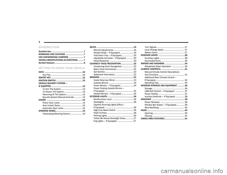
INTRODUCTION
Symbols Key ............................................................ 7
WARNINGS AND CAUTIONS ................................. 7
VAN CONVERSIONS/CAMPERS ........................... 7
VEHICLE MODIFICATIONS/ALTERATIONS ........... 7
Symbol Glossary ..................................................... 8
GETTING TO KNOW YOUR VEHICLE
KEYS ......................................................................10
Key Fob......................................................... 10
SENTRY KEY ..........................................................12
IGNITION SWITCH .................................................12
VEHICLE SECURITY SYSTEM —
IF EQUIPPED .........................................................13
To Arm The System ...................................... 13
To Disarm The System................................. 13
Rearming Of The System............................. 13
Security System Manual Override .............. 13
DOORS ..................................................................14
Power Door Locks ....................................... 14
Auto Unlock Doors ....................................... 15
Automatic Door Locks ................................. 15
STEERING WHEEL.................................................15
Telescoping Steering Column ..................... 15 SEATS .................................................................... 15
Manual Adjustments ................................... 16
Heated Seats — If Equipped ....................... 19
Fold Down Tray — If Equipped..................... 20
Adjustable Armrests — If Equipped ............ 20
Head Restraints .......................................... 20
UCONNECT VOICE RECOGNITION ....................... 22
Introducing Voice Recognition .................... 22
Basic Voice Commands............................... 22
Get Started ................................................... 22
Additional Information ................................. 22
MIRRORS ............................................................. 23
Inside Rearview Mirror ................................ 23
Outside Mirrors ........................................... 24
Power Mirrors — If Equipped ....................... 24
Power Folding Outside Mirrors —
If Equipped ................................................... 25 Heated Mirrors — If Equipped ..................... 25
EXTERIOR LIGHTS ................................................ 26
Multifunction Lever ..................................... 26
Headlights ................................................... 26
Daytime Running Lights (DRLs) —
If Equipped .................................................. 26 High/Low Beam Switch .............................. 26
Flash-To-Pass .............................................. 26
Parking Lights ............................................. 26
Follow Me Home/Headlight Delay .............. 27
Fog Lights — If Equipped ............................ 27 Turn Signals ................................................. 27
Lane Change Assist ..................................... 27
Battery Saver ............................................... 27
INTERIOR LIGHTS ................................................28
Courtesy Lights ............................................ 28
Illuminated Entry ......................................... 30
WIPERS AND WASHERS .....................................30
Windshield Wiper Operation ...................... 30
CLIMATE CONTROLS ...........................................31
Manual Climate Control Descriptions
And Functions .............................................. 31 Additional Rear Climate Control —
If Equipped ................................................... 34 Operating Tips.............................................. 34
INTERIOR STORAGE AND EQUIPMENT ..............36
Storage ......................................................... 36
USB/AUX Control — If Equipped ................ 37
Power Outlets............................................... 37
Auxiliary Switches — If Equipped ................ 38
WINDOWS ............................................................39
Power Windows .......................................... 39
Window Bar Grates — If Equipped .............. 39
Wind Buffeting ............................................ 40
HOOD......................................................................40
Opening ........................................................ 40
Closing.......................................................... 41
CARGO AREA FEATURES .....................................41
21_VF_OM_EN_USC_t.book Page 2
Page 5 of 288
3
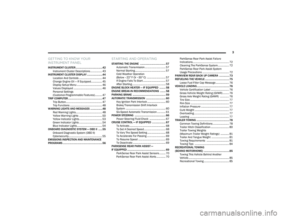
GETTING TO KNOW YOUR
INSTRUMENT PANEL
INSTRUMENT CLUSTER........................................42Instrument Cluster Descriptions ................. 43
INSTRUMENT CLUSTER DISPLAY .......................44
Location And Controls ................................. 44
Change Engine Oil — If Equipped................ 45
Display Setup Menu .................................... 46
Values Displayed ......................................... 46
Personal Settings
(Customer-Programmable Features) .......... 47
TRIP COMPUTER ...................................................47
Trip Button.................................................... 47
Trip Functions .............................................. 48
WARNING LIGHTS AND MESSAGES ..................48
Red Warning Lights...................................... 48
Yellow Warning Lights ................................. 50
Yellow Indicator Lights................................. 53
Green Indicator Lights ................................. 54
Blue Indicator Lights .................................... 54
ONBOARD DIAGNOSTIC SYSTEM — OBD II ......55
Onboard Diagnostic System (OBD II)
Cybersecurity................................................ 55
EMISSIONS INSPECTION AND MAINTENANCE
PROGRAMS ...........................................................56
STARTING AND OPERATING
STARTING THE ENGINE ...................................... 57
Automatic Transmission.............................. 57
Normal Starting............................................ 57
Cold Weather Operation
(Below –22°F Or −30°C) ........................... 57 If Engine Fails To Start ................................ 57
After Starting ................................................ 58
ENGINE BLOCK HEATER — IF EQUIPPED ......... 58
ENGINE BREAK-IN RECOMMENDATIONS ........ 58
PARKING BRAKE ................................................. 59
AUTOMATIC TRANSMISSION ............................. 60 Key Ignition Park Interlock .......................... 60
Brake/Transmission Shift Interlock
System ......................................................... 60 Six-Speed Automatic Transmission ............ 61
POWER STEERING .............................................. 66
Power Steering Fluid Check ....................... 67
CRUISE CONTROL — IF EQUIPPED .................... 67
To Activate.................................................... 68
To Set A Desired Speed............................... 68
To Vary The Speed Setting .......................... 68
To Accelerate For Passing ........................... 69
To Resume Speed ....................................... 69
To Deactivate ............................................... 69
PARKSENSE REAR PARK ASSIST —
IF EQUIPPED ......................................................... 69
ParkSense Rear Park Assist Sensors ......... 70
ParkSense Rear Park Assist Alerts ............. 70 ParkSense Rear Park Assist Failure
Indications.................................................... 72 Cleaning The ParkSense System................ 72
ParkSense Rear Park Assist System
Usage Precautions ...................................... 72
PARKVIEW REAR BACK UP CAMERA ...............73
REFUELING THE VEHICLE ....................................75
Loose Fuel Filler Cap Message................... 76
VEHICLE LOADING ................................................76
Vehicle Certification Label .......................... 76
Gross Vehicle Weight Rating (GVWR) ......... 76
Gross Axle Weight Rating (GAWR) ............. 76
Tire Size ........................................................ 77
Rim Size ....................................................... 77
Inflation Pressure ........................................ 77
Curb Weight ................................................. 77
Overloading .................................................. 77
Loading ........................................................ 77
TRAILER TOWING .................................................78
Common Towing Definitions ....................... 78
Trailer Hitch Classification .......................... 80
Trailer Towing Weights
(Maximum Trailer Weight Ratings) ............ 81 Trailer And Tongue Weight ......................... 81
Towing Requirements ................................ 81
Towing Tips ................................................. 84
RECREATIONAL TOWING
(BEHIND MOTORHOME) ......................................85
Towing This Vehicle Behind Another
Vehicle .......................................................... 85 Recreational Towing .................................... 85
21_VF_OM_EN_USC_t.book Page 3
Page 10 of 288
8
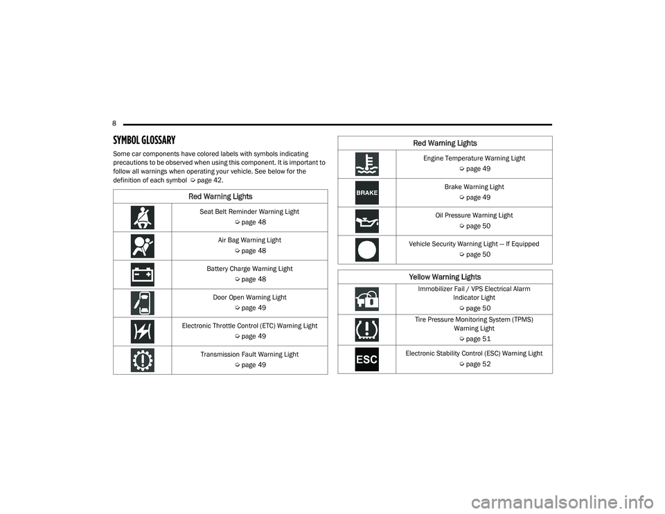
SYMBOL GLOSSARY
Some car components have colored labels with symbols indicating
precautions to be observed when using this component. It is important to
follow all warnings when operating your vehicle. See below for the
definition of each symbol Úpage 42.
Red Warning Lights
Seat Belt Reminder Warning Light
Úpage 48
Air Bag Warning Light Úpage 48
Battery Charge Warning Light Úpage 48
Door Open Warning Light Úpage 49
Electronic Throttle Control (ETC) Warning Light Úpage 49
Transmission Fault Warning Light Úpage 49
Engine Temperature Warning Light
Úpage 49
Brake Warning Light Úpage 49
Oil Pressure Warning Light Úpage 50
Vehicle Security Warning Light — If Equipped Úpage 50
Yellow Warning Lights
Immobilizer Fail / VPS Electrical Alarm
Indicator Light
Ú page 50
Tire Pressure Monitoring System (TPMS) Warning Light
Ú page 51
Electronic Stability Control (ESC) Warning Light Úpage 52
Red Warning Lights
21_VF_OM_EN_USC_t.book Page 8
Page 11 of 288
9
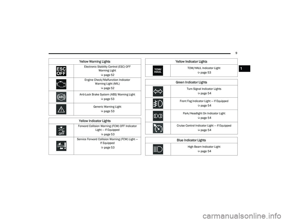
Electronic Stability Control (ESC) OFF Warning Light
Ú page 52
Engine Check/Malfunction Indicator Warning Light (MIL)
Úpage 52
Anti-Lock Brake System (ABS) Warning Light Úpage 53
Generic Warning Light Úpage 53
Yellow Indicator Lights
Forward Collision Warning (FCW) OFF Indicator
Light — If Equipped
Úpage 53
Service Forward Collision Warning (FCW) Light — If Equipped
Ú page 53
Yellow Warning Lights
TOW/HAUL Indicator Light Úpage 53
Green Indicator Lights
Turn Signal Indicator Lights
Úpage 54
Front Fog Indicator Light — If Equipped Úpage 54
Park/Headlight On Indicator Light Úpage 54
Cruise Control Indicator Light — If Equipped Úpage 54
Blue Indicator Lights
High Beam Indicator Light
Úpage 54
Yellow Indicator Lights
1
21_VF_OM_EN_USC_t.book Page 9
Page 15 of 288

GETTING TO KNOW YOUR VEHICLE13
NOTE:
Opening the driver's door when the key is in the
ignition and the ignition switch position is STOP
(OFF/LOCK) sounds a signal to remove the key.
VEHICLE SECURITY SYSTEM — IF EQUIPPED
The Vehicle Security system monitors the
vehicle doors and ignition for unauthorized
operation. When the Vehicle Security system is
activated, interior switches for door locks are
disabled. The system provides both audible and
visible signals. For the first three minutes, the
horn will sound, and the turn signal lights will
flash. For an additional 15 minutes, only the
turn signal lights will flash.
TO ARM THE SYSTEM
To arm the system, the Vehicle Security system
will set when you use the key fob to lock the
doors. If a door or the hood is not properly shut,
the system will not be armed.
TO DISARM THE SYSTEM
Use the key fob to unlock the door and disarm
the system.
The Vehicle Security system will also disarm if a
programmed Sentry Key is inserted into the
ignition switch. To exit the alarming mode,
push the key fob unlock button, or insert a
programmed Sentry Key into the ignition switch. The Vehicle Security system is designed to
protect your vehicle. However, you can create
conditions where the system will give you a false
alarm. If one of the previously described arming
sequences has occurred, the Vehicle Security
system will arm regardless of whether you are in
the vehicle or not. If you remain in the vehicle
and open a door, the alarm will sound. If this
occurs, disarm the Vehicle Security system.
REARMING OF THE SYSTEM
If the system has not been disabled, the Vehicle
Security system will rearm itself after the 15
additional minutes of turn lamps flashing. If the
condition which initiated the alarm is still
present, the system will ignore that condition
and monitor the remaining doors and ignition.
SECURITY SYSTEM MANUAL OVERRIDE
The Vehicle Security system will not arm/disarm
if you lock/unlock the doors using the manual
door lock.
Allowing children to be in a vehicle unat
-
tended is dangerous for a number of
reasons. A child or others could be seriously
or fatally injured. Children should be
warned not to touch the parking brake,
brake pedal or the gear selector.
Do not leave the key fob in or near the
vehicle, or in a location accessible to chil-
dren. A child could operate power windows,
other controls, or move the vehicle.
Do not leave children or animals inside
parked vehicles in hot weather. Interior
heat build-up may cause serious injury or
death.
CAUTION!
An unlocked vehicle is an invitation. Always
remove the key from the ignition and lock all
the doors when leaving the vehicle unattended.
WARNING! (Continued)
2
21_VF_OM_EN_USC_t.book Page 13
Page 40 of 288

38GETTING TO KNOW YOUR VEHICLE
(Continued)
NOTE:
Do not connect devices with power higher than
180 W to the socket. Do not damage the socket
by using unsuitable adapters.
Power Outlet Fuses — Under Hood
AUXILIARY SWITCHES — IF EQUIPPED
Your vehicle may be equipped with two auxiliary
switches located on the instrument panel to the
left of the steering column which can be used to
power various electronic devices. Connections
to the switches are found in the right central
pillar fuse panel at the base of the passenger
side B-pillar.
Auxiliary Upfitter Switches
Auxiliary Switch 1 is configured to constant
battery feed, while Auxiliary Switch 2 is
configured to ignition feed.
For further information on using the auxiliary
switches, please refer to the Ram Body Builders
Guide by accessing www.rambodybuilder.com
and choosing the appropriate links.
1 — F14 Fuse 20 Amp Yellow Front Power Outlet
2 — F09 Fuse 15 Amp Blue Rear Power Outlet
WARNING!
To avoid serious injury or death:
Only devices designed for use in this type of
outlet should be inserted into any 12 Volt
outlet.
Do not touch with wet hands.
Close the lid when not in use and while
driving the vehicle.
If this outlet is mishandled, it may cause an
electric shock and failure.
CAUTION!
Many accessories that can be plugged in
draw power from the vehicle's battery, even
when not in use (i.e., cellular phones, etc.).
Eventually, if plugged in long enough, the
vehicle's battery will discharge sufficiently
to degrade battery life and/or prevent the
engine from starting.
Accessories that draw higher power (i.e.,
coolers, vacuum cleaners, lights, etc.) will
degrade the battery even more quickly.
Only use these intermittently and with
greater caution.
After the use of high power draw accesso -
ries, or long periods of the vehicle not being
started (with accessories still plugged in),
the vehicle must be driven a sufficient
length of time to allow the generator to
recharge the vehicle's battery.
WARNING! (Continued)
21_VF_OM_EN_USC_t.book Page 38
Page 50 of 288
48GETTING TO KNOW YOUR INSTRUMENT PANEL
Start Of Trip Procedure
With the ignition on, push and hold the TRIP
button for over two seconds to reset trip
information.
Exit Trip
To exit the Trip function, push the TRIP button
until all the trip menu items have been
displayed and the display returns to the main
menu.
TRIP FUNCTIONS
Both trip functions are resettable (reset — start
of new trip).
Trip A/Trip B
Trip Distance
Average Fuel Consumption
Average Speed
Travel Time (Driving Time)
NOTE:
“Trip B” functions may be excluded (see “Trip B
Data”). “Range” and “Instantaneous Fuel
Consumption” cannot be reset.
WARNING LIGHTS AND MESSAGES
The warning/indicator lights will illuminate in the
instrument panel together with a dedicated
message and/or acoustic signal when applicable.
These indications are indicative and precautionary
and as such must not be considered as exhaustive
and/or alternative to the information contained in
the Owner’s Manual, which you are advised to read
carefully in all cases. Always refer to the
information in this chapter in the event of a failure
indication. All active telltales will display first if
applicable. The system check menu may appear
different based upon equipment options and
current vehicle status. Some telltales are optional
and may not appear.
RED WARNING LIGHTS
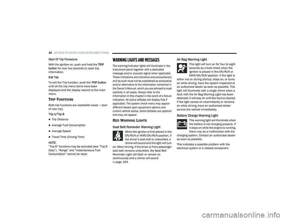
Seat Belt Reminder Warning Light
When the ignition is first placed in the
ON/RUN or MAR/ON/RUN position, if
the driver’s seat belt is unbuckled, a
chime will sound and the light will turn
on. When driving, if the driver or front passenger
seat belt remains unbuckled, the Seat Belt
Reminder Light will flash or remain on
continuously and a chime will sound
Ú page 164.
Air Bag Warning Light
This light will turn on for four to eight
seconds as a bulb check when the
ignition is placed in the ON/RUN or
MAR/ON/RUN position. If the light is
either not on during startup, stays on, or turns
on while driving, have the system inspected at
an authorized dealer as soon as possible. This
light will illuminate with a single chime when a
fault with the Air Bag Warning Light has been
detected, it will stay on until the fault is cleared.
If the light comes on intermittently or remains
on while driving, have an authorized dealer
service the vehicle immediately.
Battery Charge Warning Light
This warning light will illuminate when
the battery is not charging properly. If
it stays on while the engine is running,
there may be a malfunction with the
charging system. Contact an authorized dealer
as soon as possible.
This indicates a possible problem with the
electrical system or a related component.
21_VF_OM_EN_USC_t.book Page 48
Page 52 of 288
50GETTING TO KNOW YOUR INSTRUMENT PANEL
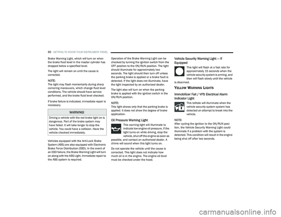
Brake Warning Light, which will turn on when
the brake fluid level in the master cylinder has
dropped below a specified level.
The light will remain on until the cause is
corrected.
NOTE:
The light may flash momentarily during sharp
cornering maneuvers, which change fluid level
conditions. The vehicle should have service
performed, and the brake fluid level checked.
If brake failure is indicated, immediate repair is
necessary.
Vehicles equipped with the Anti-Lock Brake
System (ABS) are also equipped with Electronic
Brake Force Distribution (EBD). In the event of
an EBD failure, the Brake Warning Light will turn
on along with the ABS Light. Immediate repair to
the ABS system is required. Operation of the Brake Warning Light can be
checked by turning the ignition switch from the
OFF position to the ON/RUN position. The light
should illuminate for approximately two
seconds. The light should then turn off unless
the parking brake is applied or a brake fault is
detected. If the light does not illuminate, have
the light inspected by an authorized dealer.
The light also will turn on when the parking
brake is applied with the ignition switch in the
ON/RUN position.
NOTE:
This light shows only that the parking brake is
applied. It does not show the degree of brake
application.
Oil Pressure Warning Light
This warning light will illuminate to
indicate low engine oil pressure. If the
light turns on while driving, stop the
vehicle, shut off the engine as soon as
possible, and contact an authorized dealer. A
chime will sound when this light turns on.
Do not operate the vehicle until the cause is
corrected. This light does not indicate how
much oil is in the engine. The engine oil level
must be checked under the hood.
Vehicle Security Warning Light — If
Equipped
This light will flash at a fast rate for
approximately 15 seconds when the
vehicle security system is arming, and
then will flash slowly until the vehicle
is disarmed.
YELLOW WARNING LIGHTS
Immobilizer Fail / VPS Electrical Alarm
Indicator Light
This telltale will illuminate when the
vehicle security system system has
detected an attempt to break into the
vehicle.
NOTE:
After cycling the ignition to the ON/RUN posi -
tion, the Vehicle Security Warning Light could
illuminate if a problem with the system is
detected. This condition will result in the engine
being shut off after two seconds.
WARNING!
Driving a vehicle with the red brake light on is
dangerous. Part of the brake system may
have failed. It will take longer to stop the
vehicle. You could have a collision. Have the
vehicle checked immediately.
21_VF_OM_EN_USC_t.book Page 50
Page 55 of 288
GETTING TO KNOW YOUR INSTRUMENT PANEL53
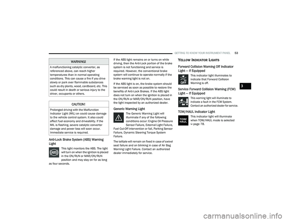
Anti-Lock Brake System (ABS) Warning
Light
This light monitors the ABS. The light
will turn on when the ignition is placed
in the ON/RUN or MAR/ON/RUN
position and may stay on for as long
as four seconds. If the ABS light remains on or turns on while
driving, then the Anti-Lock portion of the brake
system is not functioning and service is
required. However, the conventional brake
system will continue to operate normally if the
brake warning light is not on.
If the ABS light is on, the brake system should
be serviced as soon as possible to restore the
benefits of Anti-Lock Brakes. If the ABS light
does not turn on when the ignition is placed in
the ON/RUN or MAR/ON/RUN position, have
the light inspected by an authorized dealer.
Generic Warning Light
The Generic Warning Light will
illuminate if any of the following
conditions occur: Engine Oil Pressure
Sensor Failure, External Light Failure,
Fuel Cut-Off intervention or fail, Parking Sensor
Failure, Dynamic Steering Torque System
Failure.
The telltale will remain on fixed in case of swivel
seat failure and on blinking in case of Air Bag
Warning Light Failure. Contact an authorized
dealer immediately for service.
YELLOW INDICATOR LIGHTS
Forward Collision Warning Off Indicator
Light — If Equipped
This indicator light illuminates to
indicate that Forward Collision
Warning is off.
Service Forward Collision Warning (FCW)
Light — If Equipped
This warning light will illuminate to
indicate a fault in the FCW System.
Contact an authorized dealer for service.
TOW/HAUL Indicator Light
This indicator light will illuminate
when TOW/HAUL mode is selected
Ú page 78.
WARNING!
A malfunctioning catalytic converter, as
referenced above, can reach higher
temperatures than in normal operating
conditions. This can cause a fire if you drive
slowly or park over flammable substances
such as dry plants, wood, cardboard, etc. This
could result in death or serious injury to the
driver, occupants or others.
CAUTION!
Prolonged driving with the Malfunction
Indicator Light (MIL) on could cause damage
to the vehicle control system. It also could
affect fuel economy and driveability. If the
MIL is flashing, severe catalytic converter
damage and power loss will soon occur.
Immediate service is required.
3
21_VF_OM_EN_USC_t.book Page 53
Page 85 of 288

STARTING AND OPERATING83
An electronically actuated trailer brake
controller is required when towing a trailer
with electronically actuated brakes. When
towing a trailer equipped with a hydraulic
surge actuated brake system, an electronic
brake controller is not required.
Trailer brakes are recommended for trailers
over 1,000 lbs (453 kg) and may be required
for any trailer, for example trailers in excess
of 2,000 lbs (907 kg). Trailer brake require -
ments vary by local law, consult local legal
requirements where the trailer is to be towed
for trailer brake requirements.
Towing Requirements — Trailer Lights And
Wiring
Whenever you pull a trailer, regardless of the
trailer size, stoplights and turn signals on the
trailer are required for motoring safety.
The Trailer Tow Package may include a four- and
seven-pin wiring harness. Use a factory
approved trailer harness and connector.
NOTE:
Do not cut or splice wiring into the vehicle’s
wiring harness.
The electrical connections are all complete to
the vehicle but you must mate the harness to a
trailer connector. Refer to the following
illustrations. NOTE:
Disconnect trailer wiring connector from the
vehicle before launching a boat (or any other
device plugged into vehicle’s electrical
connect) into water.
Be sure to reconnect after clear from water
area.
Four-Pin Connector
WARNING!
Do not connect trailer brakes to your
vehicle's hydraulic brake lines. It can over -
load your brake system and cause it to fail.
You might not have brakes when you need
them and could have an accident.
Towing any trailer will increase your stop -
ping distance. When towing, you should
allow for additional space between your
vehicle and the vehicle in front of you.
Failure to do so could result in an accident.
CAUTION!
If the trailer weighs more than 1,000 lbs
(453 kg) loaded, it should have its own
brakes and they should be of adequate
capacity. Failure to do this could lead to
accelerated brake lining wear, higher brake
pedal effort, and longer stopping distances.
1 — Ground
2 — Tail Lamp
3 — Left Stop/Turn
4 — Right Stop/Turn
4
21_VF_OM_EN_USC_t.book Page 83