engine oil RAM PROMASTER 2022 Owners Manual
[x] Cancel search | Manufacturer: RAM, Model Year: 2022, Model line: PROMASTER, Model: RAM PROMASTER 2022Pages: 268, PDF Size: 13.26 MB
Page 5 of 268
3
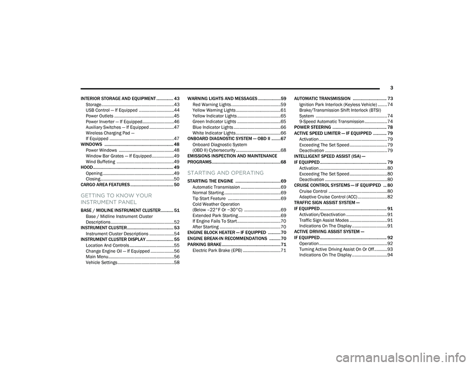
INTERIOR STORAGE AND EQUIPMENT ............... 43 Storage..............................................................43
USB Control — If Equipped ..............................44
Power Outlets ...................................................45
Power Inverter — If Equipped...........................46
Auxiliary Switches — If Equipped .....................47
Wireless Charging Pad —
If Equipped .......................................................47
WINDOWS ............................................................. 48
Power Windows ...............................................48
Window Bar Grates — If Equipped...................49
Wind Buffeting .................................................49
HOOD....................................................................... 49
Opening .............................................................49
Closing...............................................................50
CARGO AREA FEATURES ...................................... 50
GETTING TO KNOW YOUR
INSTRUMENT PANEL
BASE / MIDLINE INSTRUMENT CLUSTER........... 51
Base / Midline Instrument Cluster
Descriptions ......................................................52
INSTRUMENT CLUSTER......................................... 53
Instrument Cluster Descriptions .....................54
INSTRUMENT CLUSTER DISPLAY ........................ 55
Location And Controls ......................................55
Change Engine Oil — If Equipped ....................56
Main Menu........................................................56
Vehicle Settings ................................................58 WARNING LIGHTS AND MESSAGES ....................59
Red Warning Lights ..........................................59
Yellow Warning Lights ......................................61
Yellow Indicator Lights .....................................65
Green Indicator Lights .....................................65
Blue Indicator Lights ........................................66
White Indicator Lights ......................................66
ONBOARD DIAGNOSTIC SYSTEM — OBD II ........ 67
Onboard Diagnostic System
(OBD II) Cybersecurity ......................................68
EMISSIONS INSPECTION AND MAINTENANCE
PROGRAMS.............................................................68
STARTING AND OPERATING
STARTING THE ENGINE ........................................69
Automatic Transmission ..................................69
Normal Starting ................................................69
Tip Start Feature .............................................69
Cold Weather Operation
(Below –22°F Or −30°C) ...............................69
Extended Park Starting ....................................69
If Engine Fails To Start .....................................70
After Starting ....................................................70
ENGINE BLOCK HEATER — IF EQUIPPED ...........70
ENGINE BREAK-IN RECOMMENDATIONS ..........70
PARKING BRAKE ....................................................71
Electric Park Brake (EPB) ................................71 AUTOMATIC TRANSMISSION .............................. 73
Ignition Park Interlock (Keyless Vehicle) ........ 74
Brake/Transmission Shift Interlock (BTSI)
System ............................................................. 74
9-Speed Automatic Transmission ................... 74
POWER STEERING ................................................ 78
ACTIVE SPEED LIMITER — IF EQUIPPED ............ 79
Activation .......................................................... 79
Exceeding The Set Speed ................................ 79
Deactivation ..................................................... 79
INTELLIGENT SPEED ASSIST (ISA) —
IF EQUIPPED ........................................................... 79
Activation .......................................................... 80
Exceeding The Set Speed ................................ 80
Deactivation ..................................................... 80
CRUISE CONTROL SYSTEMS — IF EQUIPPED ... 80
Cruise Control .................................................. 80
Adaptive Cruise Control (ACC) ......................... 82
TRAFFIC SIGN ASSIST SYSTEM —
IF EQUIPPED ........................................................... 91
Activation/Deactivation ................................... 91
Traffic Sign Assist Modes ................................ 91
Indications On The Display .............................. 91
ACTIVE DRIVING ASSIST SYSTEM —
IF EQUIPPED ........................................................... 92
Operation .......................................................... 92
Turning Active Driving Assist On Or Off ........... 93
Indications On The Display .............................. 94
22_VF_OM_EN_USC_t.book Page 3
Page 7 of 268
5
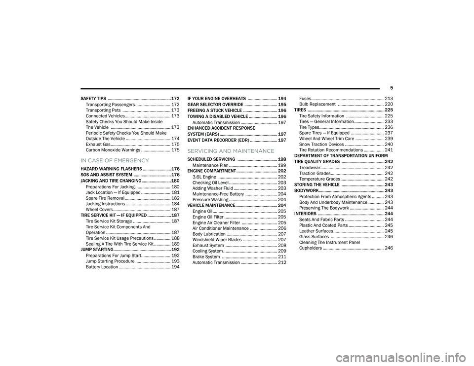
SAFETY TIPS ........................................................ 172 Transporting Passengers .............................. 172Transporting Pets ......................................... 173
Connected Vehicles....................................... 173
Safety Checks You Should Make Inside
The Vehicle ................................................... 173Periodic Safety Checks You Should Make
Outside The Vehicle ...................................... 174Exhaust Gas ................................................... 175Carbon Monoxide Warnings ......................... 175
IN CASE OF EMERGENCY
HAZARD WARNING FLASHERS ......................... 176
SOS AND ASSIST SYSTEM ................................. 176
JACKING AND TIRE CHANGING.......................... 180
Preparations For Jacking .............................. 180Jack Location — If Equipped ......................... 181Spare Tire Removal ....................................... 182
Jacking Instructions ...................................... 184Wheel Covers ................................................. 187
TIRE SERVICE KIT — IF EQUIPPED ..................... 187
Tire Service Kit Storage ................................ 187
Tire Service Kit Components And
Operation ....................................................... 187
Tire Service Kit Usage Precautions .............. 188
Sealing A Tire With Tire Service Kit .............. 189
JUMP STARTING................................................... 192
Preparations For Jump Start......................... 192Jump Starting Procedure .............................. 193Battery Location ............................................ 194 IF YOUR ENGINE OVERHEATS .......................... 194
GEAR SELECTOR OVERRIDE ............................. 195
FREEING A STUCK VEHICLE .............................. 196
TOWING A DISABLED VEHICLE ......................... 196 Automatic Transmission ............................... 197
ENHANCED ACCIDENT RESPONSE
SYSTEM (EARS) ................................................... 197
EVENT DATA RECORDER (EDR) ........................ 197
SERVICING AND MAINTENANCE
SCHEDULED SERVICING ................................... 198
Maintenance Plan ......................................... 199
ENGINE COMPARTMENT .................................... 202
3.6L Engine .................................................. 202
Checking Oil Level ......................................... 203
Adding Washer Fluid ..................................... 203
Maintenance-Free Battery ........................... 204Pressure Washing ......................................... 204
VEHICLE MAINTENANCE..................................... 204
Engine Oil ....................................................... 205
Engine Oil Filter ............................................. 205Engine Air Cleaner Filter .............................. 205Air Conditioner Maintenance ....................... 206
Body Lubrication ........................................... 207Windshield Wiper Blades ............................. 207
Exhaust System ............................................ 208
Cooling System .............................................. 209
Brake System ............................................... 211
Automatic Transmission ............................... 212 Fuses.............................................................. 213
Bulb Replacement ....................................... 220
TIRES .................................................................... 225
Tire Safety Information ................................ 225Tires — General Information ......................... 233
Tire Types....................................................... 236Spare Tires — If Equipped ............................ 237
Wheel And Wheel Trim Care ........................ 239Snow Traction Devices ................................. 240
Tire Rotation Recommendations ................. 241
DEPARTMENT OF TRANSPORTATION UNIFORM
TIRE QUALITY GRADES ...................................... 242
Treadwear...................................................... 242
Traction Grades ............................................. 242Temperature Grades..................................... 242
STORING THE VEHICLE ...................................... 243
BODYWORK .......................................................... 243
Protection From Atmospheric Agents .......... 243
Body And Underbody Maintenance ............. 243
Preserving The Bodywork ............................. 244
INTERIORS ........................................................... 244
Seats And Fabric Parts ................................. 244
Plastic And Coated Parts .............................. 245
Leather Surfaces........................................... 245
Glass Surfaces ............................................. 246Cleaning The Instrument Panel
Cupholders .................................................... 246
22_VF_OM_EN_USC_t.book Page 5
Page 11 of 268
9
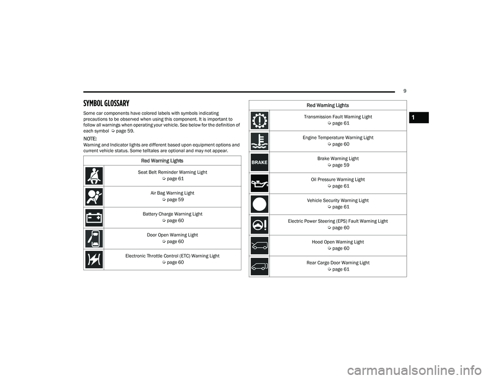
SYMBOL GLOSSARY
Some car components have colored labels with symbols indicating
precautions to be observed when using this component. It is important to
follow all warnings when operating your vehicle. See below for the definition of
each symbol Úpage 59.
NOTE:Warning and Indicator lights are different based upon equipment options and
current vehicle status. Some telltales are optional and may not appear.
Red Warning Lights
Seat Belt Reminder Warning Light
Úpage 61
Air Bag Warning Light Úpage 59
Battery Charge Warning Light Úpage 60
Door Open Warning Light Úpage 60
Electronic Throttle Control (ETC) Warning Light Úpage 60
Transmission Fault Warning Light
Úpage 61
Engine Temperature Warning Light Úpage 60
Brake Warning Light Úpage 59
Oil Pressure Warning Light Úpage 61
Vehicle Security Warning Light Úpage 61
Electric Power Steering (EPS) Fault Warning Light Úpage 60
Hood Open Warning Light Úpage 60
Rear Cargo Door Warning Light Úpage 61
Red Warning Lights
1
22_VF_OM_EN_USC_t.book Page 9
Page 54 of 268
52GETTING TO KNOW YOUR INSTRUMENT PANEL
BASE / MIDLINE INSTRUMENT CLUSTER
D
ESCRIPTIONS
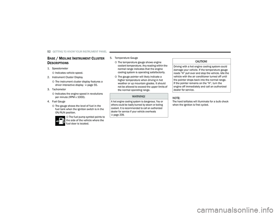
1. Speedometer
Indicates vehicle speed.
2. Instrument Cluster Display
The instrument cluster display features a
driver interactive display Ú page 55.
3. Tachometer
Indicates the engine speed in revolutions
per minute (RPM x 1000).
4. Fuel Gauge
The gauge shows the level of fuel in the
fuel tank when the ignition switch is in the
ON/RUN position.
The fuel pump symbol points to
the side of the vehicle where the
fuel door is located. 5. Temperature Gauge
The temperature gauge shows engine
coolant temperature. Any reading within the
normal range indicates that the engine
cooling system is operating satisfactorily.
The gauge pointer will likely indicate a
higher temperature when driving in hot
weather or up mountain grades. It should
not be allowed to exceed the upper limits of
the normal operating range.
NOTE:The hard telltales will illuminate for a bulb check
when the ignition is first cycled.
WARNING!
A hot engine cooling system is dangerous. You or
others could be badly burned by steam or boiling
coolant. It is recommended to call an authorized
dealer for service if your vehicle overheats
Ú
page 209.
CAUTION!
Driving with a hot engine cooling system could
damage your vehicle. If the temperature gauge
reads “H” pull over and stop the vehicle. Idle the
vehicle with the air conditioner turned off until
the pointer drops back into the normal range.
If the pointer remains on the “H”, turn the
engine off immediately and call an authorized
dealer for service.
22_VF_OM_EN_USC_t.book Page 52
Page 56 of 268
54GETTING TO KNOW YOUR INSTRUMENT PANEL
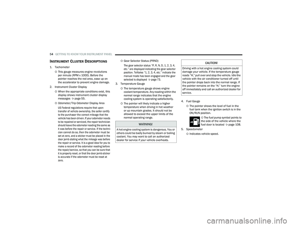
INSTRUMENT CLUSTER DESCRIPTIONS
1. Tachometer
This gauge measures engine revolutions
per minute (RPM x 1000). Before the
pointer reaches the red area, ease up on
the accelerator to prevent engine damage.
2. Instrument Cluster Display
When the appropriate conditions exist, this
display shows instrument cluster display
messages Ú page 55.
Odometer/Trip Odometer Display Area
US Federal regulations require that upon
transfer of vehicle ownership, the seller certify
to the purchaser the correct mileage that the
vehicle has been driven. If your odometer needs
to be repaired or serviced, the repair technician
should leave the odometer reading the same as
it was before the repair or service. If the techni -
cian cannot do so, then the odometer must be
set at zero, and a sticker must be placed in the
door jamb stating what the mileage was before
the repair or service. It is a good idea for you to
make a record of the odometer reading before
the repair/service, so that you can be sure that
it is properly reset, or that the door jamb sticker
is accurate if the odometer must be reset at
zero.
Gear Selector Status (PRND)
The gear selector status “P, R, N, D, 1, 2, 3, 4,
etc.” are displayed indicating the gear selector
position. Telltales “1, 2, 3, 4, etc.” indicate the
manual mode has been engaged and the gear
selected is displayed
Ú
page 73.
3. Temperature Gauge
The temperature gauge shows engine
coolant temperature. Any reading within the
normal range indicates that the engine
cooling system is operating satisfactorily.
The pointer will likely indicate a higher
temperature when driving in hot weather
or up mountain grades. It should not be
allowed to exceed the upper limits of the
normal operating range. 4. Fuel GaugeThe pointer shows the level of fuel in the
fuel tank when the ignition switch is in the
ON/RUN position.
The fuel pump symbol points to
the side of the vehicle where the
fuel door is located Ú page 108.
5. Speedometer
Indicates vehicle speed.
WARNING!
A hot engine cooling system is dangerous. You or
others could be badly burned by steam or boiling
coolant. You may want to call an authorized
dealer for service if your vehicle overheats.
CAUTION!
Driving with a hot engine cooling system could
damage your vehicle. If the temperature gauge
reads “H,” pull over and stop the vehicle. Idle the
vehicle with the air conditioner turned off until
the pointer drops back into the normal range. If
the pointer remains on the “H,” turn the engine
off immediately and call an authorized dealer for
service.
22_VF_OM_EN_USC_t.book Page 54
Page 58 of 268
56GETTING TO KNOW YOUR INSTRUMENT PANEL
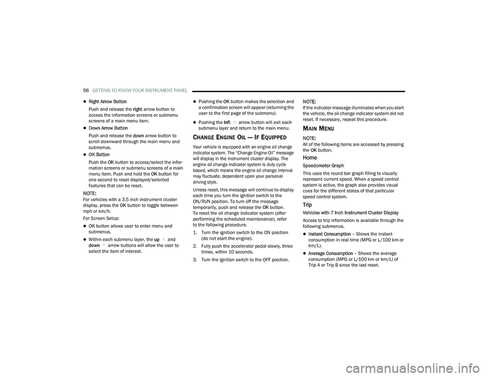
Right Arrow Button
Push and release the right arrow button to
access the information screens or submenu
screens of a main menu item.
Down Arrow Button
Push and release the down arrow button to
scroll downward through the main menu and
submenus.
OK Button
Push the OK button to access/select the infor -
mation screens or submenu screens of a main
menu item. Push and hold the OK button for
one second to reset displayed/selected
features that can be reset.
NOTE:For vehicles with a 3.5 inch instrument cluster
display, press the OK button to toggle between
mph or km/h.
For Screen Setup:
OK button allows user to enter menu and
submenus.
Within each submenu layer, the up and
down arrow buttons will allow the user to
select the item of interest.
Pushing the OK button makes the selection and
a confirmation screen will appear (returning the
user to the first page of the submenu).
Pushing the left arrow button will exit each
submenu layer and return to the main menu.
CHANGE ENGINE OIL — IF EQUIPPED
Your vehicle is equipped with an engine oil change
indicator system. The “Change Engine Oil” message
will display in the instrument cluster display. The
engine oil change indicator system is duty cycle
based, which means the engine oil change interval
may fluctuate, dependent upon your personal
driving style.
Unless reset, this message will continue to display
each time you turn the ignition switch to the
ON/RUN position. To turn off the message
temporarily, push and release the OK button.
To reset the oil change indicator system (after
performing the scheduled maintenance), refer
to the following procedure.
1. Turn the ignition switch to the ON position (do not start the engine).
2. Fully push the accelerator pedal slowly, three times, within 10 seconds.
3. Turn the ignition switch to the OFF position.
NOTE:If the indicator message illuminates when you start
the vehicle, the oil change indicator system did not
reset. If necessary, repeat this procedure.
MAIN MENU
NOTE:All of the following items are accessed by pressing
the OK button.
Home
Speedometer Graph
This uses the round bar graph filling to visually
represent current speed. When a speed control
system is active, the graph also provides visual
cues for the different states of that particular
speed control system.
Trip
Vehicles with 7 Inch Instrument Cluster Display
Access to trip information is available through the
following submenus.
Instant Consumption – Shows the instant
consumption in real time (MPG or L/100 km or
km/L).
Average Consumption – Shows the average
consumption (MPG or L/100 km or km/L) of
Trip A or Trip B since the last reset.
22_VF_OM_EN_USC_t.book Page 56
Page 63 of 268
GETTING TO KNOW YOUR INSTRUMENT PANEL61
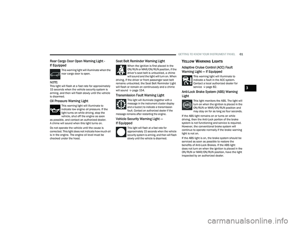
Rear Cargo Door Open Warning Light -
If Equipped
This warning light will illuminate when the
rear cargo door is open.
NOTE:This light will flash at a fast rate for approximately
15 seconds when the vehicle security system is
arming, and then will flash slowly until the vehicle
is disarmed.
Oil Pressure Warning Light
This warning light will illuminate to
indicate low engine oil pressure. If the
light turns on while driving, stop the
vehicle, shut off the engine as soon
as possible, and contact an authorized dealer.
A chime will sound when this light turns on.
Do not operate the vehicle until the cause is
corrected. This light does not indicate how much oil
is in the engine. The engine oil level must be
checked under the hood.
Seat Belt Reminder Warning Light
When the ignition is first placed in the
ON/RUN or MAR/ON/RUN position, if the
driver’s seat belt is unbuckled, a chime
will sound and the light will turn on. When
driving, if the driver or front passenger seat belt
remains unbuckled, the Seat Belt Reminder Light
will flash or remain on continuously and a chime
will sound Ú page 154.
Transmission Fault Warning Light
This light will illuminate (together with a
message in the instrument cluster display
and a buzzer) to indicate a transmission
fault. Contact an authorized dealer if the
message remains after restarting the engine.
Vehicle Security Warning Light —
If Equipped
This light will flash at a fast rate for
approximately 15 seconds when the vehicle
security system is arming, and then will flash
slowly until the vehicle is disarmed.
YELLOW WARNING LIGHTS
Adaptive Cruise Control (ACC) Fault
Warning Light — If Equipped
This warning light will illuminate to
indicate a fault in the ACC system.
Contact a local authorized dealer for
service Ú page 82.
Anti-Lock Brake System (ABS) Warning
Light
This light monitors the ABS. The light will
turn on when the ignition is placed in the
ON/RUN or MAR/ON/RUN position and
may stay on for as long as four seconds.
If the ABS light remains on or turns on while
driving, then the Anti-Lock portion of the brake
system is not functioning and service is required.
However, the conventional brake system will
continue to operate normally if the brake warning
light is not on.
If the ABS light is on, the brake system should be
serviced as soon as possible to restore the
benefits of Anti-Lock Brakes. If the ABS light
does not turn on when the ignition is placed in the
ON/RUN or MAR/ON/RUN position, have the light
inspected by an authorized dealer.
3
22_VF_OM_EN_USC_t.book Page 61
Page 64 of 268
62GETTING TO KNOW YOUR INSTRUMENT PANEL
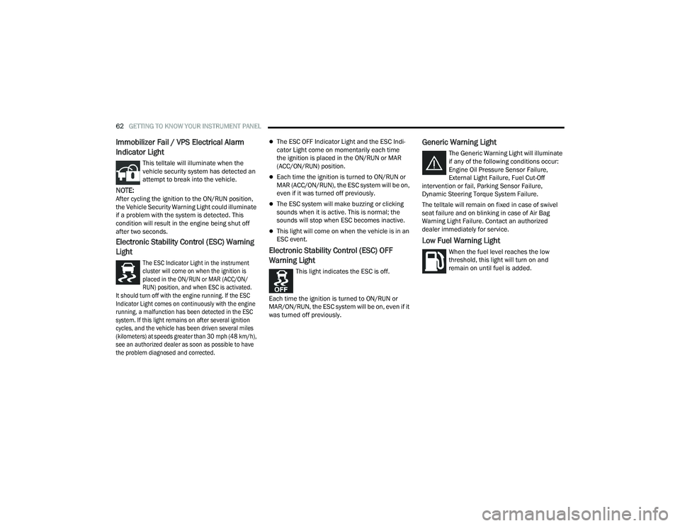
Immobilizer Fail / VPS Electrical Alarm
Indicator Light
This telltale will illuminate when the
vehicle security system has detected an
attempt to break into the vehicle.
NOTE:After cycling the ignition to the ON/RUN position,
the Vehicle Security Warning Light could illuminate
if a problem with the system is detected. This
condition will result in the engine being shut off
after two seconds.
Electronic Stability Control (ESC) Warning
Light
The ESC Indicator Light in the instrument
cluster will come on when the ignition is
placed in the ON/RUN or MAR (ACC/ON/
RUN) position, and when ESC is activated.
It should turn off with the engine running. If the ESC
Indicator Light comes on continuously with the engine
running, a malfunction has been detected in the ESC
system. If this light remains on after several ignition
cycles, and the vehicle has been driven several miles
(kilometers) at speeds greater than 30 mph (48 km/h),
see an authorized dealer as soon as possible to have
the problem diagnosed and corrected.
The ESC OFF Indicator Light and the ESC Indi -
cator Light come on momentarily each time
the ignition is placed in the ON/RUN or MAR
(ACC/ON/RUN) position.
Each time the ignition is turned to ON/RUN or
MAR (ACC/ON/RUN), the ESC system will be on,
even if it was turned off previously.
The ESC system will make buzzing or clicking
sounds when it is active. This is normal; the
sounds will stop when ESC becomes inactive.
This light will come on when the vehicle is in an
ESC event.
Electronic Stability Control (ESC) OFF
Warning Light
This light indicates the ESC is off.
Each time the ignition is turned to ON/RUN or
MAR/ON/RUN, the ESC system will be on, even if it
was turned off previously.
Generic Warning Light
The Generic Warning Light will illuminate
if any of the following conditions occur:
Engine Oil Pressure Sensor Failure,
External Light Failure, Fuel Cut-Off
intervention or fail, Parking Sensor Failure,
Dynamic Steering Torque System Failure.
The telltale will remain on fixed in case of swivel
seat failure and on blinking in case of Air Bag
Warning Light Failure. Contact an authorized
dealer immediately for service.
Low Fuel Warning Light
When the fuel level reaches the low
threshold, this light will turn on and
remain on until fuel is added.
22_VF_OM_EN_USC_t.book Page 62
Page 67 of 268

GETTING TO KNOW YOUR INSTRUMENT PANEL65
Transmission Temperature Warning Light
This warning light will illuminate to warn
of a high transmission fluid temperature.
This may occur with strenuous usage
such as trailer towing. If this light turns
on, stop the vehicle and run the engine at idle or
slightly faster, with the transmission in PARK (P) or
NEUTRAL (N), until the light turns off. Once the light
turns off, you may continue to drive normally.
YELLOW INDICATOR LIGHTS
Forward Collision Warning (FCW) OFF
Indicator Light — If Equipped
This indicator light will illuminate when
you switch FCW off or when driving
conditions obscure the sensor with snow,
heavy rain, or sun.
TOW/HAUL Indicator Light
This indicator light will illuminate when
TOW/HAUL mode is selected
Ú
page 110.
Keyless System Failure Light
The telltale will illuminate in the event of
keyless system failure.
Contact an authorized dealer as soon as possible.
Rain Sensor Failure Light
The telltale will illuminate in the case of
failure of the automatic windshield wiper.
Contact an authorized dealer as soon as
possible.
Exterior Lights Failure Light
The telltale will illuminate to indicate a
failure on the following lights: Daytime
Running Lights (DRLs) / parking lights /
trailer turn signal indicators (if present) /
trailer lights (if present) / side lights / turn signal
indicators / rear fog light / reversing light / brake
lights / license plate lights.
The failure may be caused by a blown bulb, a blown
protection fuse, or an interruption of the electrical
connection. Replace the bulb or the relevant fuse.
Contact an authorized dealer.
Fuel Cutoff Failure Light — If Equipped
This light will illuminate if there is a fuel
cutoff failure. If this light illuminates, take
it to an authorized dealer and have them
inspect it.
GREEN INDICATOR LIGHTS
Active Lane Management Indicator Light —
If Equipped
The Active Lane Management indicator light
illuminates solid green when both lane
markings have been detected and the
system is “armed” and ready to provide
visual and torque warnings if an unintentional lane
departure occurs
Ú
page 102.
WARNING!
If you continue operating the vehicle when the
Transmission Temperature Warning Light is
illuminated you could cause the fluid to boil over,
come in contact with hot engine or exhaust
components and cause a fire.
CAUTION!
Continuous driving with the Transmission
Temperature Warning Light illuminated will
eventually cause severe transmission damage
or transmission failure.
3
22_VF_OM_EN_USC_t.book Page 65
Page 72 of 268

70STARTING AND OPERATING
(Continued)
IF ENGINE FAILS TO START
If the engine fails to start after you have followed the
“Normal Starting” procedure, and the vehicle has not
experienced an extended park condition, it may be
flooded. Push the accelerator pedal all the way to the
floor and hold it there. Crank the engine for no more
than 10 seconds. This should clear any excess fuel in
case the engine is flooded. Leave the ignition in the
ON/RUN position, release the accelerator pedal and
repeat the “Normal Starting” procedure.
AFTER STARTING
The idle speed is controlled automatically, and it
will decrease as the engine warms up.
ENGINE BLOCK HEATER — IF EQUIPPED
The engine block heater warms the engine, and
permits quicker starts in cold weather. Connect the
cord to a standard 110-115 Volt AC electrical
outlet with a grounded, three-wire extension cord.
The engine block heater must be plugged in at
least one hour to have an adequate warming effect
on the engine.
ENGINE BREAK-IN RECOMMENDATIONS
A long break-in period is not required for the engine
and drivetrain (transmission and axle) in your
vehicle.
Drive moderately during the first 300 miles
(500 km). After the initial 60 miles (100 km),
speeds up to 50 or 55 mph (80 or 90 km/h) are
desirable.
While cruising, brief full-throttle acceleration within
the limits of local traffic laws contributes to a good
break-in. Wide-open throttle acceleration in low
gear can be detrimental and should be avoided.
The engine oil installed in the engine at the factory
is a high-quality energy conserving type lubricant.
Oil changes should be consistent with anticipated
climate conditions under which vehicle operations
will occur. For the recommended viscosity and
quality grades see Ú page 251.
CAUTION!
To prevent damage to the starter, do not crank
continuously for more than 10 seconds at a
time. Wait 10 to 15 seconds before trying again.
WARNING!
Never pour fuel or other flammable liquid into
the throttle body air inlet opening in an
attempt to start the vehicle. This could result
in flash fire causing serious personal injury.
Do not attempt to push or tow your vehicle to
get it started. Vehicles equipped with an auto -
matic transmission cannot be started this
way. Unburned fuel could enter the catalytic
converter and once the engine has started,
ignite and damage the converter and vehicle.
If the vehicle has a discharged battery,
booster cables may be used to obtain a start
from a booster battery or the battery in
another vehicle. This type of start can be
dangerous if done improperly Ú page 192.
CAUTION!
To prevent damage to the starter, do not
continuously crank the engine for more than
10 seconds at a time. Wait 10 to 15 seconds
before trying again.
WARNING!WARNING!
Remember to disconnect the engine block heater
cord before driving. Damage to the 110-115 Volt
electrical cord could cause electrocution.
CAUTION!
Never use Non-Detergent Oil or Straight Mineral
Oil in the engine or damage may result.
22_VF_OM_EN_USC_t.book Page 70