start stop button RAM PROMASTER 2022 Owners Manual
[x] Cancel search | Manufacturer: RAM, Model Year: 2022, Model line: PROMASTER, Model: RAM PROMASTER 2022Pages: 268, PDF Size: 13.26 MB
Page 18 of 268
16GETTING TO KNOW YOUR VEHICLE
SENTRY KEY
The Sentry Key Immobilizer System prevents
unauthorized vehicle operation by disabling the
engine. The system does not need to be armed or
activated. Operation is automatic, regardless of
whether the vehicle is locked or unlocked.
The system uses a key fob, keyless push button
ignition and a Radio Frequency (RF) receiver to
prevent unauthorized vehicle operation. Therefore,
only key fobs that are programmed to the vehicle
can be used to start and operate the vehicle.
The system will shut the engine off in two seconds
if an invalid key fob is used to start the engine.
If the Vehicle Security Light is on after the ignition
is placed in the ON/RUN position, it indicates that
there is a problem with the electronics.
All of the keys provided with your new vehicle have
been programmed to the vehicle electronics.
NOTE:A key fob that has not been programmed is also
considered an invalid key Úpage 256.
IGNITION SWITCH
KEYLESS ENTER ‘N GO™ IGNITION
This feature allows the driver to operate the
ignition switch with the push of a button as long as
the key fob is in the passenger compartment.
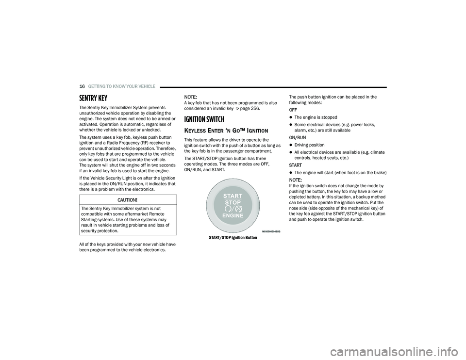
The START/STOP ignition button has three
operating modes. The three modes are OFF,
ON/RUN, and START.
START/STOP Ignition Button
The push button ignition can be placed in the
following modes:
OFF
The engine is stopped
Some electrical devices (e.g. power locks,
alarm, etc.) are still available
ON/RUN
Driving position
All electrical devices are available (e.g. climate
controls, heated seats, etc.)
START
The engine will start (when foot is on the brake)
NOTE:
If the ignition switch does not change the mode by
pushing the button, the key fob may have a low or
depleted battery. In this situation, a backup method
can be used to operate the ignition switch. Put the
nose side (side opposite of the mechanical key) of
the key fob against the START/STOP ignition button
and push to operate the ignition switch.
CAUTION!
The Sentry Key Immobilizer system is not
compatible with some aftermarket Remote
Starting systems. Use of these systems may
result in vehicle starting problems and loss of
security protection.
22_VF_OM_EN_USC_t.book Page 16
Page 20 of 268
18GETTING TO KNOW YOUR VEHICLE
HOW TO USE REMOTE START
Push and release the Remote Start button on the
key fob twice within five seconds. The vehicle
doors will lock, the parking lights will flash, and the
horn will chirp twice (if programmed). Then, the
engine will start, and the vehicle will remain in the
Remote Start mode for a 15 minute cycle.
Pushing the Remote Start button a third time shuts
the engine off.
NOTE:
With Remote Start, the engine will only run for
15 minutes.
Remote Start can only be used twice.
If an engine fault is present or fuel level is low,
the vehicle will start and then shut down in
10 seconds.
The park lights will turn on and remain on during
Remote Start mode.
For security, power window is disabled when the
vehicle is in the Remote Start mode.
The ignition must be placed in the ON/RUN posi -
tion before the Remote Start sequence can be
repeated for a third cycle.
All of the following conditions must be met before
the engine will Remote Start:
Gear selector in PARK
Doors closed
Hood closed
Rear cargo doors closed
Hazard switch off
Brake switch inactive (brake pedal not pressed)
Battery at an acceptable charge level
PANIC button not pushed
Fuel meets minimum requirement
System not disabled from previous Remote
Start event
Vehicle Security system not active
Malfunction Indicator Light (MIL) is not illuminated
Ignition in OFF position
TO EXIT REMOTE START MODE
To drive the vehicle after starting the Remote Start
system, push and release the START/STOP ignition
button while pressing the brake pedal prior to the
end of the 15 minute cycle.
The Remote Start system will turn the engine off if the
Remote Start button on the key fob is pushed again, or
if the engine is allowed to run for the entire 15 minute
cycle. Once the ignition is placed in the ON/RUN
position, the climate controls will resume the previously
set operations (temperature, blower control, etc.).
NOTE:To avoid unintentional shutdowns, the system will
disable for two seconds after receiving a valid
Remote Start request.
WARNING!
Do not start or run an engine in a closed garage
or confined area. Exhaust gas contains Carbon
Monoxide (CO) which is odorless and colorless.
Carbon Monoxide is poisonous and can cause
serious injury or death when inhaled.
Keep key fobs away from children. Operation
of the Remote Start system, windows, door
locks or other controls could cause serious
injury or death.
WARNING!
Do not start or run an engine in a closed garage or
confined area. Exhaust gas contains Carbon
Monoxide (CO) which is odorless and colorless.
Carbon Monoxide is poisonous and can cause
serious injury or death when inhaled.
Keep key fobs away from children. Operation
of the Remote Start system, windows, door
locks or other controls could cause serious
injury or death.
22_VF_OM_EN_USC_t.book Page 18
Page 21 of 268
GETTING TO KNOW YOUR VEHICLE19
For vehicles equipped with the Keyless Enter ‘n
Go™ — Passive Entry feature, the message
“Remote Start Active — Push Start Button” will
display in the instrument cluster display until you
push the START/STOP ignition button.
REMOTE START DEFROST MODE
A
CTIVATION — IF EQUIPPED
When Remote Start is active, and the outside
ambient temperature is 40°F (4.5°C) or below, the
system will automatically activate rear defrost for
15 minutes or less. The time is dependent on the
ambient temperature. Once the timer expires,
the system will automatically adjust the settings
depending on ambient conditions. See “Remote
Start Comfort Systems — If Equipped” in the next
section for detailed operation.
REMOTE START COMFORT SYSTEMS —
I
F EQUIPPED
When Remote Start is activated, the rear defrost
will automatically turn on in cold weather. The
vehicle will adjust the climate control settings
depending on the outside ambient temperature. Manual Temperature Control (MTC) — If Equipped
In ambient temperatures of 40°F (4.5°C) or
below, the climate settings will default to
maximum heat, with fresh air entering the
cabin. If the front defrost timer expires, the
vehicle will enter Mix Mode.
In ambient temperatures from 40°F (4.5°C) to
78°F (26°C), the climate settings will be based
on the last settings selected by the driver.
In ambient temperatures of 78°F (26°C) or
above, the climate settings will default to MAX
A/C, Bi-Level mode, with Recirculation on.
For more information on ATC, MTC, and climate
control settings, see Ú page 39.
NOTE:These features will stay on through the duration of
Remote Start, or until the ignition is placed in the
ON/RUN position. The climate control settings will
change, and exit the automatic defaults, if
manually adjusted by the driver while the vehicle is
in Remote Start mode. This includes turning the
climate controls off using the OFF button.
REMOTE START WINDSHIELD WIPER
D
E–ICER ACTIVATION — IF EQUIPPED
When Remote Start is active and the outside
ambient temperature is less than 33°F (0.6°C),
the Windshield Wiper De-Icer will activate. Exiting
Remote Start will resume its previous operation.
If the Windshield Wiper De-Icer was active, the
timer and operation will continue.
REMOTE START ABORT MESSAGE
The following messages will display in the
instrument cluster display if the vehicle fails to
remote start or exits Remote Start prematurely:
Remote Start Cancelled — Door Open
Remote Start Cancelled — Hood Open
Remote Start Cancelled — Fuel Low
Remote Start Cancelled — Rear Cargo Door Open
Remote Start Cancelled — Too Cold
Remote Start Cancelled — Time Expired
Remote Start Cancelled — System Fault
Remote Start Disabled — Start Vehicle to Reset
The message will stay active until the ignition is
placed in the ON/RUN position.
2
22_VF_OM_EN_USC_t.book Page 19
Page 30 of 268
28GETTING TO KNOW YOUR VEHICLE
Front Head Restraint Adjustment
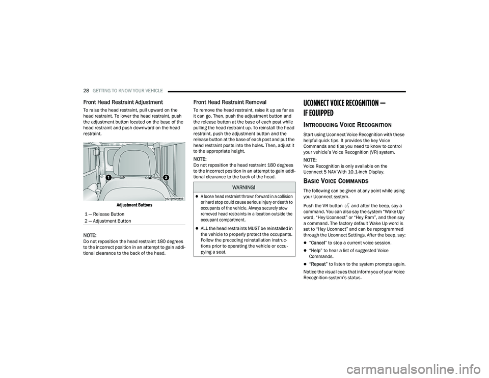
To raise the head restraint, pull upward on the
head restraint. To lower the head restraint, push
the adjustment button located on the base of the
head restraint and push downward on the head
restraint.
Adjustment Buttons
NOTE:Do not reposition the head restraint 180 degrees
to the incorrect position in an attempt to gain addi -
tional clearance to the back of the head.
Front Head Restraint Removal
To remove the head restraint, raise it up as far as
it can go. Then, push the adjustment button and
the release button at the base of each post while
pulling the head restraint up. To reinstall the head
restraint, push the adjustment button and the
release button at the base of each post and put the
head restraint posts into the holes. Then, adjust it
to the appropriate height.
NOTE:Do not reposition the head restraint 180 degrees
to the incorrect position in an attempt to gain addi -
tional clearance to the back of the head.
UCONNECT VOICE RECOGNITION —
IF EQUIPPED
INTRODUCING VOICE RECOGNITION
Start using Uconnect Voice Recognition with these
helpful quick tips. It provides the key Voice
Commands and tips you need to know to control
your vehicle’s Voice Recognition (VR) system.
NOTE:Voice Recognition is only available on the
Uconnect 5 NAV With 10.1-inch Display.
BASIC VOICE COMMANDS
The following can be given at any point while using
your Uconnect system.
Push the VR button and after the beep, say a
command. You can also say the system “Wake Up”
word, “Hey Uconnect” or “Hey Ram”, and then say
a command. The factory default Wake Up word is
set to “Hey Uconnect” and can be reprogrammed
through the Uconnect Settings. After the beep, say:
“ Cancel ” to stop a current voice session.
“Help ” to hear a list of suggested Voice
Commands.
“ Repeat ” to listen to the system prompts again.
Notice the visual cues that inform you of your Voice
Recognition system’s status.
1 — Release Button
2 — Adjustment Button
WARNING!
A loose head restraint thrown forward in a collision
or hard stop could cause serious injury or death to
occupants of the vehicle. Always securely stow
removed head restraints in a location outside the
occupant compartment.
ALL the head restraints MUST be reinstalled in
the vehicle to properly protect the occupants.
Follow the preceding reinstallation instruc
-
tions prior to operating the vehicle or occu -
pying a seat.
22_VF_OM_EN_USC_t.book Page 28
Page 71 of 268

69
STARTING AND OPERATING
STARTING THE ENGINE
Before starting your vehicle, adjust your seat,
adjust both inside and outside mirrors, and fasten
your seat belts.
AUTOMATIC TRANSMISSION
The gear selector must be in the PARK or NEUTRAL
position before you can start the engine. Press the
brake pedal before shifting to any driving gear.
NOTE:You must press the brake pedal before shifting out
of PARK.
NORMAL STARTING
NOTE:Normal starting of either a cold or warm engine is
obtained without pumping or pressing the accel-
erator pedal.
Proceed as follows:
1. Set the Electric Park Brake (EPB) and put the gear selector in the PARK or NEUTRAL position.
2. Press on the brake pedal, without pressing the accelerator.
3. Press the START/STOP ignition button and release it as soon as the engine is started.
4. If the engine does not start, place the ignition in the OFF position and wait 10-15 seconds
before attempting to restart the engine.
TIP START FEATURE
Do not press the accelerator. Press briefly the
START/STOP ignition button and release it. The starter
motor will continue to run but will automatically
disengage when the engine is running.
COLD WEATHER OPERATION
(B
ELOW –22°F OR −30°C)
To ensure reliable starting at these temperatures,
use of an externally powered electric engine block
heater (available from an authorized dealer) is
recommended.
EXTENDED PARK STARTING
NOTE:Extended Park condition occurs when the vehicle
has not been started or driven for at least 30 days.
1. Install a battery charger or jumper cables to
the battery to ensure a full battery charge
during the crank cycle.
2. Place the ignition in the START position and release it when the engine starts.
3. If the engine fails to start within 10 seconds, place the ignition in the OFF position, wait
10 to 15 seconds to allow the starter to cool,
then repeat the “Extended Park Starting”
procedure.
4. If the engine fails to start after eight attempts, allow the starter to cool for at least
10 minutes, then repeat the procedure.
WARNING!
Never leave children alone in a vehicle, or with
access to an unlocked vehicle.
Allowing children to be in a vehicle unattended
is dangerous for a number of reasons. A child
or others could be seriously or fatally injured.
Children should be warned not to touch the
parking brake, brake pedal or the transmis -
sion gear selector.
Do not leave the key fob in or near the vehicle
(or in a location accessible to children). A child
could operate power windows, other controls,
or move the vehicle.
4
22_VF_OM_EN_USC_t.book Page 69
Page 84 of 268

82STARTING AND OPERATING
(Continued)
To Accelerate For Passing
While the Cruise Control system is set, press the
accelerator to pass as you would normally. When
the pedal is released, the vehicle will return to the
set speed.
USING CRUISE CONTROL ON HILLS
The transmission may downshift on hills to
maintain the vehicle set speed.
The Cruise Control system maintains speed up and
down hills. A slight speed change on moderate hills
is normal. On steep hills, a greater speed loss or
gain may occur so it may be preferable to drive
without Cruise Control.
To Resume Speed
To resume a previously set speed, push the RES
button and release. Resume can be used at any
speed above 20 mph (32 km/h) up to the
maximum speed of 100 mph (160 km/h).
To Deactivate
A soft tap on the brake pedal, pushing the CANC
button, or normal brake pressure while slowing the
vehicle will deactivate the Cruise Control without
erasing the set speed from memory.
Pushing the on/off button or placing the ignition
in the OFF position erases the set speed from
memory.
ADAPTIVE CRUISE CONTROL (ACC)
Adaptive Cruise Control (ACC) increases the driving
convenience provided by Cruise Control while
traveling on highways and major roadways.
However, it is not a safety system and not designed
to prevent collisions. The Cruise Control function
performs differently if your vehicle is not equipped
with ACC Ú page 80.
ACC will allow you to keep Cruise Control engaged
in light to moderate traffic conditions without the
constant need to reset your speed. ACC utilizes a
radar sensor and a forward facing camera
designed to detect a vehicle directly ahead of you
to maintain a set speed.
NOTE:
If the ACC sensor detects a vehicle ahead, ACC
will apply limited braking or accelerate (not to
exceed the original set speed) automatically to
maintain a preset following distance, while
matching the speed of the vehicle ahead.
Any chassis/suspension or tire size modifica -
tions to the vehicle will affect the performance
of the Adaptive Cruise Control and Forward Colli -
sion Warning system.
Fixed Speed Cruise Control (ACC not enabled)
will not detect vehicles directly ahead of you.
Always be aware of the feature selected
Ú page 256.
WARNING!
Cruise Control can be dangerous where the
system cannot maintain a constant speed.
Your vehicle could go too fast for the conditions,
and you could lose control and have an accident.
Do not use Cruise Control in heavy traffic or on
roads that are winding, icy, snow-covered or
slippery.
WARNING!
Adaptive Cruise Control (ACC) is a conve -
nience system. It is not a substitute for active
driver involvement. It is always the driver’s
responsibility to be attentive of road, traffic,
and weather conditions, vehicle speed,
distance to the vehicle ahead and, most
importantly, brake operation to ensure safe
operation of the vehicle under all road condi -
tions. Your complete attention is always
required while driving to maintain safe control
of your vehicle. Failure to follow these warn -
ings can result in a collision and death or
serious personal injury.
The ACC system:
Does not react to pedestrians, oncoming
vehicles, and stationary objects (e.g., a
stopped vehicle in a traffic jam or a
disabled vehicle).
22_VF_OM_EN_USC_t.book Page 82
Page 88 of 268
86STARTING AND OPERATING
NOTE:
If your vehicle is at standstill longer than two
seconds, the driver will either have to push the
RES (resume) button, or apply the accelerator
pedal to reengage the Adaptive Cruise Control
(ACC) to the existing set speed.
ACC cannot be resumed if there is a stationary
vehicle in front of your vehicle in close proximity.
To Vary The Speed Setting
To Increase Or Decrease The Set Speed
After setting a speed, you can increase the set
speed by pushing the SET (+) button, or decrease
speed by pushing the SET (-) button. U.S. Speed (mph)
Pushing the SET (+)
, or SET (-) button once will
result in a 1 mph speed adjustment. Each
subsequent tap of the button results in an
adjustment of 1 mph.
If the button is continually pushed, the set speed
will continue to adjust in 5 mph increments until
the button is released. The new set speed is
reflected in the instrument cluster display.
Metric Speed (km/h)
Pushing the SET (+) , or SET (-) button once will
result in a 1 km/h speed adjustment. Each
subsequent tap of the button results in an
adjustment of 1 km/h.
If the button is continually pushed, the set speed
will continue to adjust in 10 km/h increments
until the button is released. The new set speed is
reflected in the instrument cluster display.
NOTE:When you override and push the SET (+) button or
SET (-) button, the new set speed will be the current
speed of the vehicle.
When ACC Is Active
When you use the SET (-) button to decelerate, if
the engine’s braking power does not slow the
vehicle sufficiently to reach the set speed, the
brake system will automatically slow the vehicle.
The ACC system decelerates the vehicle to a full
stop when following the vehicle in front. If your
vehicle follows the vehicle in front to a standstill,
after two seconds the driver will either have to
push the RES (resume) button, or apply the
accelerator pedal to reengage the ACC to the
existing set speed.
The ACC system maintains set speed when
driving uphill and downhill. However, a slight
speed change on moderate hills is normal.
In addition, downshifting may occur while
climbing uphill or descending downhill. This is
normal operation and necessary to maintain set
speed. When driving uphill and downhill, the
ACC system will cancel if the braking tempera -
ture exceeds normal range (overheated).
Setting The Following Distance In ACC
The specified following distance for ACC can be set
by varying the distance setting between four bars
(longest), three bars (long), two bars (medium) and
one bar (short). Using this distance setting and
the vehicle speed, ACC calculates and sets the
distance to the vehicle ahead. This distance
setting will show in the instrument cluster display.
WARNING!
The Resume function should only be used if traffic
and road conditions permit. Resuming a set speed
that is too high or too low for prevailing traffic and
road conditions could cause the vehicle to
accelerate or decelerate too sharply for safe
operation. Failure to follow these warnings can result
in a collision and death or serious personal injury.
22_VF_OM_EN_USC_t.book Page 86
Page 89 of 268

STARTING AND OPERATING87
Distance Settings
To adjust the distance setting, push the Distance
Setting Button and release. Each time the button is
pushed, the distance setting decreases by one bar
(longer). Once the longest setting is reached, if the
button is pushed again it will be set to the shortest
setting available.
If a slower moving vehicle is detected in the same
lane, the instrument cluster display will show the
ACC Set With Target Detected Light. The system
will then adjust vehicle speed automatically to
maintain the distance setting, regardless of the
set speed.
The vehicle will then maintain the set distance until:
The vehicle ahead accelerates to a speed above
the set speed.
The vehicle ahead moves out of your lane or
view of the sensor.
The distance setting is changed.
The system disengages Ú
page 84.
The maximum braking applied by ACC is limited;
however, the driver can always apply the brakes
manually, if necessary.
NOTE:The brake lights will illuminate whenever the ACC
system applies the brakes.
A Proximity Warning will alert the driver if ACC
predicts that its maximum braking level is not
sufficient to maintain the set distance. If this
occurs, a visual alert “BRAKE!” will flash in the
instrument cluster display and a chime will sound
while ACC continues to apply its maximum braking
force.
NOTE:The “BRAKE!” screen in the instrument cluster
display is a warning for the driver to take action
and does not necessarily mean that the Forward
Collision Warning system is applying the brakes
autonomously.
Overtake Aid
When driving with Adaptive Cruise Control (ACC)
engaged and following a vehicle, the system will
provide an additional acceleration up to the ACC
set speed to assist in passing the vehicle. This
additional acceleration is triggered when the driver
utilizes the left turn signal and will only be active
when passing on the left hand side.
ACC Operation At Stop
In the event that the ACC system brings your
vehicle to a standstill while following a vehicle in
front, if the vehicle in front starts moving within two
seconds of your vehicle coming to a standstill, your
vehicle will resume motion without the need for
any driver action.
If the vehicle in front does not start moving within
two seconds of your vehicle coming to a standstill,
the driver will either have to push the RES (resume)
button, or apply the accelerator pedal to reengage
the ACC to the existing set speed.
NOTE:After the ACC system holds your vehicle at a stand -
still for approximately three consecutive minutes,
the parking brake will be activated, and the ACC
system will be cancelled.
While ACC is holding your vehicle at a standstill, if
the driver seat belt is unbuckled or the driver door
is opened, the parking brake will be activated, and
the ACC system will be cancelled.
1 — Longest Distance Setting (Four Bars)
2 — Medium Distance Setting (Two Bars)
3 — Long Distance Setting (Three Bars)
4 — Short Distance Setting (One Bar)
4
22_VF_OM_EN_USC_t.book Page 87
Page 108 of 268
106STARTING AND OPERATING
NOTE:
If snow, ice, mud, or any foreign substance builds up
on the camera lens, clean the lens, rinse with water,
and dry with a soft cloth. Do not cover the lens.
SURROUND VIEW CAMERA SYSTEM —
IF EQUIPPED
Your vehicle may be equipped with the Surround View
Camera system that allows you to see an on-screen
image of the surroundings and Top View of your vehicle
whenever the gear selector is put into REVERSE or a
different view is selected through the touchscreen soft
buttons. The Top View of the vehicle will show which
doors are open. The image will be displayed on the
touchscreen display along with a caution note “Check
Entire Surroundings” across the top of the screen. After five seconds, this note will disappear. The
Surround View Camera system is comprised of four
sequential cameras located in the front grille, rear
CHMSL (top rear of the vehicle below the center light)
and side mirrors.
NOTE:The Surround View Camera system has program
-
mable settings that may be selected through the
Uconnect system Ú page 120.
When the vehicle is shifted into REVERSE, the Rear
View and Top View is the default view of the system.
When the vehicle is shifted out of REVERSE (with
camera delay turned on), the camera image will
continue to be displayed for up to 10 seconds unless
the vehicle speed exceeds 8 mph (13 km/h), the
vehicle is shifted into PARK, or the ignition is placed in
the OFF position. There is a touchscreen button “X” to
disable the display of the camera image.
When the vehicle is shifted out of REVERSE (with
camera delay turned off), the Surround View system is
exited and the last known screen appears again.
Whenever the Rear View Camera image is activated
through the Back Up Camera button in the Controls
menu, and the vehicle speed is greater than, or equal
to, 8 mph (13 km/h), a display timer for the image is
initiated. The image will continue to be displayed until
the display timer exceeds 10 seconds.
NOTE:
If the vehicle speed remains below 8 mph
(13 km/h), the Rear View Camera image will be
displayed continuously until deactivated via the
touchscreen button "X", the transmission is
shifted into PARK, or the ignition is placed in the
OFF position.
The touchscreen button "X" to disable display of
the camera image is made available ONLY when
the vehicle is not in REVERSE.
When enabled, active guidelines are overlaid on
the image to illustrate the width of the vehicle,
including the side view mirrors and its projected
back up path based on the steering wheel position.
Different colored zones indicate the distance to
the rear of the vehicle.
The following table shows the approximate
distances for each zone:
CAUTION!
To avoid vehicle damage, ParkView should
only be used as a parking aid. The ParkView
camera is unable to view every obstacle or
object in your drive path.
To avoid vehicle damage, the vehicle must be
driven slowly when using ParkView to be able
to stop in time when an obstacle is seen. It is
recommended that the driver look frequently
over his/her shoulder when using ParkView.
Zone Distance To The Rear Of The Vehicle
Red 0 - 1 ft (0 - 30 cm)
Yellow 1 ft - 6.5 ft (30 cm - 2 m) Green 6.5 ft or greater (2 m or greater)
22_VF_OM_EN_USC_t.book Page 106
Page 168 of 268

166SAFETY
If you do have a collision which deploys the air
bags, any or all of the following may occur:
The air bag material may sometimes cause abra -
sions and/or skin reddening to the occupants as
the air bags deploy and unfold. The abrasions are
similar to friction rope burns or those you might
get sliding along a carpet or gymnasium floor.
They are not caused by contact with chemicals.
They are not permanent and normally heal
quickly. However, if you haven’t healed signifi -
cantly within a few days, or if you have any blis -
tering, see your doctor immediately.
As the air bags deflate, you may see some
smoke-like particles. The particles are a normal
by-product of the process that generates the
non-toxic gas used for air bag inflation. These
airborne particles may irritate the skin, eyes,
nose, or throat. If you have skin or eye irritation,
rinse the area with cool water. For nose or throat
irritation, move to fresh air. If the irritation
continues, see your doctor. If these particles
settle on your clothing, follow the garment
manufacturer’s instructions for cleaning.
Do not drive your vehicle after the air bags have
deployed. If you are involved in another collision,
the air bags will not be in place to protect you.
NOTE:
Air bag covers may not be obvious in the interior
trim, but they will open during air bag deployment.
After any collision, the vehicle should be taken
to an authorized dealer immediately.
Fuel Cut Off Switch
Your vehicle is equipped with a Fuel Cut Off switch.
In the event of an accident, if the communication
network remains intact, and the power remains
intact, depending on the nature of the event, the
Fuel Cut Off Switch may perform the following
functions:
Cut off fuel to the engine and turn off the
engine.
Flash hazard lights as long as the battery has
power or until the hazard light button is pressed.
The hazard lights can be deactivated by
pressing the hazard light button.
Turn on the interior lights, which remain on as
long as the battery has power.
Unlock the power door locks.
NOTE:
After an accident, remember to cycle the ignition to
the STOP (OFF/LOCK) position and remove the key
from the ignition switch to avoid draining the battery.
Carefully check the vehicle for fuel leaks in the
engine compartment and on the ground near the
engine compartment and fuel tank before resetting
the system and starting the engine. If there are no
fuel leaks or damage to the vehicle electrical devices
(e.g. headlights) after an accident, reset the Fuel Cut
Off Switch by following the procedure described
below. If you have any doubt, contact an authorized
dealer.
WARNING!
Deployed air bags and seat belt pretensioners
cannot protect you in another collision. Have the air
bags, seat belt pretensioners, and the seat belt
retractor assemblies replaced by an authorized
dealer immediately. Also, have the Occupant
Restraint Controller System serviced as well.
22_VF_OM_EN_USC_t.book Page 166