tow RAM PROMASTER 2022 Owners Manual
[x] Cancel search | Manufacturer: RAM, Model Year: 2022, Model line: PROMASTER, Model: RAM PROMASTER 2022Pages: 268, PDF Size: 13.26 MB
Page 6 of 268
4
Minimum Risk Maneuver.................................95
System Status...................................................95
System Operation/Limitations ........................96
PARKSENSE FRONT/REAR PARK ASSIST —
IF EQUIPPED .......................................................... 96
ParkSense Sensors ..........................................97
ParkSense Warning Display.............................97
ParkSense Display ...........................................97
Enabling And Disabling ParkSense .............. 100
Service The ParkSense Park Assist
System ........................................................... 100 ParkSense Park Assist Failure Indications .. 101
Cleaning The ParkSense System ................. 101ParkSense Park Assist System Usage
Precautions .................................................... 101
LANESENSE — IF EQUIPPED ............................. 102
LaneSense Operation ................................... 102Turning LaneSense On Or Off ....................... 103
LaneSense Warning Message ...................... 103Changing LaneSense Status ........................ 105
PARKVIEW REAR BACK UP CAMERA .............. 105
SURROUND VIEW CAMERA SYSTEM —
IF EQUIPPED ......................................................... 106
REFUELING THE VEHICLE ................................... 108
Loose Fuel Filler Cap Message..................... 109 VEHICLE LOADING .............................................. 109
Vehicle Certification Label ............................ 109
Gross Vehicle Weight Rating (GVWR) .......... 109
Gross Axle Weight Rating (GAWR) ............... 109
Tire Size ......................................................... 109
Rim Size ......................................................... 110
Inflation Pressure .......................................... 110
Curb Weight ................................................... 110
Overloading.................................................... 110
Loading ......................................................... 110
TRAILER TOWING ................................................ 110
Common Towing Definitions......................... 110
Trailer Hitch Classification ............................ 112
Trailer Towing Weights (Maximum Trailer
Weight Ratings) ............................................ 113
Trailer And Tongue Weight ........................... 113Towing Requirements .................................. 113
Towing Tips ................................................... 115
RECREATIONAL TOWING (BEHIND
MOTORHOME) .................................................... 116
Towing This Vehicle Behind Another
Vehicle ........................................................... 116
Recreational Towing...................................... 117
DRIVING TIPS ....................................................... 117
Driving On Slippery Surfaces ....................... 117
Driving Through Water ................................. 118
MULTIMEDIA
UCONNECT SYSTEMS ......................................... 119
CYBERSECURITY ................................................. 119
UCONNECT SETTINGS ........................................ 120 Customer Programmable Features ............. 120
RADIO OPERATION AND MOBILE PHONES...... 136
Regulatory And Safety Information .............. 136
SAFETY
SAFETY FEATURES .............................................. 137Anti-Lock Brake System (ABS)...................... 137
Electronic Brake Control (EBC) System ...... 138
AUXILIARY DRIVING SYSTEMS .......................... 142
Blind Spot Monitoring (BSM) —
If Equipped ................................................... 142
Forward Collision Warning (FCW) With
Mitigation — If Equipped ............................... 148
Tire Pressure Monitoring System (TPMS) ... 151
OCCUPANT RESTRAINT SYSTEMS ................... 154
Occupant Restraint Systems Features ....... 154
Important Safety Precautions ...................... 154
Seat Belt Systems ........................................ 154
Supplemental Restraint Systems (SRS) ...... 161Child Restraints ............................................. 168
22_VF_OM_EN_USC_t.book Page 4
Page 7 of 268
5
SAFETY TIPS ........................................................ 172 Transporting Passengers .............................. 172Transporting Pets ......................................... 173
Connected Vehicles....................................... 173
Safety Checks You Should Make Inside
The Vehicle ................................................... 173Periodic Safety Checks You Should Make
Outside The Vehicle ...................................... 174Exhaust Gas ................................................... 175Carbon Monoxide Warnings ......................... 175
IN CASE OF EMERGENCY
HAZARD WARNING FLASHERS ......................... 176
SOS AND ASSIST SYSTEM ................................. 176
JACKING AND TIRE CHANGING.......................... 180
Preparations For Jacking .............................. 180Jack Location — If Equipped ......................... 181Spare Tire Removal ....................................... 182
Jacking Instructions ...................................... 184Wheel Covers ................................................. 187
TIRE SERVICE KIT — IF EQUIPPED ..................... 187
Tire Service Kit Storage ................................ 187
Tire Service Kit Components And
Operation ....................................................... 187
Tire Service Kit Usage Precautions .............. 188
Sealing A Tire With Tire Service Kit .............. 189
JUMP STARTING................................................... 192
Preparations For Jump Start......................... 192Jump Starting Procedure .............................. 193Battery Location ............................................ 194 IF YOUR ENGINE OVERHEATS .......................... 194
GEAR SELECTOR OVERRIDE ............................. 195
FREEING A STUCK VEHICLE .............................. 196
TOWING A DISABLED VEHICLE ......................... 196 Automatic Transmission ............................... 197
ENHANCED ACCIDENT RESPONSE
SYSTEM (EARS) ................................................... 197
EVENT DATA RECORDER (EDR) ........................ 197
SERVICING AND MAINTENANCE
SCHEDULED SERVICING ................................... 198
Maintenance Plan ......................................... 199
ENGINE COMPARTMENT .................................... 202
3.6L Engine .................................................. 202
Checking Oil Level ......................................... 203
Adding Washer Fluid ..................................... 203
Maintenance-Free Battery ........................... 204Pressure Washing ......................................... 204
VEHICLE MAINTENANCE..................................... 204
Engine Oil ....................................................... 205
Engine Oil Filter ............................................. 205Engine Air Cleaner Filter .............................. 205Air Conditioner Maintenance ....................... 206
Body Lubrication ........................................... 207Windshield Wiper Blades ............................. 207
Exhaust System ............................................ 208
Cooling System .............................................. 209
Brake System ............................................... 211
Automatic Transmission ............................... 212 Fuses.............................................................. 213
Bulb Replacement ....................................... 220
TIRES .................................................................... 225
Tire Safety Information ................................ 225Tires — General Information ......................... 233
Tire Types....................................................... 236Spare Tires — If Equipped ............................ 237
Wheel And Wheel Trim Care ........................ 239Snow Traction Devices ................................. 240
Tire Rotation Recommendations ................. 241
DEPARTMENT OF TRANSPORTATION UNIFORM
TIRE QUALITY GRADES ...................................... 242
Treadwear...................................................... 242
Traction Grades ............................................. 242Temperature Grades..................................... 242
STORING THE VEHICLE ...................................... 243
BODYWORK .......................................................... 243
Protection From Atmospheric Agents .......... 243
Body And Underbody Maintenance ............. 243
Preserving The Bodywork ............................. 244
INTERIORS ........................................................... 244
Seats And Fabric Parts ................................. 244
Plastic And Coated Parts .............................. 245
Leather Surfaces........................................... 245
Glass Surfaces ............................................. 246Cleaning The Instrument Panel
Cupholders .................................................... 246
22_VF_OM_EN_USC_t.book Page 5
Page 12 of 268
10
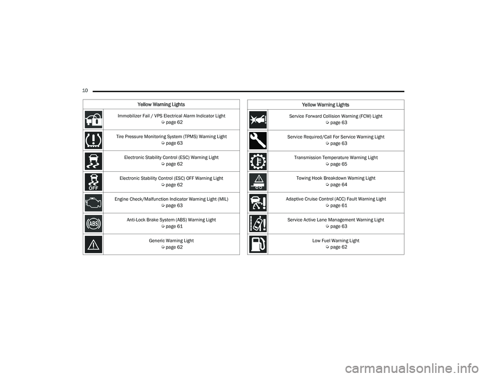
Yellow Warning Lights
Immobilizer Fail / VPS Electrical Alarm Indicator Light Úpage 62
Tire Pressure Monitoring System (TPMS) Warning Light Úpage 63
Electronic Stability Control (ESC) Warning Light Úpage 62
Electronic Stability Control (ESC) OFF Warning Light Úpage 62
Engine Check/Malfunction Indicator Warning Light (MIL) Úpage 63
Anti-Lock Brake System (ABS) Warning Light Úpage 61
Generic Warning Light Úpage 62Service Forward Collision Warning (FCW) Light
Úpage 63
Service Required/Call For Service Warning Light Úpage 63
Transmission Temperature Warning Light Úpage 65
Towing Hook Breakdown Warning Light Úpage 64
Adaptive Cruise Control (ACC) Fault Warning Light Úpage 61
Service Active Lane Management Warning Light Úpage 63
Low Fuel Warning Light Úpage 62
Yellow Warning Lights
22_VF_OM_EN_USC_t.book Page 10
Page 13 of 268
11
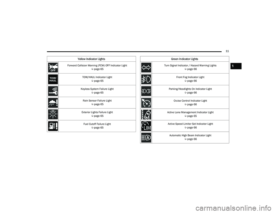
Yellow Indicator Lights
Forward Collision Warning (FCW) OFF Indicator Light Úpage 65
TOW/HAUL Indicator Light Úpage 65
Keyless System Failure Light Úpage 65
Rain Sensor Failure Light Úpage 65
Exterior Lights Failure Light Úpage 65
Fuel Cutoff Failure Light Úpage 65
Green Indicator Lights
Turn Signal Indicator / Hazard Warning Lights
Úpage 66
Front Fog Indicator Light Úpage 66
Parking/Headlights On Indicator Light Úpage 66
Cruise Control Indicator Light Úpage 66
Active Lane Management Indicator Light Úpage 65
Active Speed Limiter Set Indicator Light Úpage 66
Automatic High Beam Indicator Light Úpage 661
22_VF_OM_EN_USC_t.book Page 11
Page 27 of 268
GETTING TO KNOW YOUR VEHICLE25
Lumbar Support — If Equipped
This feature allows you to increase or decrease the
amount of lumbar support. The lumbar control
knob is located on the rear upper outboard side of
the driver's seatback. Rotate the control forward to
increase and rearward to decrease the desired
amount of lumbar support.
Suspension Seat — If Equipped
The seat is equipped with a mechanical spring
system and hydraulic shock absorber to ensure
maximum comfort and safety. The system of
springs also effectively absorbs impact from
uneven road surfaces. Damper Weight Adjustment
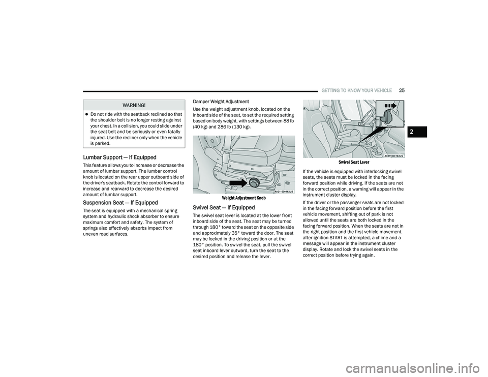
Use the weight adjustment knob, located on the
inboard side of the seat, to set the required setting
based on body weight, with settings between 88 lb
(40 kg) and 286 lb (130 kg).
Weight Adjustment Knob
Swivel Seat — If Equipped
The swivel seat lever is located at the lower front
inboard side of the seat. The seat may be turned
through 180° toward the seat on the opposite side
and approximately 35° toward the door. The seat
may be locked in the driving position or at the
180° position. To swivel the seat, pull the swivel
seat inboard lever outward, turn the seat to the
desired position and release the lever.
Swivel Seat Lever
If the vehicle is equipped with interlocking swivel
seats, the seats must be locked in the facing
forward position while driving. If the seats are not
in the correct position, a warning will appear in the
instrument cluster display.
If the driver or the passenger seats are not locked
in the facing forward position before the first
vehicle movement, shifting out of park is not
allowed until the seats are both locked in the
facing forward position. When the seats are not in
the right position and the first vehicle movement
after ignition START is attempted, a chime and a
message will appear in the instrument cluster
display. Rotate and lock the swivel seats in the
correct position before trying again.
Do not ride with the seatback reclined so that
the shoulder belt is no longer resting against
your chest. In a collision, you could slide under
the seat belt and be seriously or even fatally
injured. Use the recliner only when the vehicle
is parked.
WARNING!
2
22_VF_OM_EN_USC_t.book Page 25
Page 30 of 268
28GETTING TO KNOW YOUR VEHICLE
Front Head Restraint Adjustment
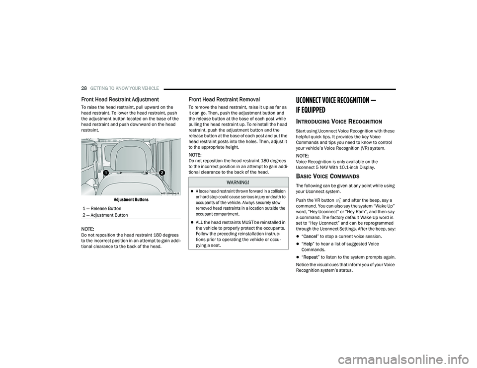
To raise the head restraint, pull upward on the
head restraint. To lower the head restraint, push
the adjustment button located on the base of the
head restraint and push downward on the head
restraint.
Adjustment Buttons
NOTE:Do not reposition the head restraint 180 degrees
to the incorrect position in an attempt to gain addi -
tional clearance to the back of the head.
Front Head Restraint Removal
To remove the head restraint, raise it up as far as
it can go. Then, push the adjustment button and
the release button at the base of each post while
pulling the head restraint up. To reinstall the head
restraint, push the adjustment button and the
release button at the base of each post and put the
head restraint posts into the holes. Then, adjust it
to the appropriate height.
NOTE:Do not reposition the head restraint 180 degrees
to the incorrect position in an attempt to gain addi -
tional clearance to the back of the head.
UCONNECT VOICE RECOGNITION —
IF EQUIPPED
INTRODUCING VOICE RECOGNITION
Start using Uconnect Voice Recognition with these
helpful quick tips. It provides the key Voice
Commands and tips you need to know to control
your vehicle’s Voice Recognition (VR) system.
NOTE:Voice Recognition is only available on the
Uconnect 5 NAV With 10.1-inch Display.
BASIC VOICE COMMANDS
The following can be given at any point while using
your Uconnect system.
Push the VR button and after the beep, say a
command. You can also say the system “Wake Up”
word, “Hey Uconnect” or “Hey Ram”, and then say
a command. The factory default Wake Up word is
set to “Hey Uconnect” and can be reprogrammed
through the Uconnect Settings. After the beep, say:
“ Cancel ” to stop a current voice session.
“Help ” to hear a list of suggested Voice
Commands.
“ Repeat ” to listen to the system prompts again.
Notice the visual cues that inform you of your Voice
Recognition system’s status.
1 — Release Button
2 — Adjustment Button
WARNING!
A loose head restraint thrown forward in a collision
or hard stop could cause serious injury or death to
occupants of the vehicle. Always securely stow
removed head restraints in a location outside the
occupant compartment.
ALL the head restraints MUST be reinstalled in
the vehicle to properly protect the occupants.
Follow the preceding reinstallation instruc
-
tions prior to operating the vehicle or occu -
pying a seat.
22_VF_OM_EN_USC_t.book Page 28
Page 31 of 268
GETTING TO KNOW YOUR VEHICLE29
GET STARTED
The VR button is used to activate/deactivate
your Voice Recognition system. You can also use
the system’s “Wake Up” word to activate voice
recognition. The “Wake Up” word can be set
through the Uconnect Settings Úpage 120.
Helpful hints for using Voice Recognition:
Reduce background noise. Wind noise and
passenger conversations are examples of noise
that may impact recognition.
Speak clearly at a normal pace and volume
while facing straight ahead.
Each time you give a Voice Command, first push the
VR button, wait until after the beep, then say your
Voice Command. Also, you can say the vehicle
“Wake Up” word to issue a Voice Command.
The available “Wake Up” words are “Hey Uconnect”
and “Hey Ram”.
You can interrupt the help message or system
prompts by pushing the VR button and saying a
Voice Command from the current category.
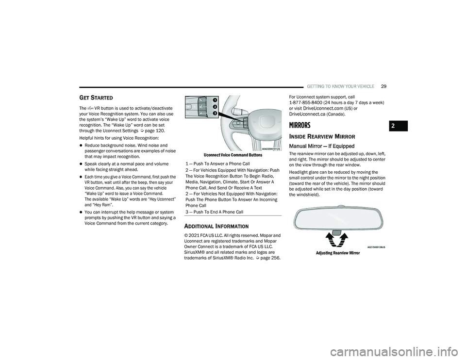
Uconnect Voice Command Buttons
ADDITIONAL INFORMATION
© 2021 FCA US LLC. All rights reserved. Mopar and
Uconnect are registered trademarks and Mopar
Owner Connect is a trademark of FCA US LLC.
SiriusXM® and all related marks and logos are
trademarks of SiriusXM® Radio Inc. Ú
page 256.For Uconnect system support, call
1-877-855-8400 (24 hours a day 7 days a week)
or visit
DriveUconnect.com (US) or DriveUconnect.ca (Canada).
MIRRORS
INSIDE REARVIEW MIRROR
Manual Mirror — If Equipped
The rearview mirror can be adjusted up, down, left,
and right. The mirror should be adjusted to center
on the view through the rear window.
Headlight glare can be reduced by moving the
small control under the mirror to the night position
(toward the rear of the vehicle). The mirror should
be adjusted while set in the day position (toward
the windshield).
Adjusting Rearview Mirror
1 — Push To Answer a Phone Call
2 — For Vehicles Equipped With Navigation: Push
The Voice Recognition Button To Begin Radio,
Media, Navigation, Climate, Start Or Answer A
Phone Call, And Send Or Receive A Text
2 — For Vehicles Not Equipped With Navigation:
Push The Phone Button To Answer An Incoming
Phone Call
3 — Push To End A Phone Call
2
22_VF_OM_EN_USC_t.book Page 29
Page 32 of 268
30GETTING TO KNOW YOUR VEHICLE
Digital Rearview Mirror — If Equipped
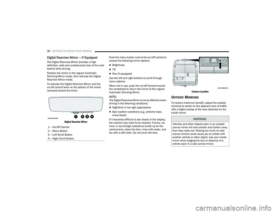
The Digital Rearview Mirror provides a high
definition, wide and unobstructed view of the road
behind while driving.
Position the mirror in the regular Automatic
Dimming Mirror mode, then activate the Digital
Rearview Mirror mode.
To activate the Digital Rearview Mirror, pull the
on/off control lever on the bottom of the mirror
rearward toward the driver.
Digital Rearview Mirror
Push the menu button next to the on/off control to
access the following mirror options:Brightness
Tilt
Pan (if equipped)
Use the left and right buttons to scroll through
menu options.
When not in use, push the on/off forward toward
the windshield to return the mirror to the regular
Automatic Dimming Mirror.
NOTE:The Digital Rearview Mirror is not as effective when
driving in the following conditions:
Nighttime in low light applications
Bad weather conditions (e.g. extreme haze,
snow/slush)
If it becomes difficult to see clearly in the display,
the camera may need to be cleaned. If snow, ice,
mud, or any foreign substance builds up on the
camera lens, clean the lens, rinse with water, and
dry with a soft cloth. Do not cover the lens.
Camera Location
OUTSIDE MIRRORS
To receive maximum benefit, adjust the outside
mirror(s) to center on the adjacent lane of traffic
with a slight overlap of the view obtained on the
inside mirror.
1 — On/Off Control
2 — Menu Button
3 — Left Scroll Button
4 — Right Scroll Button
WARNING!
Vehicles and other objects seen in an outside
convex mirror will look smaller and farther away
than they really are. Relying too much on side
convex mirrors could cause you to collide with
another vehicle or other object. Use your inside
mirror when judging the size or distance of a
vehicle seen in a side convex mirror.
22_VF_OM_EN_USC_t.book Page 30
Page 33 of 268
GETTING TO KNOW YOUR VEHICLE31
Outside Mirrors Folding Feature
All outside mirrors are hinged and may be folded
forward or rearward to avoid damage. The hinges
have three detent positions:
Full forward position
Full rearward position
Normal position
POWER MIRRORS — IF EQUIPPED
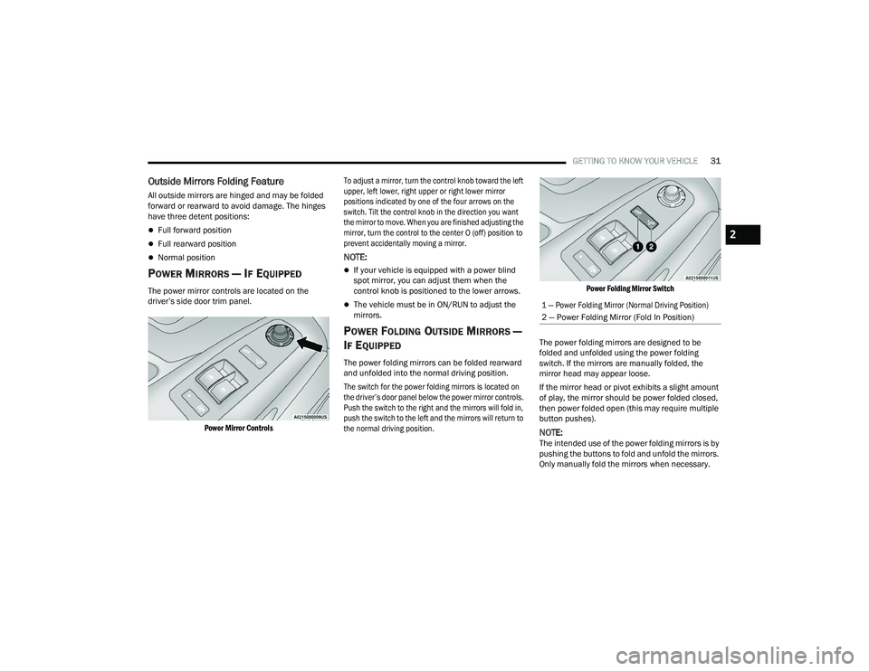
The power mirror controls are located on the
driver’s side door trim panel.
Power Mirror Controls
To adjust a mirror, turn the control knob toward the left
upper, left lower, right upper or right lower mirror
positions indicated by one of the four arrows on the
switch. Tilt the control knob in the direction you want
the mirror to move. When you are finished adjusting the
mirror, turn the control to the center O (off) position to
prevent accidentally moving a mirror.
NOTE:
If your vehicle is equipped with a power blind
spot mirror, you can adjust them when the
control knob is positioned to the lower arrows.
The vehicle must be in ON/RUN to adjust the
mirrors.
POWER FOLDING OUTSIDE MIRRORS —
I
F EQUIPPED
The power folding mirrors can be folded rearward
and unfolded into the normal driving position.
The switch for the power folding mirrors is located on
the driver’s door panel below the power mirror controls.
Push the switch to the right and the mirrors will fold in,
push the switch to the left and the mirrors will return to
the normal driving position.
Power Folding Mirror Switch
The power folding mirrors are designed to be
folded and unfolded using the power folding
switch. If the mirrors are manually folded, the
mirror head may appear loose.
If the mirror head or pivot exhibits a slight amount
of play, the mirror should be power folded closed,
then power folded open (this may require multiple
button pushes).
NOTE:The intended use of the power folding mirrors is by
pushing the buttons to fold and unfold the mirrors.
Only manually fold the mirrors when necessary.
1 — Power Folding Mirror (Normal Driving Position)
2 — Power Folding Mirror (Fold In Position)
2
22_VF_OM_EN_USC_t.book Page 31
Page 35 of 268
GETTING TO KNOW YOUR VEHICLE33
HIGH/LOW BEAM SWITCH
With the low beams activated, push the multifunction
lever toward the instrument panel to turn on the high
beams. The High Beam Indicator Light will illuminate in
the instrument cluster to indicated that the high beams
are on. Push the multifunction lever a second time to
switch the headlights back to low beam. When the
ignition is placed in the OFF position, both the high and
low beams will turn off.
AUTOMATIC HIGH BEAM HEADLAMP
C
ONTROL — IF EQUIPPED
The Automatic High Beam Headlamp Control
system provides increased forward lighting at night
by automating high beam control through the use
of a digital camera mounted on the windshield.
This camera detects vehicle specific light and
automatically switches from high beams to low
beams until the approaching vehicle is out of view.
NOTE:
The multifunction lever must be in the high
beam position in order for the Automatic High
Beam Headlamp Control to activate.
The Automatic High Beam Headlamp Control
can be turned on or off through Uconnect
Settings Ú page 120.
Broken, muddy, or obstructed headlights and
taillights of vehicles in the field of view will
cause headlights to remain on longer (closer to
the vehicle). Also, dirt, film, and other obstruc -
tions on the windshield or camera lens will
cause the system to function improperly.
When set to AUTO, the system automatically
turns the headlights on or off based on ambient
light levels.
FLASH-TO-PASS
You can signal another vehicle with your headlights
by lightly pulling the multifunction lever toward you.
This will cause the high beam headlights to turn on,
and remain on, until the lever is released.
AUTOMATIC HEADLIGHTS — IF EQUIPPED
To turn on the automatic headlights, turn the end
of the multifunction lever to the AUTO position. To
turn off the automatic headlights, turn the end of
the multifunction lever back to the O (off) position.
PARKING LIGHTS
These lights can be turned on, with the ignition in the
OFF position, by moving the end of the multifunction
lever to O (off) position and then to the headlight
position.
The indicator light in the instrument panel comes
on. The lights stay on until the next ignition cycle is
performed.
HEADLIGHT DELAY
When this feature is selected, the driver can
choose to have the headlights remain on for a
preset period of time after the engine is turned off.
Activation
To activate the delay feature, place the ignition in
the OFF position while the headlights are still on.
Then, rotate the multifunction lever to the O (off)
position within two minutes. The delay interval
begins when the headlight switch is turned from
O (off) to the low beam position. If the headlight
switch is in AUTO position and headlights were on
before the ignition is OFF, the delay interval begins
automatically.
Deactivation
The feature is disabled by turning on the
headlights, the parking lights or by placing the
ignition in the RUN position. If you shut off the
lights before the ignition is turned on, they will turn
off in the normal manner.
Headlights with ignition in the OFF position.
With the ignition in the OFF position, the headlights
can be switched on for a maximum time of
8 minutes. To turn on the headlights with the
ignition in the OFF position, turn the end of the
multifunction lever to the headlight position.
2
22_VF_OM_EN_USC_t.book Page 33