turn signal bulb RAM PROMASTER 2022 Owners Manual
[x] Cancel search | Manufacturer: RAM, Model Year: 2022, Model line: PROMASTER, Model: RAM PROMASTER 2022Pages: 268, PDF Size: 13.26 MB
Page 36 of 268

34GETTING TO KNOW YOUR VEHICLE
NOTE:If the headlight delay function is disabled in the
Uconnect Setting, when you put the ignition in the
OFF position with the multifunction lever already
set in the headlight position, the headlights remain
on for 8 minutes.
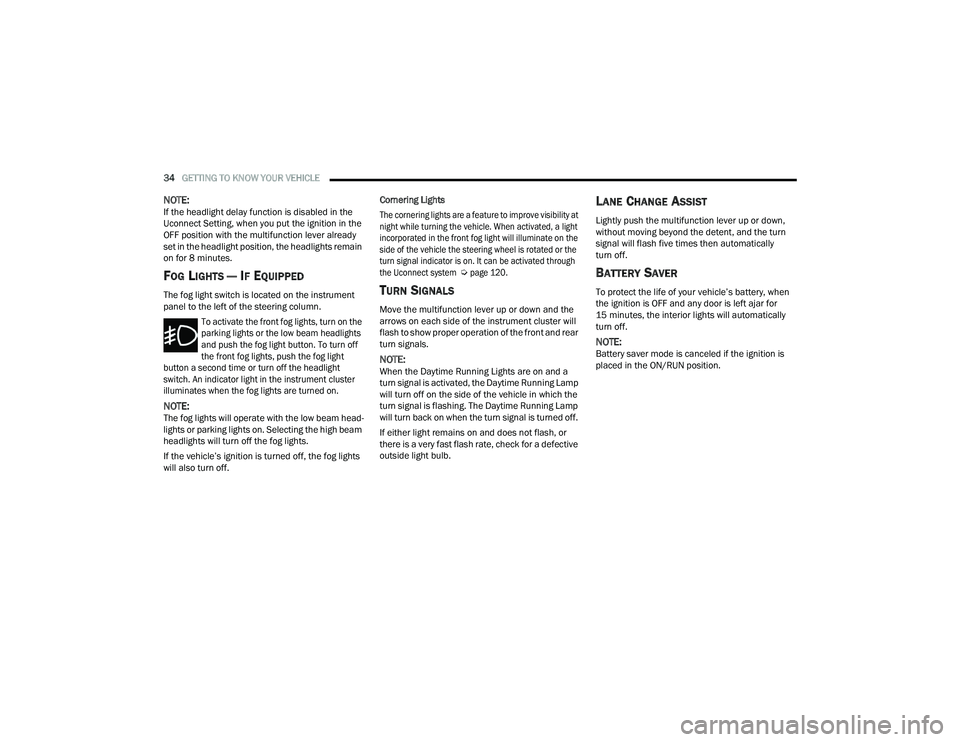
FOG LIGHTS — IF EQUIPPED
The fog light switch is located on the instrument
panel to the left of the steering column.
To activate the front fog lights, turn on the
parking lights or the low beam headlights
and push the fog light button. To turn off
the front fog lights, push the fog light
button a second time or turn off the headlight
switch. An indicator light in the instrument cluster
illuminates when the fog lights are turned on.
NOTE:The fog lights will operate with the low beam head -
lights or parking lights on. Selecting the high beam
headlights will turn off the fog lights.
If the vehicle’s ignition is turned off, the fog lights
will also turn off. Cornering Lights
The cornering lights are a feature to improve visibility at
night while turning the vehicle. When activated, a light
incorporated in the front fog light will illuminate on the
side of the vehicle the steering wheel is rotated or the
turn signal indicator is on. It can be activated through
the Uconnect system
Ú
page 120.
TURN SIGNALS
Move the multifunction lever up or down and the
arrows on each side of the instrument cluster will
flash to show proper operation of the front and rear
turn signals.
NOTE:When the Daytime Running Lights are on and a
turn signal is activated, the Daytime Running Lamp
will turn off on the side of the vehicle in which the
turn signal is flashing. The Daytime Running Lamp
will turn back on when the turn signal is turned off.
If either light remains on and does not flash, or
there is a very fast flash rate, check for a defective
outside light bulb.
LANE CHANGE ASSIST
Lightly push the multifunction lever up or down,
without moving beyond the detent, and the turn
signal will flash five times then automatically
turn off.
BATTERY SAVER
To protect the life of your vehicle’s battery, when
the ignition is OFF and any door is left ajar for
15 minutes, the interior lights will automatically
turn off.
NOTE:Battery saver mode is canceled if the ignition is
placed in the ON/RUN position.
22_VF_OM_EN_USC_t.book Page 34
Page 61 of 268

GETTING TO KNOW YOUR INSTRUMENT PANEL59
WARNING LIGHTS AND MESSAGES
The warning/indicator lights will illuminate in the
instrument panel together with a dedicated message
and/or acoustic signal when applicable. These
indications are indicative and precautionary and as
such must not be considered as exhaustive and/or
alternative to the information contained in the Owner’s
Manual, which you are advised to read carefully in all
cases. Always refer to the information in this chapter in
the event of a failure indication. All active telltales will
display first if applicable. The system check menu may
appear different based upon equipment options and
current vehicle status. Some telltales are optional and
may not appear.
RED WARNING LIGHTS
Air Bag Warning Light
This light will turn on for four to eight seconds
as a bulb check when the ignition is placed in
the ON/RUN or MAR/ON/RUN position. If the
light is either not on during startup, stays on,
or turns on while driving, have the system inspected at
an authorized dealer as soon as possible. This light will
illuminate with a single chime when a fault with the
Air Bag Warning Light has been detected, it will stay
on until the fault is cleared. If the light comes on
intermittently or remains on while driving, have an
authorized dealer service the vehicle immediately.
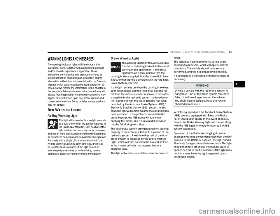
Brake Warning Light
This warning light monitors various brake
functions, including brake fluid level and
parking brake application. If the brake
light turns on it may indicate that the
parking brake is applied, that the brake fluid level
is low, or that there is a problem with the Anti-Lock
Brake System reservoir.
If the light remains on when the parking brake has
been disengaged, and the fluid level is at the full
mark on the master cylinder reservoir, it indicates
a possible brake hydraulic system malfunction or
that a problem with the Brake Booster has been
detected by the Anti-Lock Brake System (ABS) /
Electronic Stability Control (ESC) system. In this
case, the light will remain on until the condition has
been corrected. If the problem is related to the
brake booster, the ABS pump will run when
applying the brake, and a brake pedal pulsation
may be felt during each stop.
The dual brake system provides a reserve braking
capacity in the event of a failure to a portion of the
hydraulic system. A leak in either half of the dual
brake system is indicated by the Brake Warning
Light, which will turn on when the brake fluid level
in the master cylinder has dropped below a
specified level.
The light will remain on until the cause is corrected.
NOTE:The light may flash momentarily during sharp
cornering maneuvers, which change fluid level
conditions. The vehicle should have service
performed, and the brake fluid level checked.
If brake failure is indicated, immediate repair is
necessary.
Vehicles equipped with the Anti-Lock Brake System
(ABS) are also equipped with Electronic Brake
Force Distribution (EBD). In the event of an EBD
failure, the Brake Warning Light will turn on along
with the ABS Light. Immediate repair to the ABS
system is required.
Operation of the Brake Warning Light can be
checked by turning the ignition switch from the OFF
position to the ON/RUN position. The light should
illuminate for approximately two seconds. The light
should then turn off unless the parking brake is
applied or a brake fault is detected. If the light does
not illuminate, have the light inspected by an
authorized dealer.
WARNING!
Driving a vehicle with the red brake light on is
dangerous. Part of the brake system may have
failed. It will take longer to stop the vehicle.
You could have a collision. Have the vehicle
checked immediately.
3
22_VF_OM_EN_USC_t.book Page 59
Page 65 of 268

GETTING TO KNOW YOUR INSTRUMENT PANEL63
Engine Check/Malfunction Indicator (MIL)
Warning Light
The Engine Check/Malfunction Indicator
Light (MIL) is a part of an Onboard
Diagnostic System called OBD II that
monitors engine and automatic
transmission control systems. This warning light
will illuminate when the ignition is in the ON/RUN
position before engine start. If the bulb does not
come on when turning the ignition switch from OFF
to ON/RUN, have the condition checked promptly.
Certain conditions, such as a loose or missing gas
cap, poor quality fuel, etc., may illuminate the light
after engine start. The vehicle should be serviced if
the light stays on through several typical driving
styles. In most situations, the vehicle will drive
normally and will not require towing.
When the engine is running, the MIL may flash to
alert serious conditions that could lead to immediate
loss of power or severe catalytic converter damage.
The vehicle should be serviced by an authorized dealer
as soon as possible if this occurs.
Service Active Lane Management Warning
Light — If Equipped
This warning light will illuminate when the
Active Lane Management system is not
operating and requires service. Please
see an authorized dealer.
Service Forward Collision Warning (FCW)
Light — If Equipped
This warning light will illuminate to
indicate a fault in the FCW System.
Contact an authorized dealer for service.
Service Required/Call For Service Warning
Light
This warning light will illuminate when
service is needed. A pop-up will appear in
the display to signal the need for service.
Contact an authorized dealer as soon as
possible.
Tire Pressure Monitoring System (TPMS)
Warning Light
The warning light switches on and a message
is displayed to indicate that the tire pressure
is lower than the recommended value and/
or that slow pressure loss is occurring. In
these cases, optimal tire duration and fuel
consumption may not be guaranteed.
Should one or more tires be in the condition
mentioned above, the display will show the
indications corresponding to each tire.
WARNING!
A malfunctioning catalytic converter, as referenced
above, can reach higher temperatures than in
normal operating conditions. This can cause a fire if
you drive slowly or park over flammable substances
such as dry plants, wood, cardboard, etc. This could
result in death or serious injury to the driver,
occupants or others.
CAUTION!
Prolonged driving with the Malfunction Indicator
Light (MIL) on could cause damage to the vehicle
control system. It also could affect fuel economy and
driveability. If the MIL is flashing, severe catalytic
converter damage and power loss will soon occur.
Immediate service is required.
3
22_VF_OM_EN_USC_t.book Page 63
Page 67 of 268

GETTING TO KNOW YOUR INSTRUMENT PANEL65
Transmission Temperature Warning Light
This warning light will illuminate to warn
of a high transmission fluid temperature.
This may occur with strenuous usage
such as trailer towing. If this light turns
on, stop the vehicle and run the engine at idle or
slightly faster, with the transmission in PARK (P) or
NEUTRAL (N), until the light turns off. Once the light
turns off, you may continue to drive normally.
YELLOW INDICATOR LIGHTS
Forward Collision Warning (FCW) OFF
Indicator Light — If Equipped
This indicator light will illuminate when
you switch FCW off or when driving
conditions obscure the sensor with snow,
heavy rain, or sun.
TOW/HAUL Indicator Light
This indicator light will illuminate when
TOW/HAUL mode is selected
Ú
page 110.
Keyless System Failure Light
The telltale will illuminate in the event of
keyless system failure.
Contact an authorized dealer as soon as possible.
Rain Sensor Failure Light
The telltale will illuminate in the case of
failure of the automatic windshield wiper.
Contact an authorized dealer as soon as
possible.
Exterior Lights Failure Light
The telltale will illuminate to indicate a
failure on the following lights: Daytime
Running Lights (DRLs) / parking lights /
trailer turn signal indicators (if present) /
trailer lights (if present) / side lights / turn signal
indicators / rear fog light / reversing light / brake
lights / license plate lights.
The failure may be caused by a blown bulb, a blown
protection fuse, or an interruption of the electrical
connection. Replace the bulb or the relevant fuse.
Contact an authorized dealer.
Fuel Cutoff Failure Light — If Equipped
This light will illuminate if there is a fuel
cutoff failure. If this light illuminates, take
it to an authorized dealer and have them
inspect it.
GREEN INDICATOR LIGHTS
Active Lane Management Indicator Light —
If Equipped
The Active Lane Management indicator light
illuminates solid green when both lane
markings have been detected and the
system is “armed” and ready to provide
visual and torque warnings if an unintentional lane
departure occurs
Ú
page 102.
WARNING!
If you continue operating the vehicle when the
Transmission Temperature Warning Light is
illuminated you could cause the fluid to boil over,
come in contact with hot engine or exhaust
components and cause a fire.
CAUTION!
Continuous driving with the Transmission
Temperature Warning Light illuminated will
eventually cause severe transmission damage
or transmission failure.
3
22_VF_OM_EN_USC_t.book Page 65
Page 68 of 268

66GETTING TO KNOW YOUR INSTRUMENT PANEL
Active Speed Limiter Set Indicator Light —
If Equipped With A Premium Instrument
Cluster
This indicator light will illuminate when
the Active Speed Limiter is on and set to
a specific speed Úpage 79.
Automatic High Beam Indicator Light —
If Equipped
This indicator shows that the automatic
high beam headlights are on Úpage 32.
Cruise Control Indicator Light —
If Equipped
This indicator light will illuminate when the
cruise control is activated
Ú
page 80.
NOTE:There will be no change in the indicator light when
the desired speed is set.
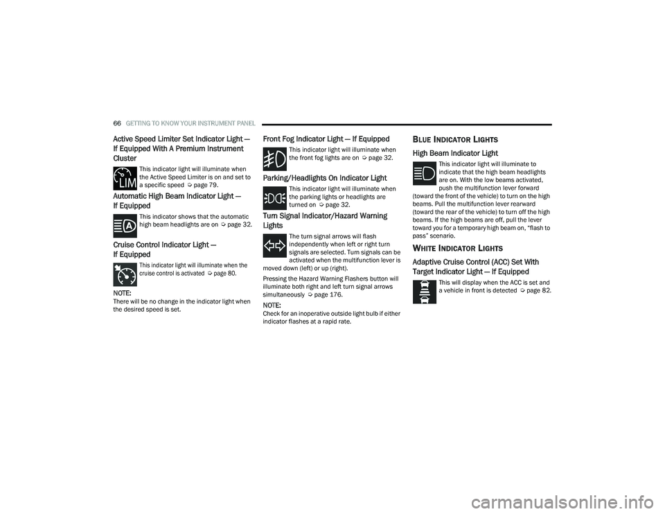
Front Fog Indicator Light — If Equipped
This indicator light will illuminate when
the front fog lights are on Ú page 32.
Parking/Headlights On Indicator Light
This indicator light will illuminate when
the parking lights or headlights are
turned on Úpage 32.
Turn Signal Indicator/Hazard Warning
Lights
The turn signal arrows will flash
independently when left or right turn
signals are selected. Turn signals can be
activated when the multifunction lever is
moved down (left) or up (right).
Pressing the Hazard Warning Flashers button will
illuminate both right and left turn signal arrows
simultaneously Ú page 176.
NOTE:Check for an inoperative outside light bulb if either
indicator flashes at a rapid rate.
BLUE INDICATOR LIGHTS
High Beam Indicator Light
This indicator light will illuminate to
indicate that the high beam headlights
are on. With the low beams activated,
push the multifunction lever forward
(toward the front of the vehicle) to turn on the high
beams. Pull the multifunction lever rearward
(toward the rear of the vehicle) to turn off the high
beams. If the high beams are off, pull the lever
toward you for a temporary high beam on, “flash to
pass” scenario.
WHITE INDICATOR LIGHTS
Adaptive Cruise Control (ACC) Set With
Target Indicator Light — If Equipped
This will display when the ACC is set and
a vehicle in front is detected Ú page 82.
22_VF_OM_EN_USC_t.book Page 66
Page 223 of 268

SERVICING AND MAINTENANCE221
Exterior Bulbs
Bulb Name Bulb Number
Front Low and High Beam Headlamp H7SLL
Front Park/Turn Signal Lamps 7444NA
Daytime Running Lamps (If Equipped) 7440
Front Side Marker Lamps W3W
Rear Tail/Stop Lamps 7443
Rear Turn Signal Lamps 7440NA
Rear Backup Lamps 921
Rear Side Marker Lamps W3W
Front Fog Lamps H11
License Plate Lamps C5W
Front Roof Lamps WY5W
Rear Roof Lamps W3W
NOTE:Numbers refer to commercial bulb types that can be purchased from an authorized dealer. If a bulb needs to be replaced, visit an authorized dealer.8
22_VF_OM_EN_USC_t.book Page 221
Page 224 of 268

222SERVICING AND MAINTENANCE
Replacing Exterior Bulbs
HEADLAMPS LOW BEAM AND HIGH BEAM
See the following steps to replace:
1. Remove one retaining screw on the lower
headlamp filler panel. Remove filler panel.
2. Remove two retaining screws on the upper headlamp filler panel. Remove filler panel.
3. Remove one upper retaining screw from the headlamp housing.
4. Remove two lower retaining screws from the headlamp housing.
5. Pull Headlamp forward, disconnect harness electrical connector and remove the headlamp
assembly from vehicle.
6. Remove appropriate plastic cap from the back of the headlamp housing.
7. Push down on the upper portion of the socket.
8. Pull the socket outward from reflector.
9. Pull bulb outward from socket.
10. Install new bulb.
11. Push socket back into reflector until it locks back into place.
12. Install access cap.
13. Carefully reinstall headlamp in the same position on the vehicle, so as not to affect
headlamp aiming. 14. Install one upper retaining screw on the
headlamp housing.
15. Install two lower retaining screws on the headlamp housing.
16. Carefully reinstall the lower headlamp filler panel and one retaining screw.
17. Carefully reinstall the upper headlamp filler panel and two retaining screws.
FRONT TURN SIGNAL/PARKING LAMPS
See the following steps to replace:
1. Remove one retaining screw on the lower headlamp filler panel. Remove filler panel.
2. Remove two retaining screws on the upper headlamp filler panel. Remove filler panel.
3. Remove one upper retaining screw from the headlamp housing.
4. Remove two lower retaining screws from the headlamp housing.
5. Pull Headlamp forward, disconnect the harness electrical connector and remove the
headlamp assembly from vehicle.
6. Rotate the bulb counterclockwise and remove.
7. Install the bulb into socket, and rotate bulb/ socket clockwise into lamp locking it in place. 8. Carefully reinstall headlamp in the same
position on the vehicle, so as not to affect
headlamp aiming.
9. Install the one upper retaining screw on headlamp housing.
10. Install the two lower retaining screws on headlamp housing.
11. Carefully reinstall the lower headlamp filler panel and one retaining screw.
12. Carefully reinstall the upper headlamp filler panel and two retaining screws.
DAYTIME RUNNING LAMP (DRL)/FRONT SIDE
MARKER LAMP
See the following steps to replace:
1. Remove one retaining screw on the lower headlamp filler panel. Remove filler panel.
2. Remove two retaining screws on the upper headlamp filler panel. Remove filler panel.
3. Remove one upper retaining screw from the headlamp housing.
4. Remove two lower retaining screws from the headlamp housing.
5. Pull Headlamp forward, disconnect the harness electrical connector and remove the
headlamp assembly from vehicle.
22_VF_OM_EN_USC_t.book Page 222
Page 225 of 268

SERVICING AND MAINTENANCE223
6. Remove the (DRL), side marker bulb by pulling straight out.
7. Replace lamp as required and lock in place.
8. Reinstall plastic cap.
9. Carefully reinstall headlamp in the same position on the vehicle, as not to affect
headlamp aiming.
10. Install the one upper retaining screw on the headlamp housing.
11. Install the two lower retaining screws on the headlamp housing.
12. Carefully reinstall the lower headlamp filler panel and one retaining screw.
13. Carefully reinstall the upper headlamp filler panel and two retaining screws.
FRONT FOG LAMPS
See the following steps to replace:
1. Turn front wheels inboard to access cover in wheel liner.
2. Open the cover on the front of the wheel liner.
3. Remove connection and replace the bulb.
4. Connect the wire and rotate bulb/socket clockwise into lamp locking it in place.
5. Reinstall the plastic cap and close the cover on the wheel liner.
FRONT, REAR ROOF LAMPS
See the following steps to replace:
1. Remove two screw and remove the lamp assembly.
2. Remove the socket bulb by turning counter -
clockwise.
3. Remove bulb and replace as needed.
4. Reinstall the bulb socket and rotate clockwise to lock in place.
5. Reinstall lamp.
REAR TAIL, STOP, BACKUP, TURN SIGNAL AND
REAR SIDE MARKER LAMPS
See the following steps to replace:
1. Open rear doors.
2. Remove the seven (7) fasteners from the rear access cover and remove cover to gain access
to the tail lamp assembly fasteners.
Rear Access Cover
3. Remove the two (2) 17 mm tail lamp assembly fasteners.
4. Disconnect the tail lamp harness connector and remove tail light assembly from the
vehicle.
5. Remove the tail/stop, turn signal, backup and rear side marker bulb/socket by rotating
counterclockwise.
6. Remove the bulb and replace as needed.
7. Reinstall bulb/socket and rotate clockwise to lock in place.
8. Reinstall lamp.
8
22_VF_OM_EN_USC_t.book Page 223
Page 264 of 268

262 Power Inverter
........................................................ 46Mirrors......................................................... 31Outlet (Auxiliary Electrical Outlet)................ 45Steering....................................................... 78Windows...................................................... 48Pregnant Women And Seat Belts...................159Preparation For Jacking................................. 180
R
Radial Ply Tires.............................................. 234Radiator Cap (Coolant Pressure Cap)............ 210RadioSound Setting............................................ 132Radio Operation............................................ 136Rain Sensitive Wiper System........................... 38Rear Camera....................................... 105, 106Rear Cross Path............................................. 144Rear ParkSense System.................................. 96Rearview Mirror............................................... 29Recreational Towing...................................... 116Reformulated Gasoline.................................. 249Refrigerant.................................................... 206Release, Hood................................................. 49Reminder, Seat Belt...................................... 155Remote Keyless EntryProgramming Additional Key Fobs.............. 15Remote StartingExit Remote Start Mode.............................. 18Remote Starting System.................................. 17
Replacement Bulbs...................................... 220Replacement Keys........................................... 15Replacement Tires........................................ 236Reporting Safety Defects.............................. 255Restraints, Child........................................... 168Restraints, Head.............................................. 27Rotation, Tires.............................................. 241
S
Safety Checks Inside Vehicle........................ 173Safety Checks Outside Vehicle..................... 174Safety Defects, Reporting............................. 255Safety Information, Tire................................ 225Safety Tips.................................................... 172Safety, Exhaust Gas...................................... 175Schedule, Maintenance................................ 198Seat Belts............................................ 154, 173Adjustable Shoulder Belt.......................... 158Adjustable Upper Shoulder Anchorage..... 158Adjustable Upper Shoulder Belt Anchorage............................................ 158Automatic Locking Retractor (ALR)........... 159Child Restraints........................................ 168Energy Management Feature................... 159Front Seat............................... 154, 155, 157Inspection................................................. 173Lap/Shoulder Belt Operation.................... 157Lap/Shoulder Belt Untwisting................... 158Lap/Shoulder Belts.................................. 155
Operating Instructions.............................. 157Pregnant Women...................................... 159Rear Seat.................................................. 155Reminder.................................................. 155Untwisting Procedure................................ 158Seat Belts Maintenance................................ 245Seats................................................................23Adjustment..................................................23Heated.........................................................26Rear Folding................................................23Tilting...........................................................23Security Alarm...........................................20, 61Selection Of Coolant (Antifreeze).................. 251Sentry Key (Immobilizer)..................................16Service Assistance........................................ 253Service Contract............................................ 254Service Manuals........................................... 255SettingsPersonal................................................... 120Shift Lever Override...................................... 195Shoulder Belts.............................................. 155Signals, Turn................................................. 174Snow Chains (Tire Chains)............................ 240Snow Tires.................................................... 237Spare Tires........................................... 237, 238Speed Limiter, Active.......................................79
22_VF_OM_EN_USC_t.book Page 262