Brake service RAM PROMASTER 2023 Owner's Manual
[x] Cancel search | Manufacturer: RAM, Model Year: 2023, Model line: PROMASTER, Model: RAM PROMASTER 2023Pages: 296, PDF Size: 12.31 MB
Page 209 of 296
IN CASE OF EMERGENCY207
If the tire inflates to the recommended pressure or
is at least 26 psi (1.8 bar) within 15 minutes:
NOTE:If the tire becomes overinflated, push the Deflation
Button to reduce the tire pressure to the recom -
mended inflation pressure before continuing.
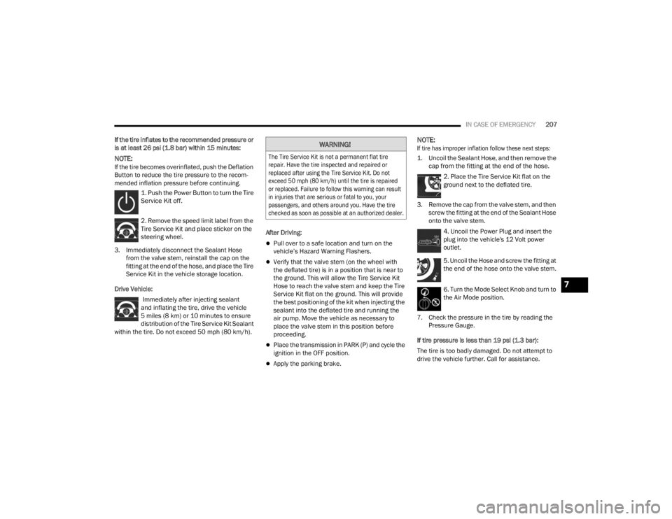
1. Push the Power Button to turn the Tire
Service Kit off.
2. Remove the speed limit label from the
Tire Service Kit and place sticker on the
steering wheel.
3. Immediately disconnect the Sealant Hose from the valve stem, reinstall the cap on the
fitting at the end of the hose, and place the Tire
Service Kit in the vehicle storage location.
Drive Vehicle: Immediately after injecting sealant
and inflating the tire, drive the vehicle
5 miles (8 km) or 10 minutes to ensure distribution of the Tire Service Kit Sealant
within the tire. Do not exceed 50 mph (80 km/h). After Driving:
Pull over to a safe location and turn on the
vehicle’s Hazard Warning Flashers.
Verify that the valve stem (on the wheel with
the deflated tire) is in a position that is near to
the ground. This will allow the Tire Service Kit
Hose to reach the valve stem and keep the Tire
Service Kit flat on the ground. This will provide
the best positioning of the kit when injecting the
sealant into the deflated tire and running the
air pump. Move the vehicle as necessary to
place the valve stem in this position before
proceeding.
Place the transmission in PARK (P) and cycle the
ignition in the OFF position.
Apply the parking brake.
NOTE:
If tire has improper inflation follow these next steps:
1. Uncoil the Sealant Hose, and then remove the
cap from the fitting at the end of the hose.
2. Place the Tire Service Kit flat on the
ground next to the deflated tire.
3. Remove the cap from the valve stem, and then screw the fitting at the end of the Sealant Hose
onto the valve stem.
4. Uncoil the Power Plug and insert the
plug into the vehicle's 12 Volt power
outlet.
5. Uncoil the Hose and screw the fitting at
the end of the hose onto the valve stem.
6. Turn the Mode Select Knob and turn to
the Air Mode position.
7. Check the pressure in the tire by reading the Pressure Gauge.
If tire pressure is less than 19 psi (1.3 bar):
The tire is too badly damaged. Do not attempt to
drive the vehicle further. Call for assistance.WARNING!
The Tire Service Kit is not a permanent flat tire
repair. Have the tire inspected and repaired or
replaced after using the Tire Service Kit. Do not
exceed 50 mph (80 km/h) until the tire is repaired
or replaced. Failure to follow this warning can result
in injuries that are serious or fatal to you, your
passengers, and others around you. Have the tire
checked as soon as possible at an authorized dealer.
7
23_VF_OM_EN_USC_t.book Page 207
Page 213 of 296
IN CASE OF EMERGENCY211
SEALING A TIRE WITH TIRE SERVICE KIT
(A) Whenever You Stop To Use Tire Service Kit:
1. Pull over to a safe location and turn on the
vehicle’s Hazard Warning Flashers.
2. Verify that the valve stem (on the wheel with the deflated tire) is in a position that is near to
the ground. This will allow the Tire Service Kit
Hoses (3) and (5) to reach the valve stem and
keep the Tire Service Kit flat on the ground. This will provide the best positioning of the kit
when injecting the sealant into the deflated
tire and running the air pump. Move the
vehicle as necessary to place the valve stem in
this position before proceeding.
3. Place the transmission in PARK (P) (auto transmission) or in Gear (manual transmission)
and place the ignition in the OFF position.
4. Apply the parking brake.
(B) Setting Up To Use Tire Service Kit:
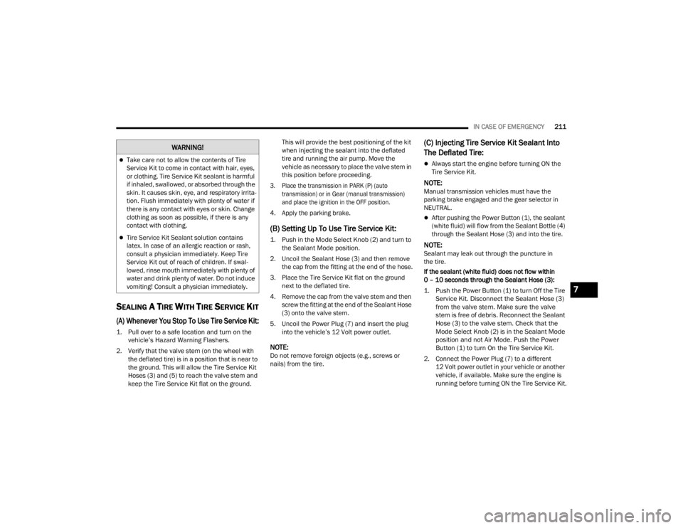
1. Push in the Mode Select Knob (2) and turn to the Sealant Mode position.
2. Uncoil the Sealant Hose (3) and then remove the cap from the fitting at the end of the hose.
3. Place the Tire Service Kit flat on the ground next to the deflated tire.
4. Remove the cap from the valve stem and then screw the fitting at the end of the Sealant Hose
(3) onto the valve stem.
5. Uncoil the Power Plug (7) and insert the plug into the vehicle’s 12 Volt power outlet.
NOTE:Do not remove foreign objects (e.g., screws or
nails) from the tire.
(C) Injecting Tire Service Kit Sealant Into
The Deflated Tire:
Always start the engine before turning ON the
Tire Service Kit.
NOTE:Manual transmission vehicles must have the
parking brake engaged and the gear selector in
NEUTRAL.
After pushing the Power Button (1), the sealant
(white fluid) will flow from the Sealant Bottle (4)
through the Sealant Hose (3) and into the tire.
NOTE:Sealant may leak out through the puncture in
the tire.
If the sealant (white fluid) does not flow within
0 – 10 seconds through the Sealant Hose (3):
1. Push the Power Button (1) to turn Off the Tire Service Kit. Disconnect the Sealant Hose (3)
from the valve stem. Make sure the valve
stem is free of debris. Reconnect the Sealant
Hose (3) to the valve stem. Check that the
Mode Select Knob (2) is in the Sealant Mode
position and not Air Mode. Push the Power
Button (1) to turn On the Tire Service Kit.
2. Connect the Power Plug (7) to a different 12 Volt power outlet in your vehicle or another
vehicle, if available. Make sure the engine is
running before turning ON the Tire Service Kit.
Take care not to allow the contents of Tire
Service Kit to come in contact with hair, eyes,
or clothing. Tire Service Kit sealant is harmful
if inhaled, swallowed, or absorbed through the
skin. It causes skin, eye, and respiratory irrita -
tion. Flush immediately with plenty of water if
there is any contact with eyes or skin. Change
clothing as soon as possible, if there is any
contact with clothing.
Tire Service Kit Sealant solution contains
latex. In case of an allergic reaction or rash,
consult a physician immediately. Keep Tire
Service Kit out of reach of children. If swal -
lowed, rinse mouth immediately with plenty of
water and drink plenty of water. Do not induce
vomiting! Consult a physician immediately.
WARNING!
7
23_VF_OM_EN_USC_t.book Page 211
Page 218 of 296

216IN CASE OF EMERGENCY
4. Disconnect the opposite end of the positive (+)
jumper cable from the remote positive (+) post
of the discharged vehicle, and reinstall the
protective cap.
5. Close the cover of the Front Power Distribution Center.
If frequent jump starting is required to start your
vehicle you should have the battery and charging
system inspected at an authorized dealer.
BATTERY LOCATION
There are two remote jump starting posts under
the hood which is the recommended jump start
location. If access to the battery is needed, an
access panel on the driver’s side floor will allow for
battery access.
Battery Access Panel
Battery Location
IF YOUR ENGINE OVERHEATS
If the vehicle is overheating, it will need to be
serviced by an authorized dealer.
In any of the following situations, you can reduce
the potential for overheating by taking the
appropriate action.
On the highways — slow down.
In city traffic — while stopped, place the trans -
mission in NEUTRAL (N), but do not increase the
engine idle speed while preventing vehicle
motion with the brakes.
NOTE:There are steps that you can take to slow down an
impending overheat condition:
If your Air Conditioner (A/C) is on, turn it off.
The A/C system adds heat to the engine cooling
system and turning the A/C off can help remove
this heat.
You can also turn the temperature control to
maximum heat, the mode control to floor and
the blower control to high. This allows the heater
core to act as a supplement to the radiator and
aids in removing heat from the engine cooling
system.
CAUTION!
Accessories plugged into the vehicle power
outlets draw power from the vehicle’s battery,
even when not in use (i.e., cellular devices, etc.).
Eventually, if plugged in long enough without
engine operation, the vehicle’s battery will
discharge sufficiently to degrade battery life
and/or prevent the engine from starting.
23_VF_OM_EN_USC_t.book Page 216
Page 219 of 296

IN CASE OF EMERGENCY217
GEAR SELECTOR OVERRIDE
If a malfunction occurs and the gear selector
cannot be moved out of the PARK (P) position, you
can use the following procedure to temporarily
move the gear selector:
1. Turn the engine OFF.
2. Firmly apply the parking brake.
3. Using a small screwdriver or similar tool,
remove the shifter boot material of the gear
selector by pulling up to carefully separate the
gear selector bezel and boot assembly from
the console.
Shifter Boot And Bezel
4. Press and maintain firm pressure on the brake
pedal.
5. Insert the screwdriver or similar tool into the gear selector override release and push down
while depressing the shifter button at the
same time.
Gear Selector Override Release Lever
6. Move the gear selector to the NEUTRAL (N) position.
7. The vehicle may then be started in NEUTRAL.
8. Reinstall the shifter boot and bezel.
WARNING!
You or others can be badly burned by hot engine
coolant (antifreeze) or steam from your radiator.
If you see or hear steam coming from under the
hood, do not open the hood until the radiator
has had time to cool. Never try to open a cooling
system pressure cap when the radiator or
coolant bottle is hot.
CAUTION!
Driving with a hot cooling system could damage
your vehicle. If the temperature gauge reads
HOT (H), pull over and stop the vehicle. Idle the
vehicle with the air conditioner turned off until
the pointer drops back into the normal range.
If the pointer remains on HOT (H), and you
hear continuous chimes, turn the engine off
immediately and call for service.
7
23_VF_OM_EN_USC_t.book Page 217
Page 221 of 296
IN CASE OF EMERGENCY219
TOWING A DISABLED VEHICLE
This section describes procedures for towing a disabled vehicle using a commercial towing service.
Proper towing or lifting equipment is required to
prevent damage to your vehicle. Use only tow bars
and other equipment designed for this purpose,
following equipment manufacturer’s instructions.
Use of safety chains is mandatory. Attach a tow bar
or other towing device to main structural members
of the vehicle, not to fascia/bumper or associated
brackets. State and local laws regarding vehicles
under tow must be observed.
NOTE:
You must ensure that the Auto Park Brake
Úpage 78 feature is disabled before towing this
vehicle to avoid inadvertent Electric Park Brake
engagement. The Auto Park Brake feature is
enabled or disabled via the customer program -
mable features in the Uconnect Settings.
Vehicles with a discharged battery, or total elec -
trical failure when the Electric Park Brake (EPB)
is engaged, will need a wheel dolly or jack to
raise the rear wheels off the ground when
moving the vehicle onto a flatbed.
The Safehold feature will engage the Electric
Park Brake whenever the driver's door is
opened (if the battery is connected, ignition is
ON, transmission is not in PARK, and brake
pedal is released). If you are towing this vehicle
with the ignition in the ON/RUN mode, you must
manually disable the Electric Park Brake each
time the driver's door is opened by pressing the
brake pedal and then releasing the EPB. If you must use the accessories (wipers,
defrosters, etc.) while being towed, the ignition
must be in the ON/RUN mode.
If the key fob is unavailable or the vehicle's battery
is discharged, for instructions on shifting the
automatic transmission out of PARK (P) for
towing Ú
page 217.
Towing Condition Wheels OFF the Ground Automatic Transmission
Flat Tow NONENOT ALLOWED
Dolly Tow Front
OK
Rear NOT ALLOWED
On Trailer ALLOK
NOTE:When towing your vehicle, always follow applicable state and provincial laws. Contact state and provincial Highway Safety offices for additional details.
CAUTION!
Do not use sling type equipment when towing.
Vehicle damage may occur.
When securing the vehicle to a flat bed truck,
do not attach to front or rear suspension
components. Damage to your vehicle may
result from improper towing.
7
23_VF_OM_EN_USC_t.book Page 219
Page 223 of 296
221
SERVICING AND MAINTENANCE
SCHEDULED SERVICING
Your vehicle is equipped with an automatic oil
change indicator system. The oil change indicator
system will remind you that it is time to take your
vehicle in for scheduled maintenance.
Based on engine operation conditions, the oil change
indicator message will illuminate in the instrument
cluster. This means that service is required for your
vehicle. Operating conditions such as frequent
short-trips, trailer tow, and extremely hot or cold
ambient temperatures will influence when the “Oil
Change Required” message is displayed. Have the
vehicle serviced as soon as possible, within the next
500 miles (805 km).
An authorized dealer will reset the oil change
indicator message after completing the scheduled
oil change. If a scheduled oil change is performed
by someone other than an authorized dealer, the
message can be reset by referring to the steps
described under Instrument Cluster Display
Ú
page 57.
NOTE:Under no circumstances should oil change
intervals exceed 10,000 miles (16,000 km),
12 months or 350 hours of engine run time,
whichever comes first. The 350 hours of engine
run or idle time is generally only a concern for fleet
customers. Once A Month Or Before A Long Trip:
Check engine oil level
Check windshield washer fluid level
Check the tire pressures and look for unusual
wear or damage. Rotate at the first sign of irreg
-
ular wear, even if it occurs before the oil indi -
cator system turns on
Check the fluid levels of the coolant reservoir,
and brake master cylinder and fill as needed
Check function of all interior and exterior lights
8
23_VF_OM_EN_USC_t.book Page 221
Page 226 of 296
224SERVICING AND MAINTENANCE
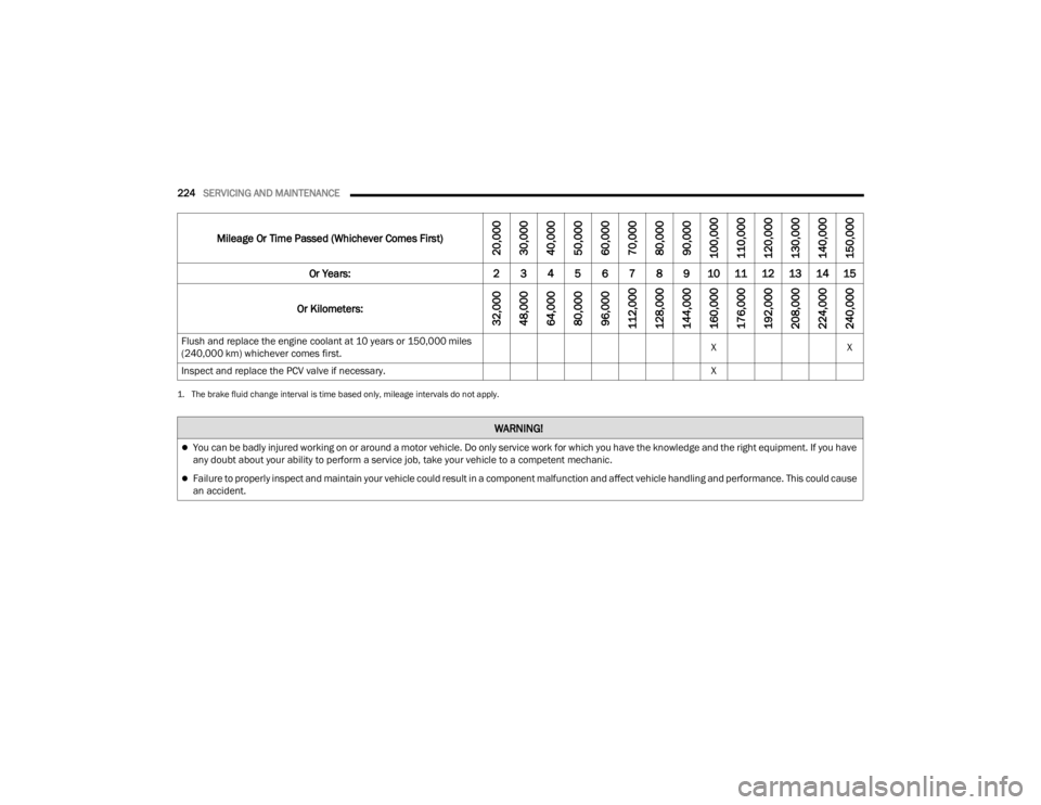
Flush and replace the engine coolant at 10 years or 150,000 miles
(240,000 km) whichever comes first. X
X
Inspect and replace the PCV valve if necessary. X
1. The brake fluid change interval is time based only, mileage intervals do not apply.
WARNING!
You can be badly injured working on or around a motor vehicle. Do only service work for which you have the knowledge and the right equipment. If you have
any doubt about your ability to perform a service job, take your vehicle to a competent mechanic.
Failure to properly inspect and maintain your vehicle could result in a component malfunction and affect vehicle handling and performance. This could cause
an accident.
Mileage Or Time Passed (Whichever Comes First)
20,000
30,000
40,000
50,000
60,000
70,000
80,000
90,000
100,000
110,000
120,000
130,000
140,000
150,000
Or Years: 2 3 4 5 6 7 8 9 10 11 12 13 14 15
Or Kilometers:
32,000
48,000
64,000
80,000
96,000
112,000
128,000
144,000
160,000
176,000
192,000
208,000
224,000
240,000
23_VF_OM_EN_USC_t.book Page 224
Page 237 of 296

SERVICING AND MAINTENANCE235
If an examination of your engine compartment
shows no evidence of radiator or hose leaks, the
vehicle may be safely driven. The vapor will soon
dissipate.
Do not overfill the coolant expansion bottle.
Check the coolant freeze point in the radiator
and in the coolant expansion bottle. If engine
coolant needs to be added, the contents of the
coolant expansion bottle must also be protected
against freezing.
If frequent engine coolant additions are
required, the cooling system should be pressure
tested for leaks.
Maintain engine coolant concentration at a
minimum of 50% OAT coolant (conforming to
MS.90032) and distilled water for proper corro -
sion protection of your engine which contains
aluminum components.
Make sure that the coolant expansion bottle
overflow hoses are not kinked or obstructed.
Keep the front of the radiator clean. If your
vehicle is equipped with air conditioning, keep
the front of the condenser clean.
Do not change the thermostat for Summer or
Winter operation. If replacement is ever neces -
sary, install ONLY the correct type thermostat.
Other designs may result in unsatisfactory
engine cooling performance, poor gas mileage,
and increased emissions.
BRAKE SYSTEM
In order to ensure brake system performance, all
brake system components should be inspected
periodically Ú page 222.
Fluid Level Check — Brake Master Cylinder
The fluid level of the master cylinder should be
checked when performing under the hood service
or immediately if the Brake System Warning Light
indicates system failure. If necessary, add fluid to
bring level within the designated marks on the side
of the reservoir of the brake master cylinder. Be
sure to clean the top of the master cylinder area
before removing cap. With disc brakes the fluid
level can be expected to fall as the brake linings
wear. However, an unexpected drop in fluid level
may be caused by a leak and a system check
should be conducted Ú page 273.
WARNING!
Riding the brakes can lead to brake failure and
possibly a collision. Driving with your foot resting or
riding on the brake pedal can result in abnormally
high brake temperatures, excessive lining wear, and
possible brake damage. You would not have your full
braking capacity in an emergency.
WARNING!
Use only the manufacturer recommended
brake fluid Úpage 273. Using the wrong type
of brake fluid can severely damage your brake
system and/or impair its performance. The
proper type of brake fluid for your vehicle is
also identified on the original factory installed
hydraulic master cylinder reservoir.
To avoid contamination from foreign matter or
moisture, use only new brake fluid or fluid that
has been in a tightly closed container. Keep
the master cylinder reservoir cap secured at
all times. Brake fluid in an open container
absorbs moisture from the air resulting in a
lower boiling point. This may cause it to boil
unexpectedly during hard or prolonged
braking, resulting in sudden brake failure.
This could result in a collision.
Overfilling the brake fluid reservoir can result
in spilling brake fluid on hot engine parts,
causing the brake fluid to catch fire. Brake
fluid can also damage painted and vinyl
surfaces, care should be taken to avoid its
contact with these surfaces.
Do not allow petroleum-based fluid to contami -
nate the brake fluid. Brake seal components could
be damaged, causing partial or complete brake
failure. This could result in a collision.
8
23_VF_OM_EN_USC_t.book Page 235
Page 271 of 296
269
TECHNICAL SPECIFICATIONS
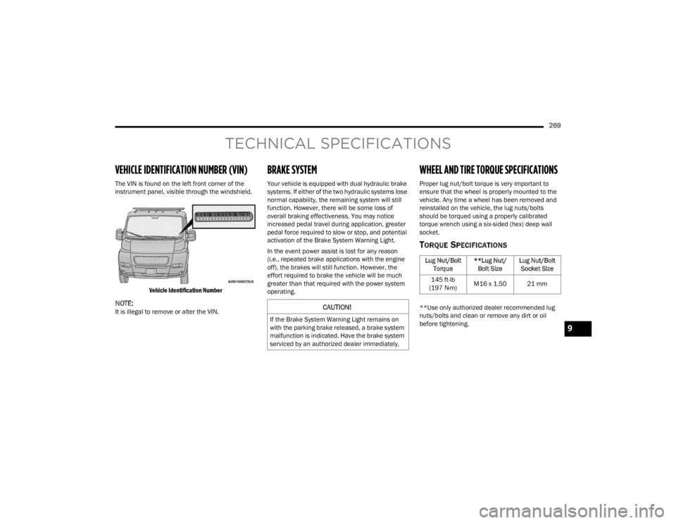
VEHICLE IDENTIFICATION NUMBER (VIN)
The VIN is found on the left front corner of the
instrument panel, visible through the windshield.
Vehicle Identification Number
NOTE:It is illegal to remove or alter the VIN.
BRAKE SYSTEM
Your vehicle is equipped with dual hydraulic brake
systems. If either of the two hydraulic systems lose
normal capability, the remaining system will still
function. However, there will be some loss of
overall braking effectiveness. You may notice
increased pedal travel during application, greater
pedal force required to slow or stop, and potential
activation of the Brake System Warning Light.
In the event power assist is lost for any reason
(i.e., repeated brake applications with the engine
off), the brakes will still function. However, the
effort required to brake the vehicle will be much
greater than that required with the power system
operating.
WHEEL AND TIRE TORQUE SPECIFICATIONS
Proper lug nut/bolt torque is very important to
ensure that the wheel is properly mounted to the
vehicle. Any time a wheel has been removed and
reinstalled on the vehicle, the lug nuts/bolts
should be torqued using a properly calibrated
torque wrench using a six-sided (hex) deep wall
socket.
TORQUE SPECIFICATIONS
**Use only authorized dealer recommended lug
nuts/bolts and clean or remove any dirt or oil
before tightening.CAUTION!
If the Brake System Warning Light remains on
with the parking brake released, a brake system
malfunction is indicated. Have the brake system
serviced by an authorized dealer immediately.
Lug Nut/Bolt Torque **Lug Nut/
Bolt Size Lug Nut/Bolt
Socket Size
145 ft-lb
(197 N·m) M16 x 1.50 21 mm
9
23_VF_OM_EN_USC_t.book Page 269
Page 286 of 296

284 Brake/Transmission Interlock
......................... 81Bulb Replacement......................................... 244Bulbs, Light.......................................... 191, 244
C
Camera, Rear...................................... 119, 120Capacities, Fluid............................................ 273Caps, Filler Fuel........................................................... 122Oil (Engine)................................................ 225Radiator (Coolant Pressure)...................... 234Car Washes................................................... 266Carbon Monoxide Warning............................ 192Cargo Area Cover............................................. 51Cargo Compartment........................................ 51Cargo Light...................................................... 36Cellular Phone............................................... 151Certification Label......................................... 123Change Engine Oil — If Equipped
S
.............. 57Change Oil Indicator........................................ 57Changing A Flat Tire....................................... 196Chart, Tire Sizing............................................ 250Check Engine Light (Malfunction
Indicator Light)................................................ 74Checking Your Vehicle For Safety.................. 189Checks, Safety............................................... 189Child Restraint............................................... 185
Child RestraintsBooster Seats........................................... 187Child Seat Installation.............................. 189Infant And Child Restraints....................... 186Older Children And Child Restraints......... 187Clean Air Gasoline......................................... 271CleaningWheels..................................................... 262Climate Control................................................ 40Manual........................................................ 40Rear............................................................. 43Cold Weather Operation.................................. 76Compact Spare Tire...................................... 260Contract, Service.......................................... 277Cooling Pressure Cap (Radiator Cap)............ 234Cooling System............................................. 233Adding Coolant (Antifreeze)...................... 233Coolant Level................................... 233, 234Cooling Capacity....................................... 273Disposal Of Used Coolant......................... 234Drain, Flush, And Refill............................. 233Inspection................................................. 234Points To Remember................................ 234Pressure Cap............................................ 234Radiator Cap............................................ 234Selection Of Coolant (Antifreeze)..... 233, 273Corrosion Protection..................................... 265Cruise Control (Speed Control)................. 87, 88
Cruise Light......................................................72Customer Assistance.................................... 275Customer Programmable Features............... 134Cybersecurity................................................ 133
D
Dealer Service............................................... 227Defroster, Windshield................................... 190Diagnostic System, Onboard............................74Dimmer Control Switch....................................37Dimmer SwitchHeadlight.....................................................34DipsticksAutomatic Transmission........................... 236Oil (Engine)............................................... 226Disable Vehicle Towing................................. 219DisposalAntifreeze (Engine Coolant)...................... 234Door Ajar..........................................................66Door Ajar Light.................................................66Door Locks.......................................................21Automatic....................................................23Doors...............................................................21Driver’s Seat Back Tilt......................................23DrivingThrough Flowing, Rising, Or Shallow Standing Water
.................................................... 131Drowsy Driver Detection................................ 157
23_VF_OM_EN_USC_t.book Page 284