warning light RAM PROMASTER 2023 Owners Manual
[x] Cancel search | Manufacturer: RAM, Model Year: 2023, Model line: PROMASTER, Model: RAM PROMASTER 2023Pages: 296, PDF Size: 12.31 MB
Page 5 of 296
3
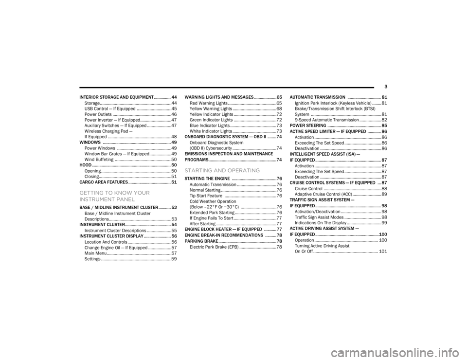
INTERIOR STORAGE AND EQUIPMENT ............... 44 Storage..............................................................44
USB Control — If Equipped ..............................45
Power Outlets ...................................................46
Power Inverter — If Equipped...........................47
Auxiliary Switches — If Equipped .....................47
Wireless Charging Pad —
If Equipped .......................................................48
WINDOWS ............................................................. 49
Power Windows ...............................................49
Window Bar Grates — If Equipped...................49
Wind Buffeting .................................................50
HOOD....................................................................... 50
Opening .............................................................50
Closing...............................................................51
CARGO AREA FEATURES ...................................... 51
GETTING TO KNOW YOUR
INSTRUMENT PANEL
BASE / MIDLINE INSTRUMENT CLUSTER........... 52
Base / Midline Instrument Cluster
Descriptions ......................................................53
INSTRUMENT CLUSTER......................................... 54
Instrument Cluster Descriptions .....................55
INSTRUMENT CLUSTER DISPLAY ........................ 56
Location And Controls ......................................56
Change Engine Oil — If Equipped ....................57
Main Menu........................................................57
Settings .............................................................59 WARNING LIGHTS AND MESSAGES ....................65
Red Warning Lights ..........................................65
Yellow Warning Lights ......................................68
Yellow Indicator Lights .....................................72
Green Indicator Lights .....................................72
Blue Indicator Lights ........................................73
White Indicator Lights ......................................73
ONBOARD DIAGNOSTIC SYSTEM — OBD II ........ 74
Onboard Diagnostic System
(OBD II) Cybersecurity ......................................74
EMISSIONS INSPECTION AND MAINTENANCE
PROGRAMS.............................................................74
STARTING AND OPERATING
STARTING THE ENGINE ........................................76
Automatic Transmission ..................................76
Normal Starting ................................................76
Tip Start Feature .............................................76
Cold Weather Operation
(Below –22°F Or −30°C) ...............................76
Extended Park Starting ....................................76
If Engine Fails To Start .....................................77
After Starting ....................................................77
ENGINE BLOCK HEATER — IF EQUIPPED ...........77
ENGINE BREAK-IN RECOMMENDATIONS ..........78
PARKING BRAKE ....................................................78
Electric Park Brake (EPB) ................................78 AUTOMATIC TRANSMISSION .............................. 81
Ignition Park Interlock (Keyless Vehicle) ........ 81
Brake/Transmission Shift Interlock (BTSI)
System ............................................................. 81
9-Speed Automatic Transmission ................... 82
POWER STEERING ................................................ 85
ACTIVE SPEED LIMITER — IF EQUIPPED ............ 86
Activation .......................................................... 86
Exceeding The Set Speed ................................ 86
Deactivation ..................................................... 86
INTELLIGENT SPEED ASSIST (ISA) —
IF EQUIPPED ........................................................... 87
Activation .......................................................... 87
Exceeding The Set Speed ................................ 87
Deactivation ..................................................... 87
CRUISE CONTROL SYSTEMS — IF EQUIPPED ... 87
Cruise Control .................................................. 88
Adaptive Cruise Control (ACC) ......................... 89
TRAFFIC SIGN ASSIST SYSTEM —
IF EQUIPPED ........................................................... 98
Activation/Deactivation ................................... 98
Traffic Sign Assist Modes ................................ 98
Indications On The Display .............................. 99
ACTIVE DRIVING ASSIST SYSTEM —
IF EQUIPPED ......................................................... 100
Operation ....................................................... 100Turning Active Driving Assist
On Or Off ........................................................ 101
23_VF_OM_EN_USC_t.book Page 3
Page 11 of 296
9
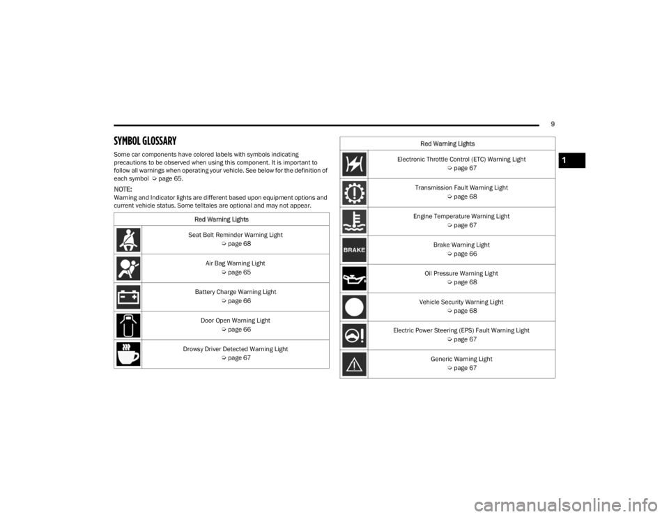
SYMBOL GLOSSARY
Some car components have colored labels with symbols indicating
precautions to be observed when using this component. It is important to
follow all warnings when operating your vehicle. See below for the definition of
each symbol Úpage 65.
NOTE:Warning and Indicator lights are different based upon equipment options and
current vehicle status. Some telltales are optional and may not appear.
Red Warning Lights
Seat Belt Reminder Warning Light Úpage 68
Air Bag Warning Light Úpage 65
Battery Charge Warning Light Úpage 66
Door Open Warning Light Úpage 66
Drowsy Driver Detected Warning Light Úpage 67
Electronic Throttle Control (ETC) Warning Light
Úpage 67
Transmission Fault Warning Light Úpage 68
Engine Temperature Warning Light Úpage 67
Brake Warning Light Úpage 66
Oil Pressure Warning Light Úpage 68
Vehicle Security Warning Light Úpage 68
Electric Power Steering (EPS) Fault Warning Light Úpage 67
Generic Warning Light Úpage 67
Red Warning Lights1
23_VF_OM_EN_USC_t.book Page 9
Page 12 of 296
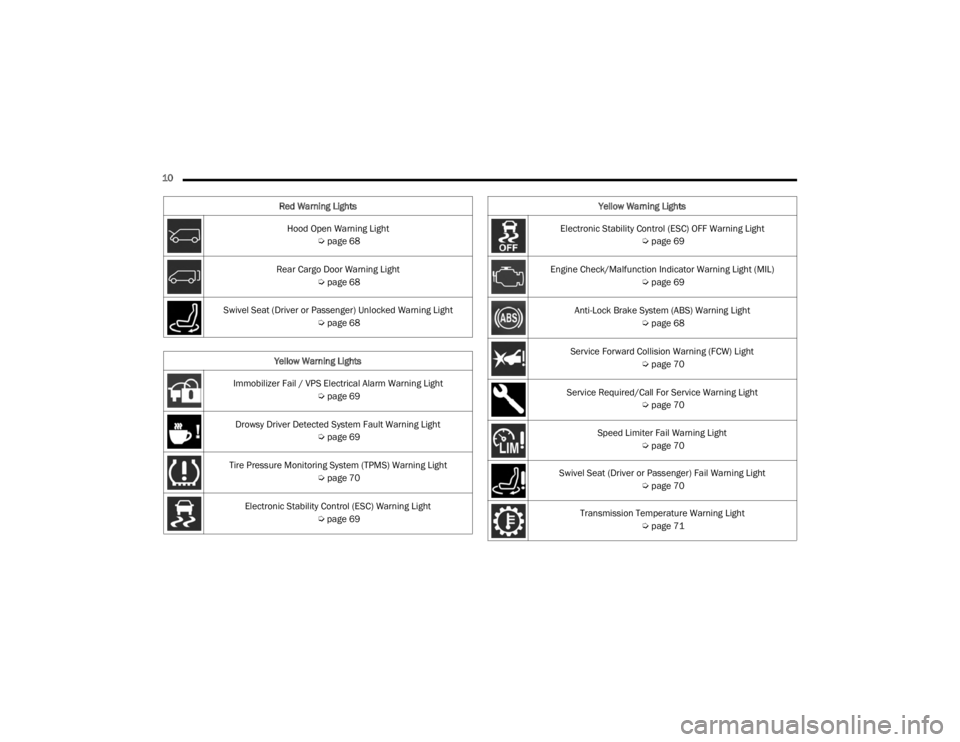
10 Hood Open Warning Light Úpage 68
Rear Cargo Door Warning Light Úpage 68
Swivel Seat (Driver or Passenger) Unlocked Warning Light Úpage 68
Yellow Warning Lights
Immobilizer Fail / VPS Electrical Alarm Warning Light Úpage 69
Drowsy Driver Detected System Fault Warning Light Úpage 69
Tire Pressure Monitoring System (TPMS) Warning Light Úpage 70
Electronic Stability Control (ESC) Warning Light Úpage 69
Red Warning Lights
Electronic Stability Control (ESC) OFF Warning Light
Úpage 69
Engine Check/Malfunction Indicator Warning Light (MIL) Úpage 69
Anti-Lock Brake System (ABS) Warning Light Úpage 68
Service Forward Collision Warning (FCW) Light Úpage 70
Service Required/Call For Service Warning Light Úpage 70
Speed Limiter Fail Warning Light Úpage 70
Swivel Seat (Driver or Passenger) Fail Warning Light Úpage 70
Transmission Temperature Warning Light Úpage 71
Yellow Warning Lights
23_VF_OM_EN_USC_t.book Page 10
Page 13 of 296
11
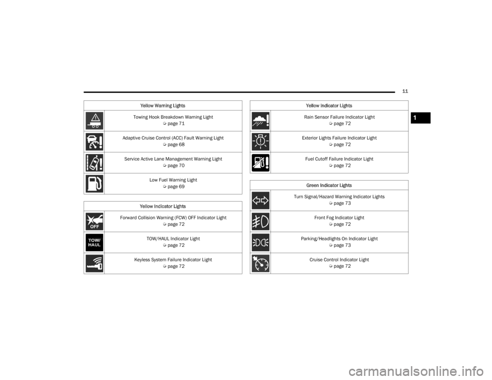
Towing Hook Breakdown Warning Light Úpage 71
Adaptive Cruise Control (ACC) Fault Warning Light Úpage 68
Service Active Lane Management Warning Light Úpage 70
Low Fuel Warning Light Úpage 69
Yellow Indicator Lights
Forward Collision Warning (FCW) OFF Indicator Light Úpage 72
TOW/HAUL Indicator Light Úpage 72
Keyless System Failure Indicator Light Úpage 72
Yellow Warning Lights
Rain Sensor Failure Indicator Light
Úpage 72
Exterior Lights Failure Indicator Light Úpage 72
Fuel Cutoff Failure Indicator Light Úpage 72
Green Indicator Lights
Turn Signal/Hazard Warning Indicator Lights Úpage 73
Front Fog Indicator Light Úpage 72
Parking/Headlights On Indicator Light Úpage 73
Cruise Control Indicator Light Úpage 72
Yellow Indicator Lights1
23_VF_OM_EN_USC_t.book Page 11
Page 14 of 296
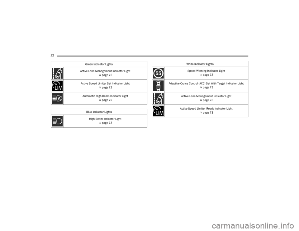
12 Active Lane Management Indicator Light Úpage 72
Active Speed Limiter Set Indicator Light Úpage 72
Automatic High Beam Indicator Light Úpage 72
Blue Indicator Lights High Beam Indicator Light Úpage 73
Green Indicator Lights
White Indicator Lights
Speed Warning Indicator Light Úpage 73
Adaptive Cruise Control (ACC) Set With Target Indicator Light Úpage 73
Active Lane Management Indicator Light Úpage 73
Active Speed Limiter Ready Indicator Light Úpage 73
23_VF_OM_EN_USC_t.book Page 12
Page 20 of 296
18GETTING TO KNOW YOUR VEHICLE
REMOTE START — IF EQUIPPED
This system uses the key fob to start the
engine conveniently from outside the
vehicle while still maintaining security.
The system has a range of approximately
300 ft (91 m).
Remote Start is used to defrost windows in cold
weather, and to reach a comfortable climate in all
ambient conditions before the driver enters the
vehicle.
NOTE:Obstructions between the vehicle and the key fob
may reduce this range Ú page 280.
HOW TO USE REMOTE START
Push and release the Remote Start button on the
key fob twice within five seconds. The vehicle
doors will lock, the parking lights will flash, and the
horn will chirp twice (if programmed). Then, the
engine will start, and the vehicle will remain in the
Remote Start mode for a 15 minute cycle.
Pushing the Remote Start button a third time shuts
the engine off.
NOTE:
With Remote Start, the engine will only run for
15 minutes.
Remote Start can only be used twice.
If an engine fault is present or fuel level is low,
the vehicle will not start.
The parking lights will turn on and remain on
during Remote Start mode.
For security, power window is disabled when the
vehicle is in the Remote Start mode.
The ignition must be placed in the ON/RUN posi -
tion before the Remote Start sequence can be
repeated for a third cycle.
All of the following conditions must be met before
the engine will Remote Start:
Gear selector in PARK
Doors closed
Hood closed
Rear cargo doors closed
Hazard switch off
Brake switch inactive (brake pedal not pressed)
Battery at an acceptable charge level
Panic button not pushed
Fuel meets minimum requirement
System not disabled from previous Remote
Start event
Vehicle Security system not active
Malfunction Indicator Light (MIL) is not illuminated
Ignition in OFF position
WARNING!
Do not start or run an engine in a closed garage
or confined area. Exhaust gas contains carbon
monoxide (CO) which is odorless and colorless.
Carbon monoxide is poisonous and can cause
serious injury or death when inhaled.
Keep key fobs away from children. Operation
of the Remote Start system, windows, door
locks or other controls could cause serious
injury or death.
23_VF_OM_EN_USC_t.book Page 18
Page 23 of 296
GETTING TO KNOW YOUR VEHICLE21
(Continued)
SECURITY SYSTEM MANUAL OVERRIDE
The Vehicle Security system will not arm if you lock
the doors using the manual door lock.
DOORS
POWER DOOR LOCKS
The power lock/unlock button has an LED that
indicates whether the doors are locked or
unlocked.
Push the lock button on the instrument panel.
The indicator light will illuminate to show the doors
are locked.
Push the lock button on the instrument panel a
second time to unlock the doors.
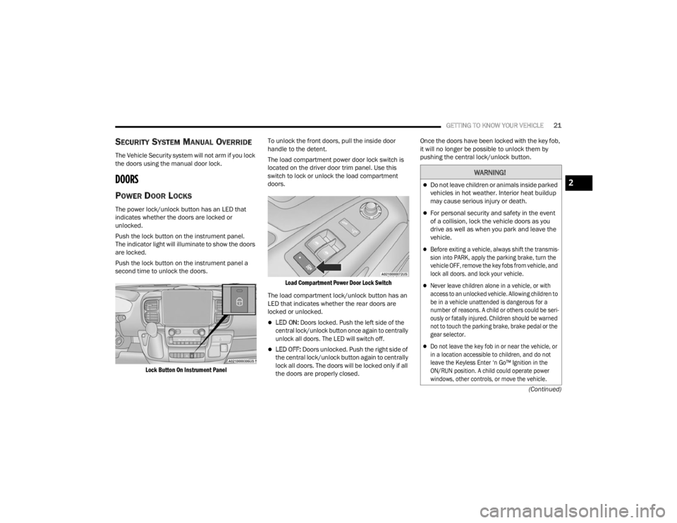
Lock Button On Instrument Panel
To unlock the front doors, pull the inside door
handle to the detent.
The load compartment power door lock switch is
located on the driver door trim panel. Use this
switch to lock or unlock the load compartment
doors.
Load Compartment Power Door Lock Switch
The load compartment lock/unlock button has an
LED that indicates whether the rear doors are
locked or unlocked.
LED ON:
Doors locked. Push the left side of the
central lock/unlock button once again to centrally
unlock all doors. The LED will switch off.
LED OFF: Doors unlocked. Push the right side of
the central lock/unlock button again to centrally
lock all doors. The doors will be locked only if all
the doors are properly closed. Once the doors have been locked with the key fob,
it will no longer be possible to unlock them by
pushing the central lock/unlock button.
WARNING!
Do not leave children or animals inside parked
vehicles in hot weather. Interior heat buildup
may cause serious injury or death.
For personal security and safety in the event
of a collision, lock the vehicle doors as you
drive as well as when you park and leave the
vehicle.
Before exiting a vehicle, always shift the transmis
-
sion into PARK, apply the parking brake, turn the
vehicle OFF, remove the key fobs from vehicle, and
lock all doors. and lock your vehicle.
Never leave children alone in a vehicle, or with
access to an unlocked vehicle. Allowing children to
be in a vehicle unattended is dangerous for a
number of reasons. A child or others could be seri -
ously or fatally injured. Children should be warned
not to touch the parking brake, brake pedal or the
gear selector.
Do not leave the key fob in or near the vehicle, or
in a location accessible to children, and do not
leave the Keyless Enter ‘n Go™ Ignition in the
ON/RUN position. A child could operate power
windows, other controls, or move the vehicle.
2
23_VF_OM_EN_USC_t.book Page 21
Page 27 of 296
GETTING TO KNOW YOUR VEHICLE25
(Continued)
Recliner Adjustment
Without Swivel Seat
The recliner knob is on the rear outboard side of the
seat. To recline the seatback, lean back and rotate
the knob rearward to position the seatback as desired.
To return the seatback to its normal upright position,
lean forward and rotate the knob forward until the
seatback is in the upright position.
With Swivel Seat
The recliner lever is located at the lower front outboard
side of the seat. To recline the seatback, lean forward
slightly, pull the lever outward, lean back to the desired
position and release the lever. To return the seatback
to its normal upright position, lean forward and pull the
lever outward. Release the lever once the seatback is
in the upright position.
Lumbar Support — If Equipped
This feature allows you to increase or decrease the
amount of lumbar support. The lumbar control
knob is located on the rear upper outboard side of
the driver's seatback. Rotate the control forward to
increase and rearward to decrease the desired
amount of lumbar support.
Suspension Seat — If Equipped
The seat is equipped with a mechanical spring
system and hydraulic shock absorber to ensure
maximum comfort and safety. The system of
springs also effectively absorbs impact from
uneven road surfaces. Damper Weight Adjustment
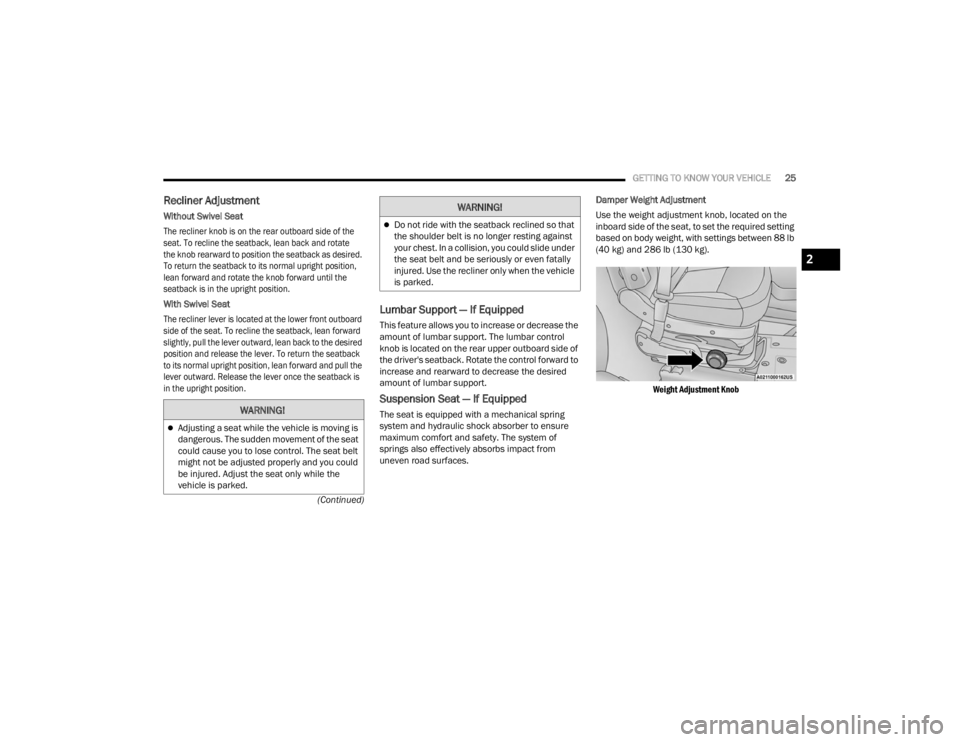
Use the weight adjustment knob, located on the
inboard side of the seat, to set the required setting
based on body weight, with settings between 88 lb
(40 kg) and 286 lb (130 kg).
Weight Adjustment Knob
WARNING!
Adjusting a seat while the vehicle is moving is
dangerous. The sudden movement of the seat
could cause you to lose control. The seat belt
might not be adjusted properly and you could
be injured. Adjust the seat only while the
vehicle is parked.
Do not ride with the seatback reclined so that
the shoulder belt is no longer resting against
your chest. In a collision, you could slide under
the seat belt and be seriously or even fatally
injured. Use the recliner only when the vehicle
is parked.
WARNING!
2
23_VF_OM_EN_USC_t.book Page 25
Page 28 of 296
26GETTING TO KNOW YOUR VEHICLE
Swivel Seat — If Equipped
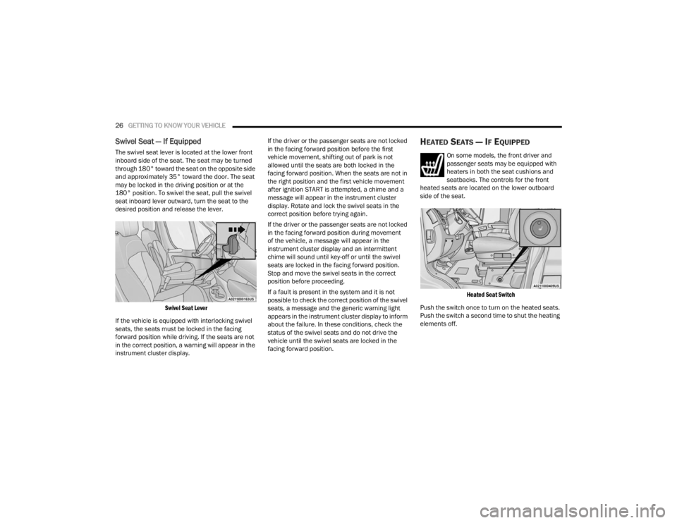
The swivel seat lever is located at the lower front
inboard side of the seat. The seat may be turned
through 180° toward the seat on the opposite side
and approximately 35° toward the door. The seat
may be locked in the driving position or at the
180° position. To swivel the seat, pull the swivel
seat inboard lever outward, turn the seat to the
desired position and release the lever.
Swivel Seat Lever
If the vehicle is equipped with interlocking swivel
seats, the seats must be locked in the facing
forward position while driving. If the seats are not
in the correct position, a warning will appear in the
instrument cluster display. If the driver or the passenger seats are not locked
in the facing forward position before the first
vehicle movement, shifting out of park is not
allowed until the seats are both locked in the
facing forward position. When the seats are not in
the right position and the first vehicle movement
after ignition START is attempted, a chime and a
message will appear in the instrument cluster
display. Rotate and lock the swivel seats in the
correct position before trying again.
If the driver or the passenger seats are not locked
in the facing forward position during movement
of the vehicle, a message will appear in the
instrument cluster display and an intermittent
chime will sound until key-off or until the swivel
seats are locked in the facing forward position.
Stop and move the swivel seats in the correct
position before proceeding.
If a fault is present in the system and it is not
possible to check the correct position of the swivel
seats, a message and the generic warning light
appears in the instrument cluster display to inform
about the failure. In these conditions, check the
status of the swivel seats and do not drive the
vehicle until the swivel seats are locked in the
facing forward position.
HEATED SEATS — IF EQUIPPED
On some models, the front driver and
passenger seats may be equipped with
heaters in both the seat cushions and
seatbacks. The controls for the front
heated seats are located on the lower outboard
side of the seat.
Heated Seat Switch
Push the switch once to turn on the heated seats.
Push the switch a second time to shut the heating
elements off.
23_VF_OM_EN_USC_t.book Page 26
Page 33 of 296
GETTING TO KNOW YOUR VEHICLE31
NOTE:The Digital Rearview Mirror is not as effective when
driving in the following conditions:
Nighttime in low light applications
Bad weather conditions (e.g. extreme haze,
snow/slush)
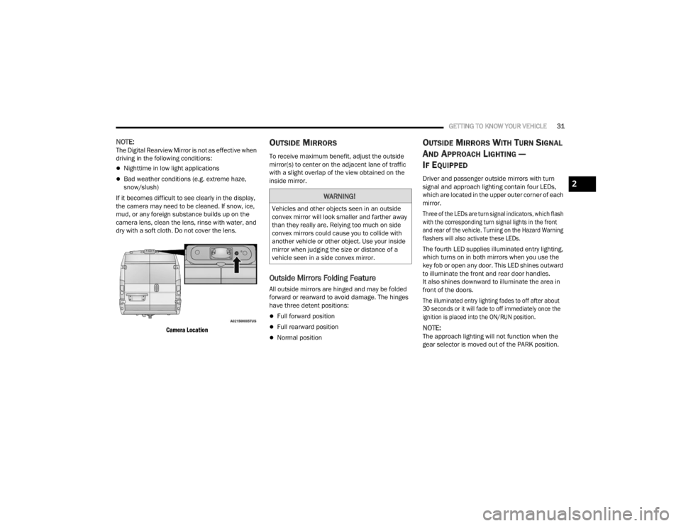
If it becomes difficult to see clearly in the display,
the camera may need to be cleaned. If snow, ice,
mud, or any foreign substance builds up on the
camera lens, clean the lens, rinse with water, and
dry with a soft cloth. Do not cover the lens.
Camera Location
OUTSIDE MIRRORS
To receive maximum benefit, adjust the outside
mirror(s) to center on the adjacent lane of traffic
with a slight overlap of the view obtained on the
inside mirror.
Outside Mirrors Folding Feature
All outside mirrors are hinged and may be folded
forward or rearward to avoid damage. The hinges
have three detent positions:
Full forward position
Full rearward position
Normal position
OUTSIDE MIRRORS WITH TURN SIGNAL
A
ND APPROACH LIGHTING —
I
F EQUIPPED
Driver and passenger outside mirrors with turn
signal and approach lighting contain four LEDs,
which are located in the upper outer corner of each
mirror.
Three of the LEDs are turn signal indicators, which flash
with the corresponding turn signal lights in the front
and rear of the vehicle. Turning on the Hazard Warning
flashers will also activate these LEDs.
The fourth LED supplies illuminated entry lighting,
which turns on in both mirrors when you use the
key fob or open any door. This LED shines outward
to illuminate the front and rear door handles.
It also shines downward to illuminate the area in
front of the doors.
The illuminated entry lighting fades to off after about
30 seconds or it will fade to off immediately once the
ignition is placed into the ON/RUN position.
NOTE:The approach lighting will not function when the
gear selector is moved out of the PARK position.
WARNING!
Vehicles and other objects seen in an outside
convex mirror will look smaller and farther away
than they really are. Relying too much on side
convex mirrors could cause you to collide with
another vehicle or other object. Use your inside
mirror when judging the size or distance of a
vehicle seen in a side convex mirror.
2
23_VF_OM_EN_USC_t.book Page 31