engine coolant RAM PROMASTER 2023 Owners Manual
[x] Cancel search | Manufacturer: RAM, Model Year: 2023, Model line: PROMASTER, Model: RAM PROMASTER 2023Pages: 296, PDF Size: 12.31 MB
Page 45 of 296

GETTING TO KNOW YOUR VEHICLE43
Climate Control OFF Button
Press and release this button to turn the
Climate Control ON/OFF.
ADDITIONAL REAR CLIMATE CONTROL â
I
F EQUIPPED
These switches, mounted on the instrument panel
to the left of the steering column, activate the
additional rear heating/air conditioning system.
NOTE:These switches must be enabled for operation by
the Upfitter.
Additional Rear Climate Controls Switches
Rear Blower Control
Push this button to turn on the rear climate
controls. An indicator light will turn on when
the rear climate control is on.
OPERATING TIPS
Refer to the chart at the end of this section for
suggested control settings for various weather
conditions.
Summer Operation
The engine cooling system must be protected
with a high-quality antifreeze coolant to provide
proper corrosion protection and to protect against
engine overheating. OAT coolant (conforming to
MS.90032) is recommended.
Winter Operation
To ensure the best possible heater and defroster
performance, make sure the engine cooling
system is functioning properly and the proper
amount, type, and concentration of coolant is
used. Use of the Air Recirculation mode during
Winter months is not recommended, because it
may cause window fogging.
Vacation Storage
For information on maintaining the Climate Control
system when the vehicle is being stored for an
extended period of time, see à page 265.
Window Fogging
Vehicle windows tend to fog on the inside in mild, rainy,
and/or humid weather. To clear the windows, select
Defrost or Mix mode and increase the front blower
speed. Do not use the Recirculation mode without A/C
for long periods, as fogging may occur.
Outside Air Intake
Make sure the air intake, located directly in front of
the windshield, is free of obstructions, such as
leaves. Leaves collected in the air intake may
reduce airflow, and if they enter the air distribution
box, they could plug the water drains. In Winter
months, make sure the air intake is clear of ice,
slush, and snow.
Cabin Air Filter
The Climate Control system filters out dust and
pollen from the air. Contact an authorized dealer to
service your cabin air filter, and to have it replaced
when needed.
2
23_VF_OM_EN_USC_t.book Page 43
Page 55 of 296
GETTING TO KNOW YOUR INSTRUMENT PANEL53
Use this QR code to access your
digital experience.
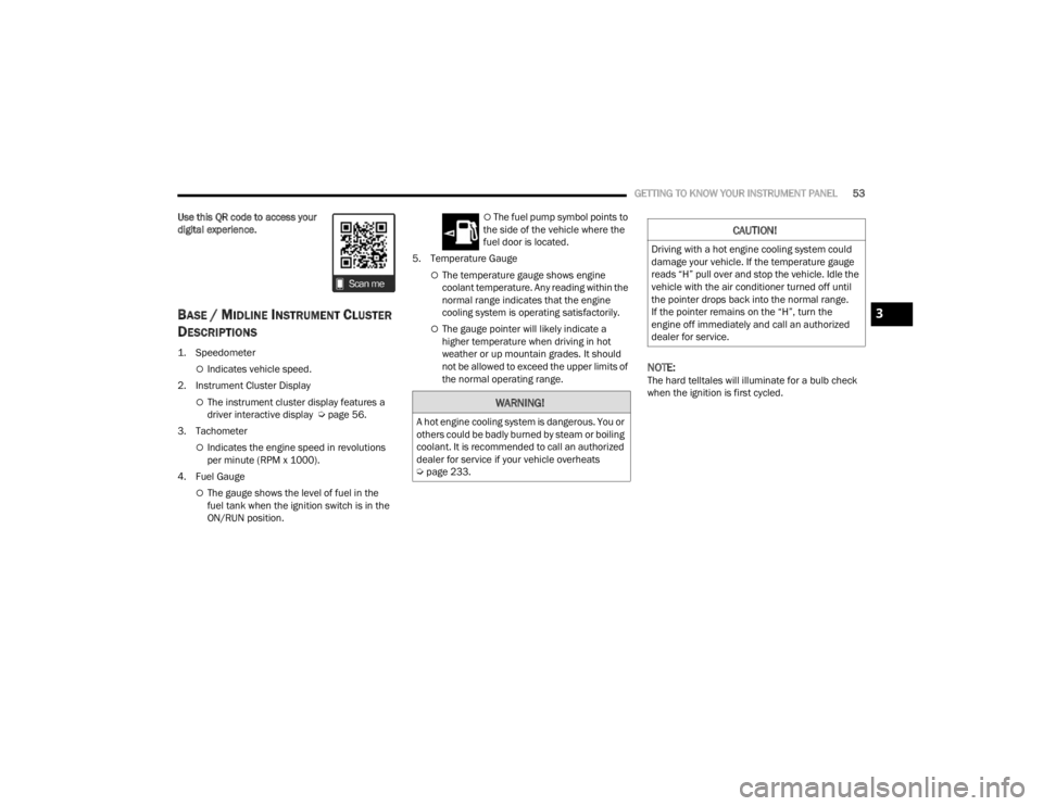
BASE / MIDLINE INSTRUMENT CLUSTER
D
ESCRIPTIONS
1. Speedometer
ï¡Indicates vehicle speed.
2. Instrument Cluster Display
ï¡The instrument cluster display features a
driver interactive display à page 56.
3. Tachometer
ï¡Indicates the engine speed in revolutions
per minute (RPM x 1000).
4. Fuel Gauge
ï¡The gauge shows the level of fuel in the
fuel tank when the ignition switch is in the
ON/RUN position.
ï¡ The fuel pump symbol points to
the side of the vehicle where the
fuel door is located.
5. Temperature Gauge
ï¡The temperature gauge shows engine
coolant temperature. Any reading within the
normal range indicates that the engine
cooling system is operating satisfactorily.
ï¡The gauge pointer will likely indicate a
higher temperature when driving in hot
weather or up mountain grades. It should
not be allowed to exceed the upper limits of
the normal operating range.
NOTE:The hard telltales will illuminate for a bulb check
when the ignition is first cycled.
WARNING!
A hot engine cooling system is dangerous. You or
others could be badly burned by steam or boiling
coolant. It is recommended to call an authorized
dealer for service if your vehicle overheats
à page 233.
CAUTION!
Driving with a hot engine cooling system could
damage your vehicle. If the temperature gauge
reads âHâ pull over and stop the vehicle. Idle the
vehicle with the air conditioner turned off until
the pointer drops back into the normal range.
If the pointer remains on the âHâ, turn the
engine off immediately and call an authorized
dealer for service.
3
23_VF_OM_EN_USC_t.book Page 53
Page 57 of 296
GETTING TO KNOW YOUR INSTRUMENT PANEL55
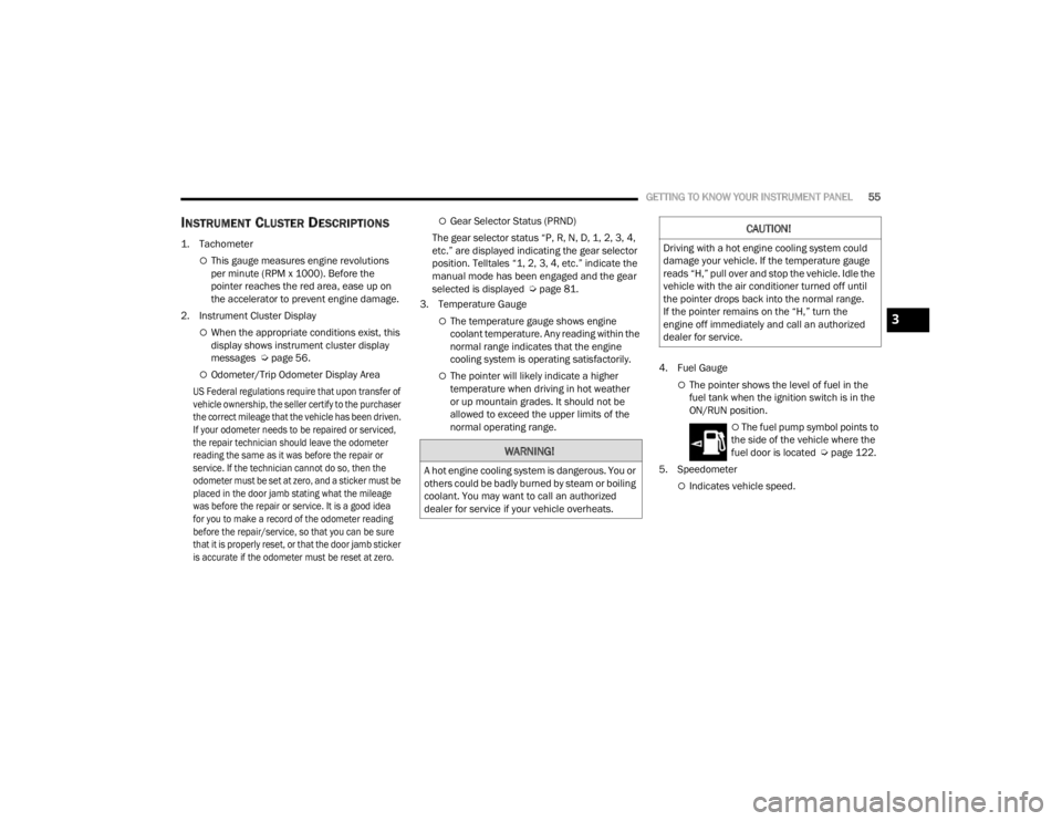
INSTRUMENT CLUSTER DESCRIPTIONS
1. Tachometer
ï¡This gauge measures engine revolutions
per minute (RPM x 1000). Before the
pointer reaches the red area, ease up on
the accelerator to prevent engine damage.
2. Instrument Cluster Display
ï¡When the appropriate conditions exist, this
display shows instrument cluster display
messages à page 56.
ï¡Odometer/Trip Odometer Display Area
US Federal regulations require that upon transfer of
vehicle ownership, the seller certify to the purchaser
the correct mileage that the vehicle has been driven.
If your odometer needs to be repaired or serviced,
the repair technician should leave the odometer
reading the same as it was before the repair or
service. If the technician cannot do so, then the
odometer must be set at zero, and a sticker must be
placed in the door jamb stating what the mileage
was before the repair or service. It is a good idea
for you to make a record of the odometer reading
before the repair/service, so that you can be sure
that it is properly reset, or that the door jamb sticker
is accurate if the odometer must be reset at zero.
ï¡Gear Selector Status (PRND)
The gear selector status âP, R, N, D, 1, 2, 3, 4,
etc.â are displayed indicating the gear selector
position. Telltales â1, 2, 3, 4, etc.â indicate the
manual mode has been engaged and the gear
selected is displayed à page 81.
3. Temperature Gauge
ï¡The temperature gauge shows engine
coolant temperature. Any reading within the
normal range indicates that the engine
cooling system is operating satisfactorily.
ï¡The pointer will likely indicate a higher
temperature when driving in hot weather
or up mountain grades. It should not be
allowed to exceed the upper limits of the
normal operating range. 4. Fuel Gaugeï¡The pointer shows the level of fuel in the
fuel tank when the ignition switch is in the
ON/RUN position.
ï¡ The fuel pump symbol points to
the side of the vehicle where the
fuel door is located à page 122.
5. Speedometer
ï¡Indicates vehicle speed.
WARNING!
A hot engine cooling system is dangerous. You or
others could be badly burned by steam or boiling
coolant. You may want to call an authorized
dealer for service if your vehicle overheats.
CAUTION!
Driving with a hot engine cooling system could
damage your vehicle. If the temperature gauge
reads âH,â pull over and stop the vehicle. Idle the
vehicle with the air conditioner turned off until
the pointer drops back into the normal range.
If the pointer remains on the âH,â turn the
engine off immediately and call an authorized
dealer for service.
3
23_VF_OM_EN_USC_t.book Page 55
Page 69 of 296

GETTING TO KNOW YOUR INSTRUMENT PANEL67
Drowsy Driver Detected Warning Light â
If Equipped
Drowsy driver detection helps to avoid
crashes caused by fatigue by advising
drivers to take a break in time. Once a
Drowsy Driver is detected, A pop-up will
display continuously until the driver presses the
OK button to clear.
Once the pop-up message is cleared, it is stored
until the condition is no longer true.
Electric Power Steering (EPS) Fault
Warning Light
This warning light will turn on when
there's a fault with the EPS system
à page 85.
Electronic Throttle Control (ETC) Warning
Light
This warning light will illuminate to inform of
a problem with the ETC system. If a problem
is detected while the vehicle is running, the
light will either stay on or flash depending on
the nature of the problem. Cycle the ignition when
the vehicle is safely and completely stopped and the
transmission is placed in the PARK (P) position.
The light should turn off. If the light remains on with the
vehicle running, your vehicle will usually be drivable;
however, see an authorized dealer for service as soon
as possible.
If the light continues to flash when the vehicle is
running, immediate service is required and you may
experience reduced performance, an elevated/
rough idle, or engine stall and your vehicle may
require towing. The light will come on when the
ignition is placed in the ON/RUN or MAR/ON/RUN
position and remain on briefly as a bulb check. If the
light does not come on during starting, have the
system checked by an authorized dealer.
Engine Temperature Warning Light
This light warns of an overheated
engine condition. If the engine coolant
temperature is too high, this indicator will
illuminate and a single chime will sound.
If the light turns on while driving, safely pull over and
stop the vehicle. If the Air Conditioning (A/C) system is
on, turn it off. Also, shift the transmission into NEUTRAL
and idle the vehicle. If the temperature reading does
not return to normal, turn the engine off immediately
and call for service
Ã
page 216.
Generic Warning Light
The Generic Warning Light will illuminate
to signal the failure of one or more safety
warning lights with a corresponding
message. The safety systems that may
cause the Generic Warning Light to illuminate
include but are not limited too: Seat belt Reminder,
Electric Park Brake, Brakes, Air Bag, and Swivel
Seat failure.
The telltale will remain on in case of swivel seat
failure and will blink in case of Air Bag Warning
Light Failure. Contact an authorized dealer
immediately for service.
WARNING!
Continued operation with reduced assist could
pose a safety risk to yourself and others. Service
should be obtained as soon as possible.
3
23_VF_OM_EN_USC_t.book Page 67
Page 193 of 296
SAFETY191
(Continued)
PERIODIC SAFETY CHECKS YOU SHOULD
M
AKE OUTSIDE THE VEHICLE
Tires
Examine tires for excessive tread wear and uneven
wear patterns. Check for stones, nails, glass, or
other objects lodged in the tread or sidewall.
Inspect the tread for cuts and cracks. Inspect
sidewalls for cuts, cracks, and bulges. Check the
lug nut/bolt torque for tightness. Check the tires
(including spare) for proper cold inflation pressure.
Lights
Have someone observe the operation of brake
lights and exterior lights while you work the
controls. Check turn signal and high beam
indicator lights on the instrument panel.
Door Latches
Check for proper closing, latching, and locking.
Fluid Leaks
Check area under the vehicle after overnight
parking for fuel, coolant, oil, or other fluid leaks.
Also, if gasoline fumes are detected or if fuel or
brake fluid leaks are suspected, the cause should
be located and corrected immediately.
ï¬ ALWAYS REMOVE THE EXISTING
FLOOR MAT FROM THE VEHICLE
before installing any other floor mat.
NEVER install or stack an additional
floor mat on top of an existing floor mat.
ï¬ONLY install floor mats designed to fit your vehicle.
NEVER install a floor mat that cannot be properly
attached and secured to your vehicle. If a floor mat
needs to be replaced, only use a FCA approved
floor mat for the specific make, model, and year of
your vehicle.
ï¬ONLY use the driverâs side floor mat on the driverâs
side floor area. To check for interference, with the
vehicle properly parked with the engine off, fully
depress the accelerator, the brake, and the clutch
pedal (if present) to check for interference. If your
floor mat interferes with the operation of any
pedal, or is not secure to the floor, remove the
floor mat from the vehicle and place the floor mat
in your trunk.
ï¬ONLY use the passengerâs side floor mat on
the passengerâs side floor area.
WARNING!
ï¬ALWAYS make sure objects cannot fall or slide into
the driverâs side floor area when the vehicle is
moving. Objects can become trapped under accel -
erator, brake, or clutch pedals and could cause a
loss of vehicle control.
ï¬NEVER place any objects under the floor mat
(e.g., towels, keys, etc.). These objects could
change the position of the floor mat and may
cause interference with the accelerator,
brake, or clutch pedals.
ï¬If the vehicle carpet has been removed and
re-installed, always properly attach carpet to
the floor and check the floor mat fasteners are
secure to the vehicle carpet. Fully depress
each pedal to check for interference with the
accelerator, brake, or clutch pedals then
re-install the floor mats.
ï¬It is recommended to only use mild soap and
water to clean your floor mats. After cleaning,
always check your floor mat has been properly
installed and is secured to your vehicle using
the floor mat fasteners by lightly pulling mat.
WARNING!
6
23_VF_OM_EN_USC_t.book Page 191
Page 219 of 296

IN CASE OF EMERGENCY217
GEAR SELECTOR OVERRIDE
If a malfunction occurs and the gear selector
cannot be moved out of the PARK (P) position, you
can use the following procedure to temporarily
move the gear selector:
1. Turn the engine OFF.
2. Firmly apply the parking brake.
3. Using a small screwdriver or similar tool,
remove the shifter boot material of the gear
selector by pulling up to carefully separate the
gear selector bezel and boot assembly from
the console.
Shifter Boot And Bezel
4. Press and maintain firm pressure on the brake
pedal.
5. Insert the screwdriver or similar tool into the gear selector override release and push down
while depressing the shifter button at the
same time.
Gear Selector Override Release Lever
6. Move the gear selector to the NEUTRAL (N) position.
7. The vehicle may then be started in NEUTRAL.
8. Reinstall the shifter boot and bezel.
WARNING!
You or others can be badly burned by hot engine
coolant (antifreeze) or steam from your radiator.
If you see or hear steam coming from under the
hood, do not open the hood until the radiator
has had time to cool. Never try to open a cooling
system pressure cap when the radiator or
coolant bottle is hot.
CAUTION!
Driving with a hot cooling system could damage
your vehicle. If the temperature gauge reads
HOT (H), pull over and stop the vehicle. Idle the
vehicle with the air conditioner turned off until
the pointer drops back into the normal range.
If the pointer remains on HOT (H), and you
hear continuous chimes, turn the engine off
immediately and call for service.
7
23_VF_OM_EN_USC_t.book Page 217
Page 223 of 296
221
SERVICING AND MAINTENANCE
SCHEDULED SERVICING
Your vehicle is equipped with an automatic oil
change indicator system. The oil change indicator
system will remind you that it is time to take your
vehicle in for scheduled maintenance.
Based on engine operation conditions, the oil change
indicator message will illuminate in the instrument
cluster. This means that service is required for your
vehicle. Operating conditions such as frequent
short-trips, trailer tow, and extremely hot or cold
ambient temperatures will influence when the âOil
Change Requiredâ message is displayed. Have the
vehicle serviced as soon as possible, within the next
500 miles (805 km).
An authorized dealer will reset the oil change
indicator message after completing the scheduled
oil change. If a scheduled oil change is performed
by someone other than an authorized dealer, the
message can be reset by referring to the steps
described under Instrument Cluster Display
Ã
page 57.
NOTE:Under no circumstances should oil change
intervals exceed 10,000 miles (16,000 km),
12 months or 350 hours of engine run time,
whichever comes first. The 350 hours of engine
run or idle time is generally only a concern for fleet
customers. Once A Month Or Before A Long Trip:
ï¬Check engine oil level
ï¬Check windshield washer fluid level
ï¬Check the tire pressures and look for unusual
wear or damage. Rotate at the first sign of irreg
-
ular wear, even if it occurs before the oil indi -
cator system turns on
ï¬Check the fluid levels of the coolant reservoir,
and brake master cylinder and fill as needed
ï¬Check function of all interior and exterior lights
8
23_VF_OM_EN_USC_t.book Page 221
Page 226 of 296
224SERVICING AND MAINTENANCE
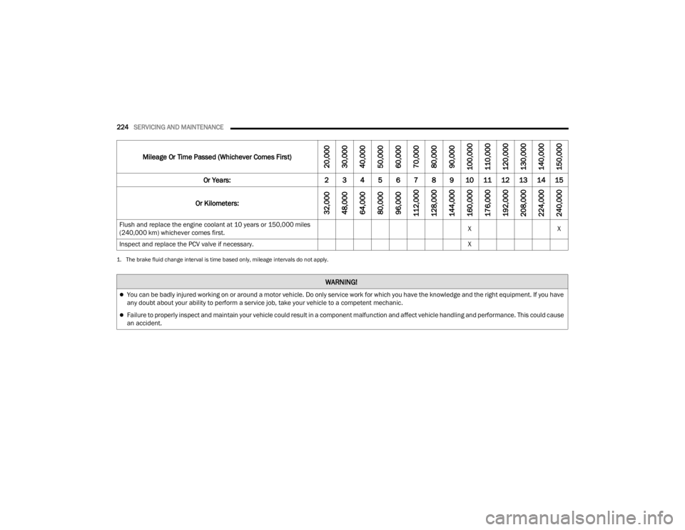
Flush and replace the engine coolant at 10 years or 150,000 miles
(240,000 km) whichever comes first. X
X
Inspect and replace the PCV valve if necessary. X
1. The brake fluid change interval is time based only, mileage intervals do not apply.
WARNING!
ï¬You can be badly injured working on or around a motor vehicle. Do only service work for which you have the knowledge and the right equipment. If you have
any doubt about your ability to perform a service job, take your vehicle to a competent mechanic.
ï¬Failure to properly inspect and maintain your vehicle could result in a component malfunction and affect vehicle handling and performance. This could cause
an accident.
Mileage Or Time Passed (Whichever Comes First)
20,000
30,000
40,000
50,000
60,000
70,000
80,000
90,000
100,000
110,000
120,000
130,000
140,000
150,000
Or Years: 2 3 4 5 6 7 8 9 10 11 12 13 14 15
Or Kilometers:
32,000
48,000
64,000
80,000
96,000
112,000
128,000
144,000
160,000
176,000
192,000
208,000
224,000
240,000
23_VF_OM_EN_USC_t.book Page 224
Page 227 of 296

SERVICING AND MAINTENANCE225
ENGINE COMPARTMENT
3.6L ENGINE
1 â Washer Fluid Reservoir Cap 5 â Engine Oil Dipstick
2 â Brake Fluid Reservoir Cap 6 â Coolant Reservoir Cap
3 â Engine Air Cleaner Filter 7 â Power Distribution Center (Fuses)
4 â Engine Oil Fill
8
23_VF_OM_EN_USC_t.book Page 225
Page 235 of 296

SERVICING AND MAINTENANCE233
COOLING SYSTEM
Coolant Checks
Check the engine coolant (antifreeze) protection
every 12 months (before the onset of freezing
weather, where applicable). If the engine coolant is
dirty, the system should be drained, flushed, and
refilled with fresh OAT coolant (conforming to
MS-12106) only by an authorized dealer. Check
the front of the A/C condenser for any accumulation of bugs, leaves, etc. If dirty, clean by
gently spraying water from a garden hose vertically
down the face of the condenser.
Cooling System â Drain, Flush And Refill
NOTE:Some vehicles require special tools to add coolant
properly. Failure to fill these systems properly
could lead to severe internal engine damage. If any
coolant is needed to be added to the system
please contact an authorized dealer.
If the engine coolant (antifreeze) is dirty or
contains visible sediment, have an authorized
dealer clean and flush with OAT coolant
(conforming to MS.90032).
For the proper maintenance intervals
Ãpage 222.
Selection Of Coolant
For further information à page 273.
NOTE:
ï¬Mixing of engine coolant (antifreeze) other than
specified Organic Additive Technology (OAT)
engine coolant, may result in engine damage
and may decrease corrosion protection. OAT
engine coolant is different and should not be
mixed with Hybrid Organic Additive Technology
(HOAT) engine coolant or any âglobally compat -
ibleâ coolant. If a non-OAT engine coolant is
introduced into the cooling system in an emer -
gency, the cooling system will need to be drained, flushed, and refilled with fresh OAT
coolant (conforming to MS.90032), by an autho
-
rized dealer as soon as possible.
ï¬Do not use water alone or alcohol-based engine
coolant products. Do not use additional rust
inhibitors or antirust products, as they may not
be compatible with the radiator engine coolant
and may plug the radiator.
ï¬This vehicle has not been designed for use with
propylene glycol-based engine coolant. Use of
propylene glycol-based engine coolant is not
recommended.
ï¬Some vehicles require special tools to add
coolant properly. Failure to fill these systems
properly could lead to severe internal engine
damage. If any coolant is needed to be added to
the system please contact an authorized dealer.
Adding Coolant
The vehicle has been built with an improved engine
coolant (OAT coolant conforming to MS.90032)
that allows extended maintenance intervals.
This engine coolant (antifreeze) can be used up to
10 years or 150,000 miles (240,000 km) before
replacement. To prevent reducing this extended
maintenance period, it is important to use the
same engine coolant (OAT coolant conforming to
MS.90032) throughout the life of your vehicle.
WARNING!
ï¬You or others can be badly burned by hot
engine coolant (antifreeze) or steam from your
radiator. If you see or hear steam coming from
under the hood, do not open the hood until the
radiator has had time to cool. Never open a
cooling system pressure cap when the radi -
ator or coolant bottle is hot.
ï¬Keep hands, tools, clothing, and jewelry away from
the radiator cooling fan when the hood is raised.
The fan starts automatically and may start at any
time, whether the engine is running or not.
ï¬When working near the radiator cooling fan,
disconnect the fan motor lead and turn the
ignition to the OFF mode. The fan is tempera -
ture controlled and can start at any time the
ignition is in the ON mode.
8
23_VF_OM_EN_USC_t.book Page 233