rear view mirror RAM PROMASTER 2023 Owners Manual
[x] Cancel search | Manufacturer: RAM, Model Year: 2023, Model line: PROMASTER, Model: RAM PROMASTER 2023Pages: 296, PDF Size: 12.31 MB
Page 4 of 296
2
INTRODUCTION
SYMBOLS KEY ...........................................................8
VAN CONVERSIONS/CAMPERS ..............................8
VEHICLE MODIFICATIONS/ALTERATIONS .............8
SYMBOL GLOSSARY.................................................9
GETTING TO KNOW YOUR VEHICLE
KEYS ....................................................................... 13 Key Fob .............................................................13
SENTRY KEY ........................................................... 16
IGNITION SWITCH .................................................. 16
Keyless Enter ‘n Go™ Ignition .........................16
REMOTE START — IF EQUIPPED .......................... 18
How To Use Remote Start ................................18
To Exit Remote Start Mode .............................19
Remote Start Defrost Mode Activation —
If Equipped........................................................19
Remote Start Comfort Systems —
If Equipped........................................................19
Remote Start Windshield Wiper De-Icer
Activation — If Equipped ..................................19
Remote Start Abort Message ..........................20
VEHICLE SECURITY SYSTEM — IF EQUIPPED .... 20
To Arm The System ..........................................20
To Disarm The System .....................................20
Rearming Of The System .................................20
Security System Manual Override ...................21 DOORS ....................................................................21
Power Door Locks ...........................................21
Auto Unlock Doors............................................22
Keyless Enter ‘n Go™ — Passive Entry ...........22
Automatic Door Locks ......................................23
STEERING WHEEL ..................................................23
Telescoping Steering Column..........................23
SEATS ......................................................................23
Manual Adjustments ........................................24
Heated Seats — If Equipped ............................26
Fold Down Tray — If Equipped .........................27
Adjustable Armrests — If Equipped .................27
Head Restraints ..............................................28
UCONNECT VOICE RECOGNITION —
IF EQUIPPED ...........................................................29
Introducing Voice Recognition.........................29
Basic Voice Commands ...................................29
Get Started .......................................................29
Additional Information .....................................30
MIRRORS ...............................................................30
Inside Rearview Mirror .....................................30
Outside Mirrors ................................................31
Outside Mirrors With Turn Signal And
Approach Lighting — If Equipped.....................31
Power Mirrors — If Equipped ...........................32
Power Folding Outside Mirrors —
If Equipped........................................................32
Heated Mirrors — If Equipped..........................33 EXTERIOR LIGHTS.................................................. 33
Multifunction Lever ......................................... 33
Headlights ........................................................ 33
Daytime Running Lights (DRLs) —
If Equipped ...................................................... 33
High/Low Beam Switch .................................. 34
Automatic High Beam Headlamp Control —
If Equipped .......................................................34
Flash-To-Pass .................................................. 34
Automatic Headlights — If Equipped .............. 34
Parking Lights .................................................. 34
Headlight Delay ................................................ 34
Fog Lights — If Equipped ................................. 35
Turn Signals...................................................... 35
Lane Change Assist..........................................35
Battery Saver .................................................... 35
INTERIOR LIGHTS ................................................. 36
Courtesy Lights.................................................36
Illuminated Entry — If Equipped ...................... 38
WIPERS AND WASHERS ...................................... 38
Windshield Wiper Operation ........................... 39
Rain Sensing Wipers — If Equipped ................39
CLIMATE CONTROLS ............................................ 40
Manual Climate Control Descriptions And
Functions .......................................................... 40
Additional Rear Climate Control —
If Equipped .......................................................43
Operating Tips .................................................. 43
23_VF_OM_EN_USC_t.book Page 2
Page 32 of 296
30GETTING TO KNOW YOUR VEHICLE
ADDITIONAL INFORMATION
© 2022 FCA US LLC. All rights reserved. Mopar and
Uconnect are registered trademarks and Mopar
Owner Connect is a trademark of FCA US LLC.
SiriusXM® and all related marks and logos are
trademarks of SiriusXM® Radio Inc. Ú page 280.
For Uconnect system support, call
1-877-855-8400 (24 hours a day 7 days a week)
or visit
DriveUconnect.com (US) or DriveUconnect.ca (Canada).
MIRRORS
INSIDE REARVIEW MIRROR
Manual Mirror — If Equipped
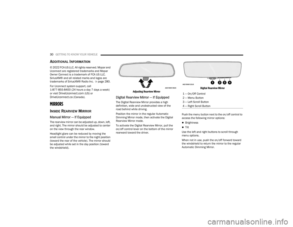
The rearview mirror can be adjusted up, down, left,
and right. The mirror should be adjusted to center
on the view through the rear window.
Headlight glare can be reduced by moving the
small control under the mirror to the night position
(toward the rear of the vehicle). The mirror should
be adjusted while set in the day position (toward
the windshield).
Adjusting Rearview Mirror
Digital Rearview Mirror — If Equipped
The Digital Rearview Mirror provides a high
definition, wide and unobstructed view of the
road behind while driving.
Position the mirror in the regular Automatic
Dimming Mirror mode, then activate the Digital
Rearview Mirror mode.
To activate the Digital Rearview Mirror, pull the
on/off control lever on the bottom of the mirror
rearward toward the driver.
Digital Rearview Mirror
Push the menu button next to the on/off control to
access the following mirror options:
Brightness
Tilt
Use the left and right buttons to scroll through
menu options.
When not in use, push the on/off forward toward
the windshield to return the mirror to the regular
Automatic Dimming Mirror.
1 — On/Off Control
2 — Menu Button
3 — Left Scroll Button
4 — Right Scroll Button
23_VF_OM_EN_USC_t.book Page 30
Page 33 of 296
GETTING TO KNOW YOUR VEHICLE31
NOTE:The Digital Rearview Mirror is not as effective when
driving in the following conditions:
Nighttime in low light applications
Bad weather conditions (e.g. extreme haze,
snow/slush)
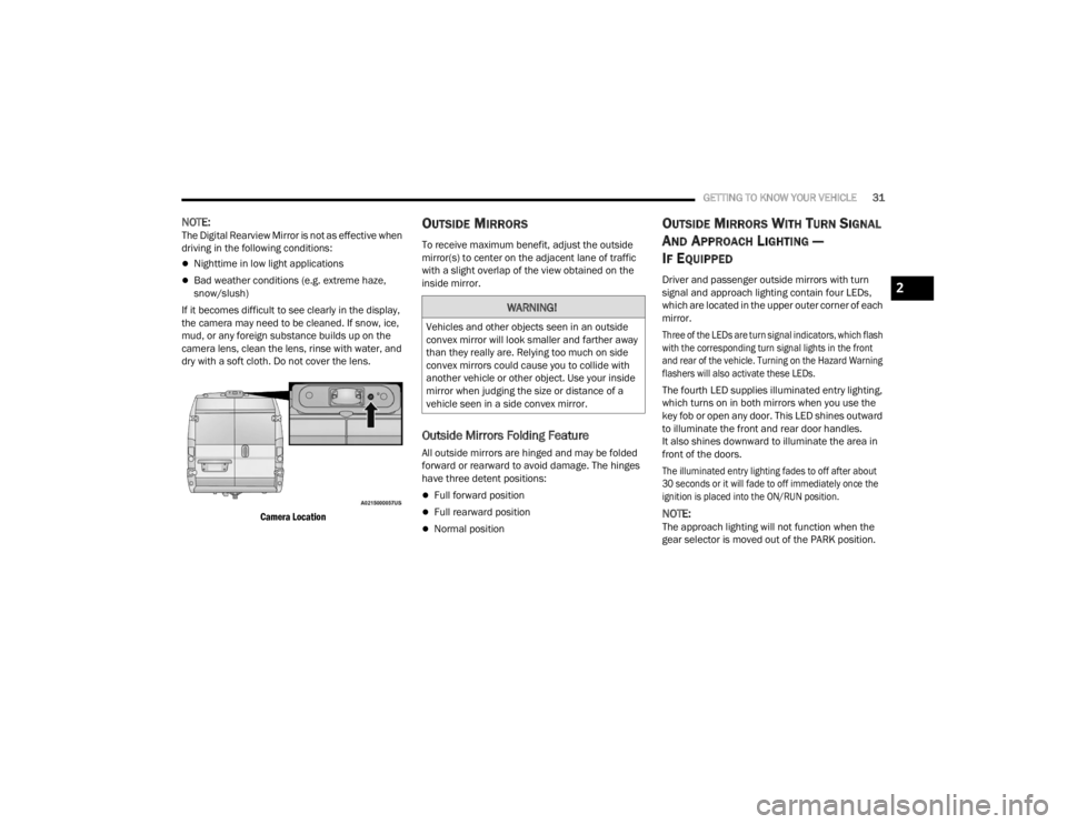
If it becomes difficult to see clearly in the display,
the camera may need to be cleaned. If snow, ice,
mud, or any foreign substance builds up on the
camera lens, clean the lens, rinse with water, and
dry with a soft cloth. Do not cover the lens.
Camera Location
OUTSIDE MIRRORS
To receive maximum benefit, adjust the outside
mirror(s) to center on the adjacent lane of traffic
with a slight overlap of the view obtained on the
inside mirror.
Outside Mirrors Folding Feature
All outside mirrors are hinged and may be folded
forward or rearward to avoid damage. The hinges
have three detent positions:
Full forward position
Full rearward position
Normal position
OUTSIDE MIRRORS WITH TURN SIGNAL
A
ND APPROACH LIGHTING —
I
F EQUIPPED
Driver and passenger outside mirrors with turn
signal and approach lighting contain four LEDs,
which are located in the upper outer corner of each
mirror.
Three of the LEDs are turn signal indicators, which flash
with the corresponding turn signal lights in the front
and rear of the vehicle. Turning on the Hazard Warning
flashers will also activate these LEDs.
The fourth LED supplies illuminated entry lighting,
which turns on in both mirrors when you use the
key fob or open any door. This LED shines outward
to illuminate the front and rear door handles.
It also shines downward to illuminate the area in
front of the doors.
The illuminated entry lighting fades to off after about
30 seconds or it will fade to off immediately once the
ignition is placed into the ON/RUN position.
NOTE:The approach lighting will not function when the
gear selector is moved out of the PARK position.
WARNING!
Vehicles and other objects seen in an outside
convex mirror will look smaller and farther away
than they really are. Relying too much on side
convex mirrors could cause you to collide with
another vehicle or other object. Use your inside
mirror when judging the size or distance of a
vehicle seen in a side convex mirror.
2
23_VF_OM_EN_USC_t.book Page 31
Page 98 of 296
96STARTING AND OPERATING
NOTE:
If the “ACC Front Radar Sensor Temporarily
Blinded” message occurs frequently (e.g. more
than once on every trip) without any snow, rain,
mud, or other obstruction, have the radar
sensor realigned at an authorized dealer.
Installing a snowplow, front-end protector, an
aftermarket grille or modifying the grille is not
recommended. Doing so may block the sensor
and inhibit ACC operation.
“ACC LIMITED FUNCTIONALITY CAMERA
BLOCKED” WARNING
The “ACC Limited Functionality Camera Blocked”
warning will display and a chime will sound when
conditions temporarily limit system performance.
This most often occurs at times of poor visibility,
such as in snow or heavy rain and fog. The ACC
system may also become temporarily blinded due
to obstructions, such as mud, dirt, or ice on
windshield and fog on the inside of glass. In these
cases, the instrument cluster display will read
“ACC Limited Functionality Camera Blocked” and
the system will have degraded performance. This message can sometimes be displayed while
driving in adverse weather conditions. The ACC
system will recover after the vehicle has left these
areas. Under rare conditions, when the camera is
not tracking any vehicles or objects in its path this
warning may temporarily occur.
If weather conditions are not a factor, the driver
should examine the windshield and the camera
located on the back side of the inside rearview
mirror. They may require cleaning or removal of an
obstruction.
When the condition that created limited functionality
is no longer present, the system will return to full
functionality.
NOTE:If the “ACC Limited Functionality Camera Blocked”
message occurs frequently (e.g. more than once
on every trip) without any snow, rain, mud, or other
obstruction, have the windshield and forward
facing camera inspected at an authorized dealer.
SERVICE ACC WARNING
If the system turns off, and the instrument cluster
display reads “ACC Unavailable Service Required” or
“Cruise Unavailable Service Required”, there may be an
internal system fault or a temporary malfunction that
limits ACC functionality. Although the vehicle is still
drivable under normal conditions, ACC will be
temporarily unavailable. If this occurs, try activating
ACC again later, following an ignition cycle. If the
problem persists, see an authorized dealer.
Precautions While Driving With ACC
In certain driving situations, ACC may have
detection issues. In these cases, ACC may brake
late or unexpectedly. The driver needs to stay alert
and may need to intervene. The following are
examples of these types of situations:
TOWING A TRAILER
Towing a trailer is not recommended when
using ACC.
23_VF_OM_EN_USC_t.book Page 96
Page 122 of 296
120STARTING AND OPERATING
NOTE:
If snow, ice, mud, or any foreign substance builds up
on the camera lens, clean the lens, rinse with water,
and dry with a soft cloth. Do not cover the lens.
SURROUND VIEW CAMERA SYSTEM —
IF EQUIPPED
Your vehicle may be equipped with the Surround View
Camera system that allows you to see an on-screen
image of the surroundings and Top View of your vehicle
whenever the gear selector is put into REVERSE or a
different view is selected through the touchscreen
buttons. The Top View of the vehicle will show which
doors are open. The image will be displayed on the
touchscreen display along with a caution note “Check
Entire Surroundings” across the top of the screen. After five seconds, this note will disappear. The Surround
View Camera system is comprised of four sequential
cameras located in the front grille, rear Center High
Mounted Stop Lamp (CHMSL), and side mirrors.
NOTE:The Surround View Camera system has program
-
mable settings that may be selected through the
Uconnect system Ú page 134.
When the vehicle is shifted into REVERSE, the Rear
View and Top View is the default view of the
system.
When the vehicle is shifted out of REVERSE with
camera delay turned on, the camera image will
continue to be displayed for up to 10 seconds unless
the vehicle speed exceeds 8 mph (13 km/h), the
vehicle is shifted into PARK, or the ignition is placed in
the OFF position. There is a touchscreen X button to
disable the display of the camera image.
When the vehicle is shifted out of REVERSE with
camera delay turned off, the Surround View system
is exited and the last known screen appears again.
Whenever the Rear View Camera image is
activated through the Back Up Camera button
in the Controls menu, and the vehicle speed is
greater than, or equal to, 8 mph (13 km/h), a
display timer for the image is initiated. The image
will continue to be displayed until the display timer
exceeds 10 seconds.
NOTE:
If the vehicle speed remains below 8 mph
(13 km/h), the Rear View Camera image will
be displayed continuously until deactivated via
the touchscreen X button, the transmission is
shifted into PARK, or the ignition is placed in the
OFF position.
The touchscreen X button to disable display of
the camera image is made available ONLY when
the vehicle is not in REVERSE.
When enabled, active guidelines are overlaid on
the image to illustrate the width of the vehicle,
including the side view mirrors and its projected
back up path based on the steering wheel position.
Different colored zones indicate the distance to
the rear of the vehicle.
The following table shows the approximate
distances for each zone:
CAUTION!
To avoid vehicle damage, ParkView should
only be used as a parking aid. The ParkView
camera is unable to view every obstacle or
object in your drive path.
To avoid vehicle damage, the vehicle must be
driven slowly when using ParkView to be able
to stop in time when an obstacle is seen. It is
recommended that the driver look frequently
over his/her shoulder when using ParkView.
Zone Distance To The Rear Of The
Vehicle
Red 0 - 1 ft (0 - 30 cm)
Yellow 1 ft - 6.5 ft (30 cm - 2 m) Green 6.5 ft or greater (2 m or greater)
23_VF_OM_EN_USC_t.book Page 120
Page 123 of 296

STARTING AND OPERATING121
Modes Of Operation
Manual activation of the Surround View system is
selected by pressing the Surround View Camera
button located in the Controls screen within the
Uconnect system.
Top View
The Top View will show in the Uconnect system with
Rear View or Front View in a split screen display.
There are integrated ParkSense arcs in the image
at the front and rear of the vehicle. The arcs will
change color from yellow to red corresponding the
distance zones to the oncoming object.
Surround View Camera View
NOTE:
Front tires will be in image when the tires are
turned.
Due to wide angle cameras in the mirrors, the
image will appear distorted.
Top View will show which sliding doors are open.
Open front doors will remove outside image.
Rear View This is the default view of the system in
REVERSE and is always paired with the
Top View of the vehicle with optional
active guidelines for the projected path
when enabled.
Rear Cross Path View
Pressing the Rear Cross Path button will
give the driver a wider angle view of the
Rear View. The Top View will be disabled
when this is selected.
Front View The Front View will show you what is
immediately in front of the vehicle and is
always paired with the Top View of the
vehicle.
Front Cross Path View Pressing the Front Cross Path button will
give the driver a wider angle view of the
Front View. The Top View will be disabled
when this is selected.
Back Up Camera View Pressing the Back Up Camera button will
provide a full screen rear view.
NOTE:If the Back Up Camera was selected through the
Surround View Camera menu, exiting out of screen
display will return to the Surround View menu.
If the Back Up Camera was manually activated
through the Controls menu of the Uconnect
system, exiting out of the display screen will
return to the Controls menu.
Deactivation
The system can be deactivated under the following
conditions:
The speed of the vehicle is greater than
8 mph (13 km/h).
The vehicle shifted into PARK.
The vehicle is in any gear other than REVERSE
and the touchscreen X button is pressed.
The camera delay system is turned off manually
through the Uconnect Settings Ú page 134.
NOTE:
If snow, ice, mud, or any foreign substance
builds up on the camera lenses, clean the
lenses, rinse with water, and dry with a soft
cloth. Do not cover the lenses.
If a malfunction with the system has occurred,
see an authorized dealer.
4
23_VF_OM_EN_USC_t.book Page 121
Page 160 of 296
158SAFETY
If the driving style indicates that the driver is
unable to follow the road trajectory and respect the
horizontal lane markings while within the operating
speed range of the system, a pop up will display on
the instrument cluster display to suggest that the
driver should stop for a break. An audible signal
will also sound.
If the driver accepts the suggestion provided by the
system by pushing the “OK” button on the left side
of the steering wheel, the message will disappear
from the display.
If the driver
does not acknowledge
the warning, it will
be displayed for 60 seconds and then disappear.
NOTE:In the event of a DDD system failure, a dedicated
message will appear in the instrument cluster
display.
DDD Warning Message
AUXILIARY DRIVING SYSTEMS
BLIND SPOT MONITORING (BS M) —
I
F EQUIPPED
The BSM system uses two radar sensors, located
inside the taillights, to detect highway licensable
vehicles (automobiles, trucks, motorcycles, etc.)
that enter the blind spot zones from the rear/front/
side of the vehicle.
Rear Detection Zones
When the vehicle is started, the BSM Warning Light will
momentarily illuminate in both outside rearview mirrors
to let the driver know that the system is operational.
The BSM system sensors operate when the vehicle is in
any forward gear and enters standby mode when the
vehicle is in PARK. The BSM detection zone covers approximately one lane
width on both sides of the vehicle 12 ft (3.8 m). The
zone length starts at the outside rearview mirror and
extends approximately 10 ft (3 m) beyond the rear
fascia/bumper of the vehicle. The BSM system
monitors the detection zones on both sides of the
vehicle when the vehicle speed reaches approximately
6 mph (10 km/h) or higher and will alert the driver of
vehicles in these areas.
NOTE:
The BSM system DOES NOT alert the driver
about rapidly approaching vehicles that are
outside the detection zones.
The Blind Spot Monitoring (BSM) system may
experience dropouts (blinking on and off) of the
side mirror warning indicator lamps when a
motorcycle or any small object remains at the
side of the vehicle for extended periods of time
(more than a couple of seconds).
23_VF_OM_EN_USC_t.book Page 158
Page 161 of 296

SAFETY159
The vehicle’s taillights, where the radar sensors
are located, must remain free of snow, ice, and
dirt/road contamination so that the BSM system
can function properly. Do not block the taillights
with foreign objects (bumper stickers, bicycle
racks, etc.).
Radar Sensor Locations
If the system detects degraded performance due
to contamination or foreign objects, a message will
warn you of a blocked sensor and the warning
indicators in the side view mirrors will be on.
The warning indicators will remain illuminated until
blockage clearing conditions are met. First clear
the taillights around the sensors of the blockage.
After removing the blockage, the following
procedure can be used to reset the system, cycle
the ignition from ON to OFF and then back ON. If the blockage message is still present after
cycling the ignition and driving in traffic, check
again for a blockage.
The BSM system notifies the driver of objects in the
detection zones by illuminating the BSM Warning
Light located in the outside mirrors in addition to
sounding an audible (chime) alert and reducing the
radio volume Ú
page 161.
Warning Light Location
The BSM system monitors the detection zone from
three different entry points (side, rear, front) while
driving to see if an alert is necessary. The BSM
system will issue an alert during these types of
zone entries.
Entering From The Side
Vehicles that move into your adjacent lanes from
either side of the vehicle.
Side Monitoring
Entering From The Rear
Vehicles that come up from behind your vehicle on
either side and enter the rear detection zone with
a relative speed of less than 30 mph (48 km/h).
Rear Monitoring
6
23_VF_OM_EN_USC_t.book Page 159
Page 163 of 296

SAFETY161
Rear Cross Path (RCP)
RCP is intended to aid the driver when backing out
of parking spaces where their vision of oncoming
vehicles may be blocked. Proceed slowly and
cautiously out of the parking space until the rear
end of the vehicle is exposed. The RCP system will
then have a clear view of the cross traffic, and if an
oncoming vehicle is detected, alert the driver.
RCP Detection Zones
RCP monitors the rear detection zones on both
sides of the vehicle, for objects that are moving
toward the side of the vehicle with a minimum
speed of approximately 3 mph (5 km/h), to objects
moving a maximum of approximately 20 mph
(32 km/h), such as in parking lot situations.
When RCP is on and the vehicle is in REVERSE (R),
the driver is alerted using both the visual and
audible alarms, including reducing the radio
volume.
NOTE:
In a parking lot situation, oncoming vehicles can be
blocked by vehicles parked on either side. If the
sensors are blocked by other structures or vehicles, the
system will not be able to alert the driver.
Blind Spot Modes
Blind Spot has three selectable modes of operation
that are available in the Uconnect system.
Blind Spot Alert Lights Only
When operating in Blind Spot Alert mode, the BSM
system will provide a visual alert in the appropriate side
view mirror based on a detected object. However, when
the system is operating in Rear Cross Path (RCP) mode,
the system will respond with both visual and audible
alerts when a detected object is present. Whenever an
audible alert is requested, the radio is muted.
Blind Spot Alert Lights/Chime
When operating in Blind Spot Alert Lights/Chime mode,
the BSM system will provide a visual alert in the
appropriate side view mirror based on a detected
object. If the turn signal is then activated, and it
corresponds to an alert present on that side of the
vehicle, an audible chime will also be sounded.
Whenever a turn signal and detected object are present
on the same side at the same time, both the visual and
audible alerts will be issued. In addition to the audible
alert the radio (if on) will also be muted.
NOTE:Whenever an audible alert is requested by the
BSM system, the radio is also muted.
When the system is in RCP, the system shall respond
with both visual and audible alerts when a detected
object is present. Whenever an audible alert is
requested, the radio is also muted. Turn/hazard signal
status is ignored; the RCP state always requests the
chime.
Blind Spot Alert Off
When the BSM system is turned off there will be no
visual or audible alerts from either the BSM or RCP
systems.
NOTE:The BSM system will store the current operating
mode when the vehicle is shut off. Each time the
vehicle is started the previously stored mode will
be recalled and used.
WARNING!
Rear Cross Path Detection (RCP) is not a backup
aid system. It is intended to be used to help a
driver detect an oncoming vehicle in a parking
lot situation. Drivers must be careful when
backing up, even when using RCP. Always check
carefully behind your vehicle, look behind you,
and be sure to check for pedestrians, animals,
other vehicles, obstructions, and blind spots
before backing up. Failure to do so can result in
serious injury or death.
6
23_VF_OM_EN_USC_t.book Page 161
Page 270 of 296

268SERVICING AND MAINTENANCE
LEATHER SURFACES
Mopar® Total Clean is specifically recommended
for leather upholstery.
Your leather upholstery can be best preserved by
regular cleaning with a damp soft cloth. Small particles
of dirt can act as an abrasive and damage the leather
upholstery and should be removed promptly with a
damp cloth. Stubborn soils can be removed easily with
a soft cloth and Mopar® Total Clean. Care should be
taken to avoid soaking your leather upholstery with any
liquid. Please do not use polishes, oils, cleaning fluids,
solvents, detergents, or ammonia-based cleaners to
clean your leather upholstery.
NOTE:If equipped with light colored leather, it tends to
show any foreign material, dirt, and fabric dye
transfer more so than darker colors. The leather is
designed for easy cleaning, and FCA recommends
Mopar® total care leather cleaner applied on a
cloth to clean the leather seats as needed.GLASS SURFACES
All glass surfaces should be cleaned on a
regular basis with Mopar® Glass Cleaner, or any
commercial household-type glass cleaner. Never
use an abrasive type cleaner. Use caution when
cleaning the inside rear window equipped with
electric defrosters or windows equipped with radio
antennas. Do not use scrapers or other sharp
instruments that may scratch the elements.
When cleaning the rearview mirror, spray cleaner
on the towel or cloth that you are using. Do not
spray cleaner directly on the mirror.
CAUTION!
Do not use alcohol and alcohol-based and/or
ketone-based cleaning products to clean leather
upholstery, as damage to the upholstery may
result.
23_VF_OM_EN_USC_t.book Page 268