air condition Ram ProMaster City 2018 Owner's Manual
[x] Cancel search | Manufacturer: RAM, Model Year: 2018, Model line: ProMaster City, Model: Ram ProMaster City 2018Pages: 180, PDF Size: 7.52 MB
Page 63 of 180
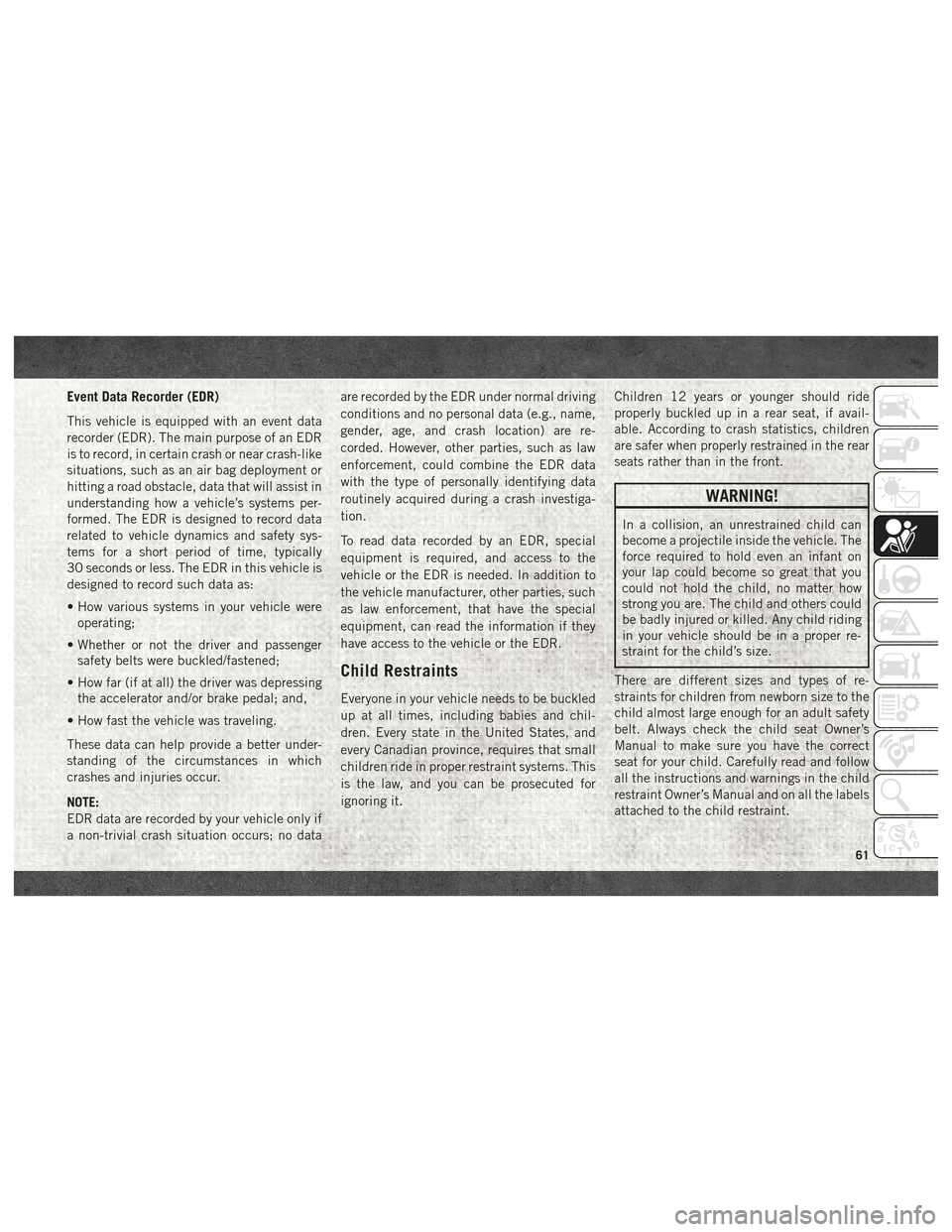
Event Data Recorder (EDR)
This vehicle is equipped with an event data
recorder (EDR). The main purpose of an EDR
is to record, in certain crash or near crash-like
situations, such as an air bag deployment or
hitting a road obstacle, data that will assist in
understanding how a vehicle’s systems per-
formed. The EDR is designed to record data
related to vehicle dynamics and safety sys-
tems for a short period of time, typically
30 seconds or less. The EDR in this vehicle is
designed to record such data as:
• How various systems in your vehicle wereoperating;
• Whether or not the driver and passenger safety belts were buckled/fastened;
• How far (if at all) the driver was depressing the accelerator and/or brake pedal; and,
• How fast the vehicle was traveling.
These data can help provide a better under-
standing of the circumstances in which
crashes and injuries occur.
NOTE:
EDR data are recorded by your vehicle only if
a non-trivial crash situation occurs; no data are recorded by the EDR under normal driving
conditions and no personal data (e.g., name,
gender, age, and crash location) are re-
corded. However, other parties, such as law
enforcement, could combine the EDR data
with the type of personally identifying data
routinely acquired during a crash investiga-
tion.
To read data recorded by an EDR, special
equipment is required, and access to the
vehicle or the EDR is needed. In addition to
the vehicle manufacturer, other parties, such
as law enforcement, that have the special
equipment, can read the information if they
have access to the vehicle or the EDR.
Child Restraints
Everyone in your vehicle needs to be buckled
up at all times, including babies and chil-
dren. Every state in the United States, and
every Canadian province, requires that small
children ride in proper restraint systems. This
is the law, and you can be prosecuted for
ignoring it.
Children 12 years or younger should ride
properly buckled up in a rear seat, if avail-
able. According to crash statistics, children
are safer when properly restrained in the rear
seats rather than in the front.
WARNING!
In a collision, an unrestrained child can
become a projectile inside the vehicle. The
force required to hold even an infant on
your lap could become so great that you
could not hold the child, no matter how
strong you are. The child and others could
be badly injured or killed. Any child riding
in your vehicle should be in a proper re-
straint for the child’s size.
There are different sizes and types of re-
straints for children from newborn size to the
child almost large enough for an adult safety
belt. Always check the child seat Owner’s
Manual to make sure you have the correct
seat for your child. Carefully read and follow
all the instructions and warnings in the child
restraint Owner’s Manual and on all the labels
attached to the child restraint.
61
Page 78 of 180
The best protection against carbon monoxide
entry into the vehicle body is a properly
maintained engine exhaust system.
Whenever a change is noticed in the sound of
the exhaust system, when exhaust fumes can
be detected inside the vehicle, or when the
underside or rear of the vehicle is damaged,
have a competent mechanic inspect the com-
plete exhaust system and adjacent body ar-
eas for broken, damaged, deteriorated, or
mispositioned parts. Open seams or loose
connections could permit exhaust fumes to
seep into the passenger compartment. In
addition, inspect the exhaust system each
time the vehicle is raised for lubrication or oil
change. Replace as required.
Safety Checks You Should Make
Inside The Vehicle
Seat Belts
Inspect the seat belt system periodically,
checking for cuts, frays, and loose parts.
Damaged parts must be replaced immedi-
ately. Do not disassemble or modify the sys-
tem.Front seat belt assemblies must be replaced
after a collision. Rear seat belt assemblies
must be replaced after a collision if they have
been damaged (i.e., bent retractor, torn web-
bing, etc.). If there is any question regarding
seat belt or retractor condition, replace the
seat belt.
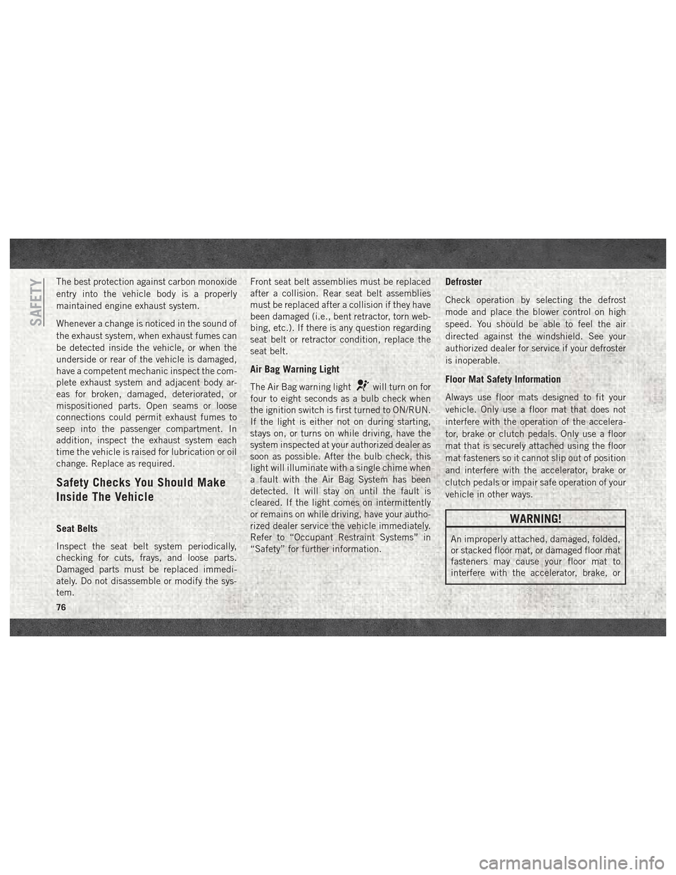
Air Bag Warning Light
The Air Bag warning lightwill turn on for
four to eight seconds as a bulb check when
the ignition switch is first turned to ON/RUN.
If the light is either not on during starting,
stays on, or turns on while driving, have the
system inspected at your authorized dealer as
soon as possible. After the bulb check, this
light will illuminate with a single chime when
a fault with the Air Bag System has been
detected. It will stay on until the fault is
cleared. If the light comes on intermittently
or remains on while driving, have your autho-
rized dealer service the vehicle immediately.
Refer to “Occupant Restraint Systems” in
“Safety” for further information.
Defroster
Check operation by selecting the defrost
mode and place the blower control on high
speed. You should be able to feel the air
directed against the windshield. See your
authorized dealer for service if your defroster
is inoperable.
Floor Mat Safety Information
Always use floor mats designed to fit your
vehicle. Only use a floor mat that does not
interfere with the operation of the accelera-
tor, brake or clutch pedals. Only use a floor
mat that is securely attached using the floor
mat fasteners so it cannot slip out of position
and interfere with the accelerator, brake or
clutch pedals or impair safe operation of your
vehicle in other ways.
WARNING!
An improperly attached, damaged, folded,
or stacked floor mat, or damaged floor mat
fasteners may cause your floor mat to
interfere with the accelerator, brake, or
SAFETY
76
Page 92 of 180
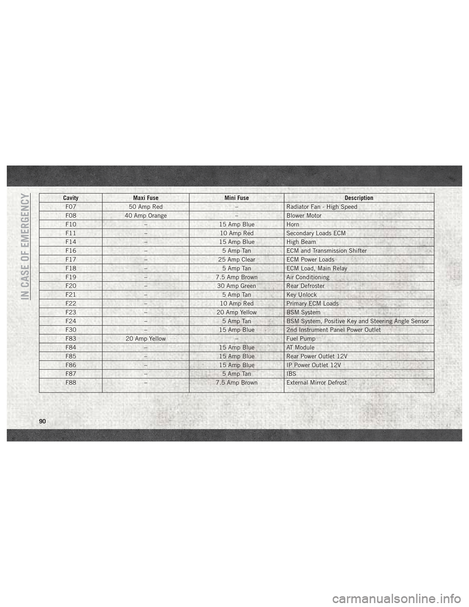
CavityMaxi Fuse Mini Fuse Description
F07 50 Amp Red –Radiator Fan - High Speed
F08 40 Amp Orange –Blower Motor
F10 –15 Amp BlueHorn
F11 –10 Amp RedSecondary Loads ECM
F14 –15 Amp BlueHigh Beam
F16 –5 Amp TanECM and Transmission Shifter
F17 –25 Amp ClearECM Power Loads
F18 –5 Amp TanECM Load, Main Relay
F19 –7.5 Amp Brown Air Conditioning
F20 –30 Amp Green Rear Defroster
F21 –5 Amp TanKey Unlock
F22 –10 Amp RedPrimary ECM Loads
F23 –20 Amp Yellow BSM System
F24 –5 Amp TanBSM System, Positive Key and Steering Angle Sensor
F30 –15 Amp Blue2nd Instrument Panel Power Outlet
F83 20 Amp Yellow –Fuel Pump
F84 –15 Amp BlueAT Module
F85 –15 Amp BlueRear Power Outlet 12V
F86 –15 Amp BlueIP Power Outlet 12V
F87 –5 Amp TanIBS
F88 –7.5 Amp Brown External Mirror Defrost
IN CASE OF EMERGENCY
90
Page 102 of 180

TIRE SERVICE KIT — IF EQUIPPED
Small punctures up to ¼” (6 mm) in the tire
tread can be sealed with Tire Service Kit.
Foreign objects (e.g., screws or nails) should
not be removed from the tire. Tire Service Kit
can be used in outside temperatures down to
approximately -4°F (-20°C).
This kit will provide a temporary tire seal,
allowing you to drive your vehicle up to 100
miles (160 km) with a maximum speed of
65 mph (106 km/h).
Tire Service Kit Storage
The Tire Service Kit is located under the
passenger seat.
Tire Service Kit Usage
If a tire is punctured, you can make a first
emergency repair using the Tire Service Kit
located under the passenger seat.
Tire punctures of up to 1/4” (6 mm) can be
repaired; the kit can be used in all weather
conditions. Do not remove the foreign object
from the punctured tire, i.e., screw or nail.Remove the Tire Service Kit from the vehicle,
take it out from the bag and place it near the
punctured tire. Screw the clear flexible filling
tube to the tire valve.
WARNING!
• Do not attempt to seal a tire on the side
of the vehicle closest to traffic. Pull far
enough off the road to avoid the danger
of being hit when using the Tire Service
Kit.
• Do not use Tire Service Kit or drive the
vehicle under the following circum-
stances:• If the puncture in the tire tread is
approximately 1/4 inch (6 mm) or
larger.
• If the tire has any sidewall damage.
• If the tire has any damage from
driving with extremely low tire pres-
sure.
• If the tire has any damage from
driving on a flat tire.
• If the wheel has any damage.
• If you are unsure of the condition of
the tire or the wheel.
• Keep Tire Service Kit away from open
flames or heat source.
• A loose Tire Service Kit thrown forward
in a collision or hard stop could endan-
ger the occupants of the vehicle. Always
Tire Service Kit Components
1 — Sealant Bottle
2 — Pressure Gauge
3 — Power Plug (Located Behind Stor-
age Door)
4 — Power Button
5 — Sealant Hose (Clear)
IN CASE OF EMERGENCY
100
Page 108 of 180
6. The vehicle may then be started inNEUTRAL.
7. Reinstall the gear selector boot.
IF YOUR ENGINE OVERHEATS
In any of the following situations, you can
reduce the potential for overheating by taking
the appropriate action.
• On the highways — slow down.
• In city traffic — while stopped, place the transmission in NEUTRAL, but do not in-
crease the engine idle speed while prevent-
ing vehicle motion with the brakes.
NOTE:
There are steps that you can take to slow
down an impending overheat condition:
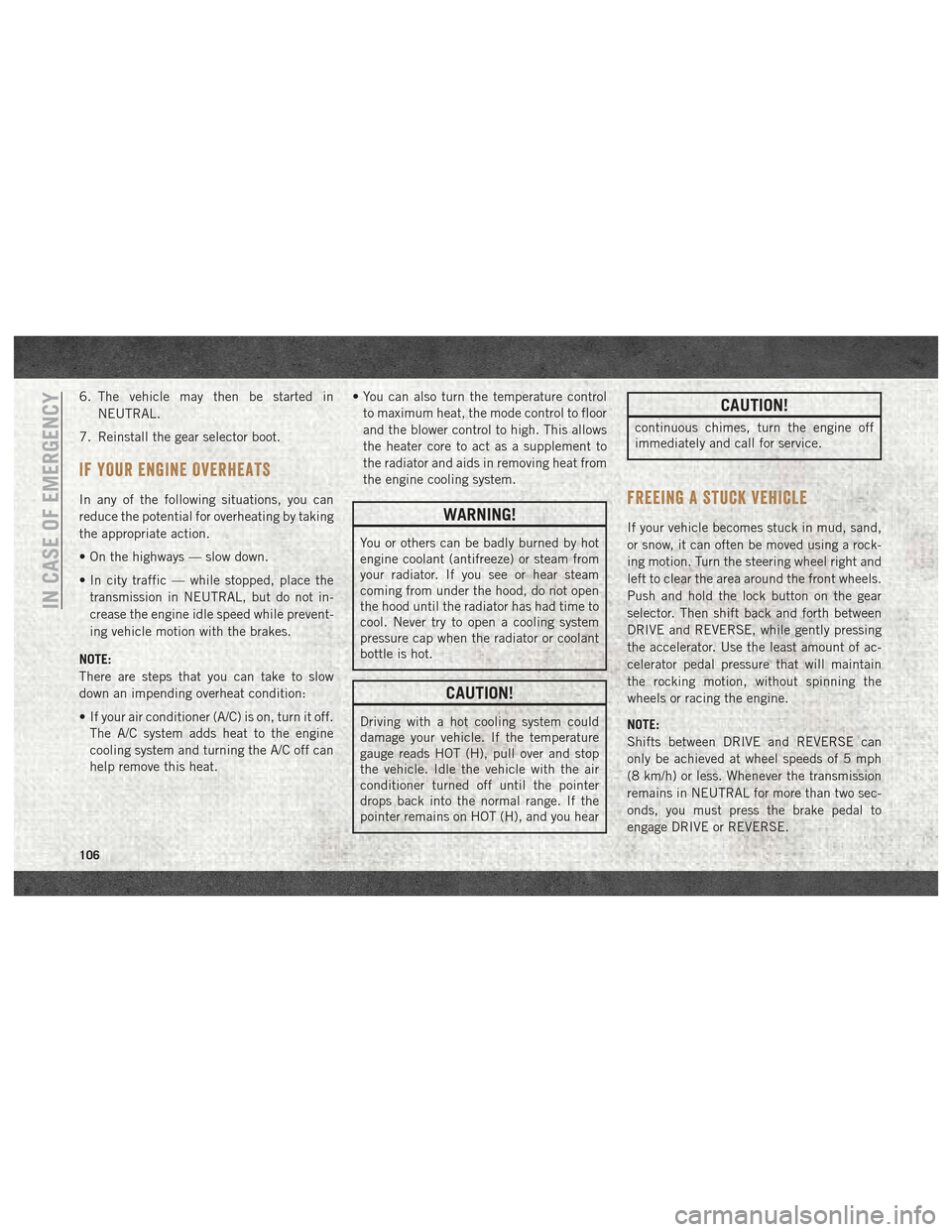
• If your air conditioner (A/C) is on, turn it off. The A/C system adds heat to the engine
cooling system and turning the A/C off can
help remove this heat. • You can also turn the temperature control
to maximum heat, the mode control to floor
and the blower control to high. This allows
the heater core to act as a supplement to
the radiator and aids in removing heat from
the engine cooling system.
WARNING!
You or others can be badly burned by hot
engine coolant (antifreeze) or steam from
your radiator. If you see or hear steam
coming from under the hood, do not open
the hood until the radiator has had time to
cool. Never try to open a cooling system
pressure cap when the radiator or coolant
bottle is hot.
CAUTION!
Driving with a hot cooling system could
damage your vehicle. If the temperature
gauge reads HOT (H), pull over and stop
the vehicle. Idle the vehicle with the air
conditioner turned off until the pointer
drops back into the normal range. If the
pointer remains on HOT (H), and you hear
CAUTION!
continuous chimes, turn the engine off
immediately and call for service.
FREEING A STUCK VEHICLE
If your vehicle becomes stuck in mud, sand,
or snow, it can often be moved using a rock-
ing motion. Turn the steering wheel right and
left to clear the area around the front wheels.
Push and hold the lock button on the gear
selector. Then shift back and forth between
DRIVE and REVERSE, while gently pressing
the accelerator. Use the least amount of ac-
celerator pedal pressure that will maintain
the rocking motion, without spinning the
wheels or racing the engine.
NOTE:
Shifts between DRIVE and REVERSE can
only be achieved at wheel speeds of 5 mph
(8 km/h) or less. Whenever the transmission
remains in NEUTRAL for more than two sec-
onds, you must press the brake pedal to
engage DRIVE or REVERSE.
IN CASE OF EMERGENCY
106
Page 110 of 180
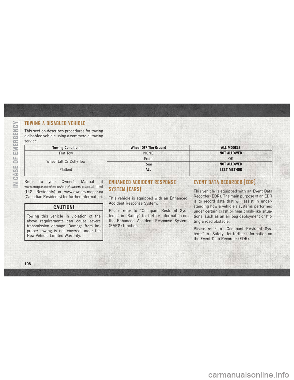
TOWING A DISABLED VEHICLE
This section describes procedures for towing
a disabled vehicle using a commercial towing
service.
Towing ConditionWheel OFF The Ground ALL MODELS
Flat Tow NONENOT ALLOWED
Wheel Lift Or Dolly Tow Front
OK
Rear NOT ALLOWED
Flatbed ALL
BEST METHOD
Refer to your Owner’s Manual at
www.mopar.com/en-us/care/owners-manual.html
(U.S. Residents) or www.owners.mopar.ca
(Canadian Residents) for further information.
CAUTION!
Towing this vehicle in violation of the
above requirements can cause severe
transmission damage. Damage from im-
proper towing is not covered under the
New Vehicle Limited Warranty.
ENHANCED ACCIDENT RESPONSE
SYSTEM (EARS)
This vehicle is equipped with an Enhanced
Accident Response System.
Please refer to “Occupant Restraint Sys-
tems” in “Safety” for further information on
the Enhanced Accident Response System
(EARS) function.
EVENT DATA RECORDER (EDR)
This vehicle is equipped with an Event Data
Recorder (EDR). The main purpose of an EDR
is to record data that will assist in under-
standing how a vehicle’s systems performed
under certain crash or near crash-like situa-
tions, such as an air bag deployment or hit-
ting a road obstacle.
Please refer to “Occupant Restraint Sys-
tems” in “Safety” for further information on
the Event Data Recorder (EDR).IN CASE OF EMERGENCY
108
Page 113 of 180
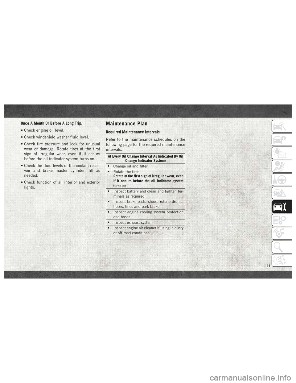
Once A Month Or Before A Long Trip:
• Check engine oil level.
• Check windshield washer fluid level.
• Check tire pressure and look for unusualwear or damage. Rotate tires at the first
sign of irregular wear, even if it occurs
before the oil indicator system turns on.
• Check the fluid levels of the coolant reser- voir and brake master cylinder, fill as
needed.
• Check function of all interior and exterior lights.Maintenance Plan
Required Maintenance Intervals
Refer to the maintenance schedules on the
following page for the required maintenance
intervals.
At Every Oil Change Interval As Indicated By Oil Change Indicator System:
• Change oil and filter
• Rotate the tires
Rotate at the first sign of irregular wear, even
if it occurs before the oil indicator system
turns on
• Inspect battery and clean and tighten ter- minals as required
• Inspect brake pads, shoes, rotors, drums, hoses, lines and park brake
• Inspect engine cooling system protection and hoses
• Inspect exhaust system
• Inspect engine air cleaner if using in dusty or off-road conditions
111
Page 114 of 180
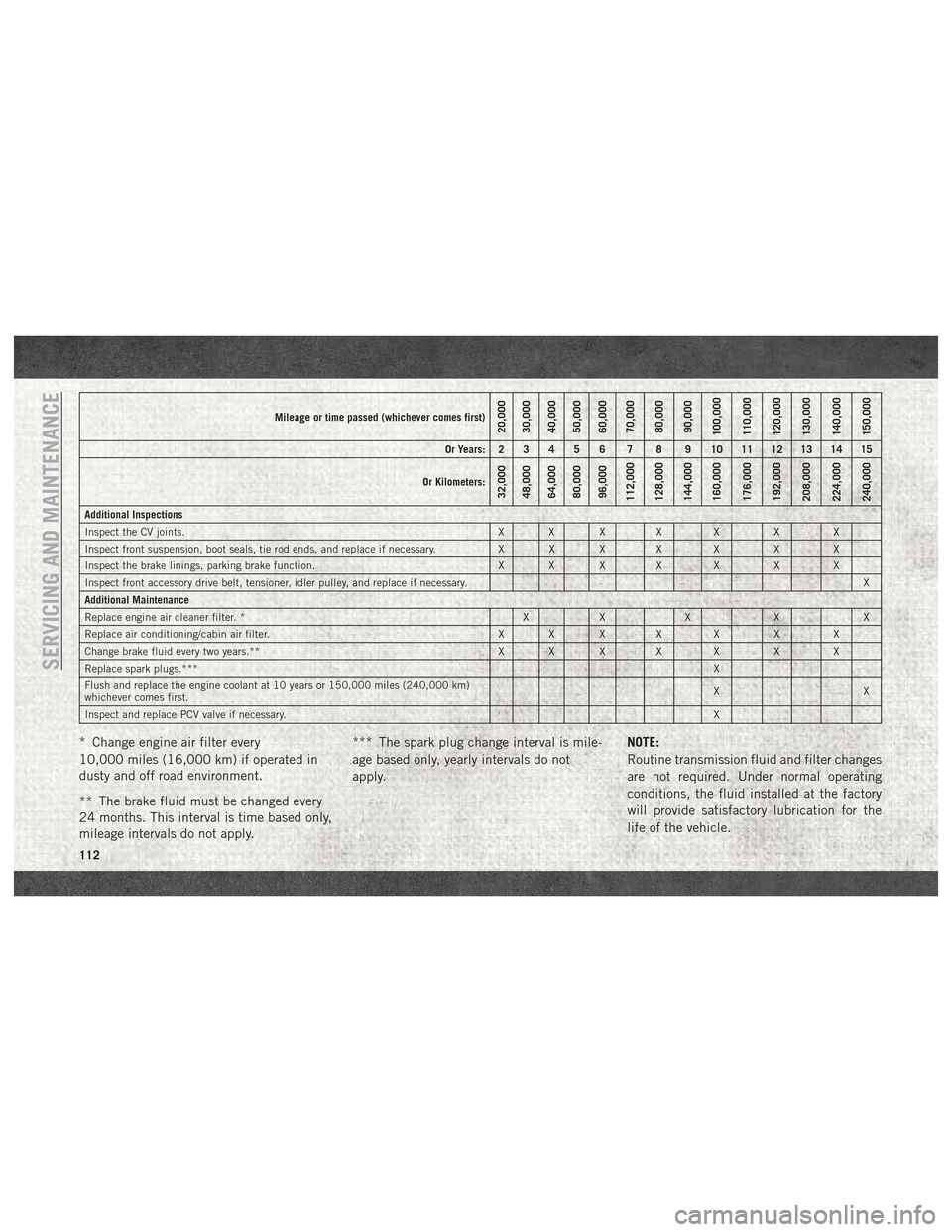
Mileage or time passed (whichever comes first)20,000
30,000
40,000
50,000
60,000
70,000
80,000
90,000
100,000
110,000
120,000
130,000
140,000
150,000
Or Years: 2 3 4 5 6 7 8 9 10 11 12 13 14 15
Or Kilometers:
32,000
48,000
64,000
80,000
96,000
112,000
128,000
144,000
160,000
176,000
192,000
208,000
224,000
240,000
Additional Inspections
Inspect the CV joints. X X X X X X X
Inspect front suspension, boot seals, tie rod ends, and replace if necessary. X X X X X X X
Inspect the brake linings, parking brake function. X X X X X X X
Inspect front accessory drive belt, tensioner, idler pulley, and replace if necessary. X
Additional Maintenance
Replace engine air cleaner filter. * X X X X X
Replace air conditioning/cabin air filter. X X X X X X X
Change brake fluid every two years.** X X X X X X X
Replace spark plugs.*** X
Flush and replace the engine coolant at 10 years or 150,000 miles (240,000 km)
whichever comes first. XX
Inspect and replace PCV valve if necessary. X
* Change engine air filter every
10,000 miles (16,000 km) if operated in
dusty and off road environment.
** The brake fluid must be changed every
24 months. This interval is time based only,
mileage intervals do not apply.*** The spark plug change interval is mile-
age based only, yearly intervals do not
apply.
NOTE:
Routine transmission fluid and filter changes
are not required. Under normal operating
conditions, the fluid installed at the factory
will provide satisfactory lubrication for the
life of the vehicle.
SERVICING AND MAINTENANCE
112
Page 126 of 180
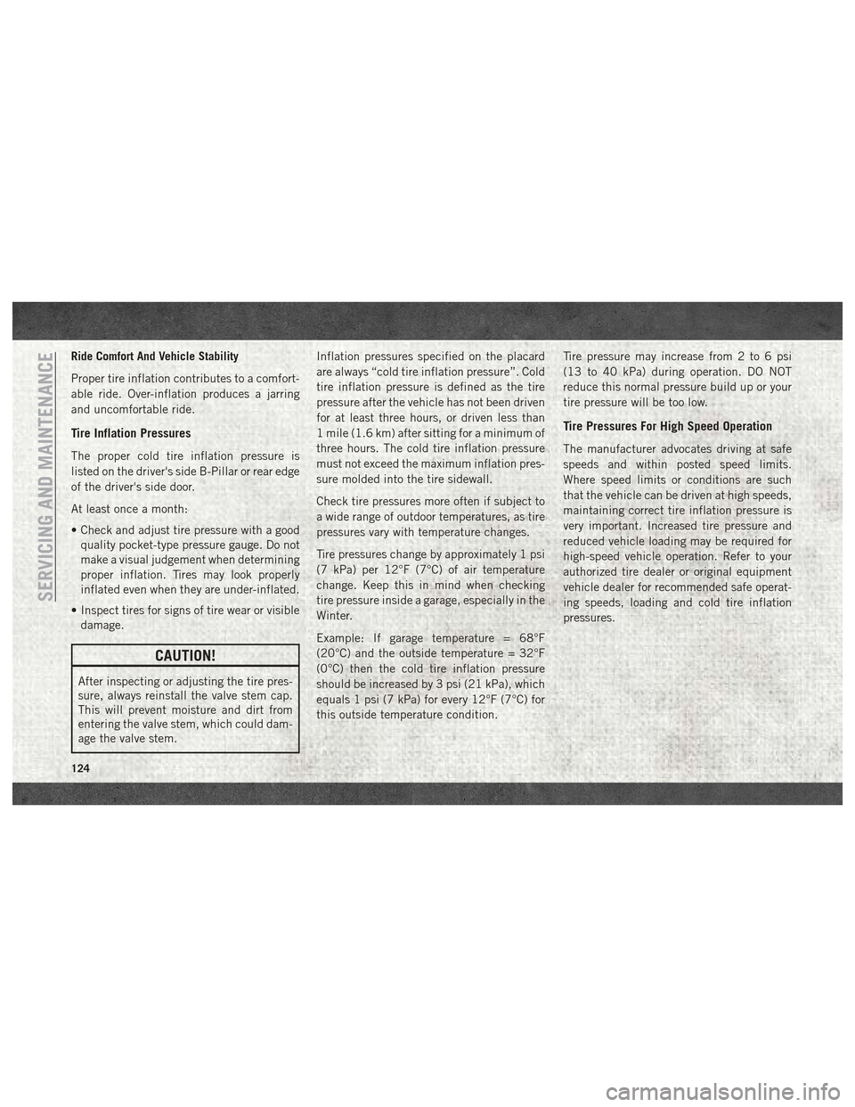
Ride Comfort And Vehicle Stability
Proper tire inflation contributes to a comfort-
able ride. Over-inflation produces a jarring
and uncomfortable ride.
Tire Inflation Pressures
The proper cold tire inflation pressure is
listed on the driver's side B-Pillar or rear edge
of the driver's side door.
At least once a month:
• Check and adjust tire pressure with a goodquality pocket-type pressure gauge. Do not
make a visual judgement when determining
proper inflation. Tires may look properly
inflated even when they are under-inflated.
• Inspect tires for signs of tire wear or visible damage.
CAUTION!
After inspecting or adjusting the tire pres-
sure, always reinstall the valve stem cap.
This will prevent moisture and dirt from
entering the valve stem, which could dam-
age the valve stem. Inflation pressures specified on the placard
are always “cold tire inflation pressure”. Cold
tire inflation pressure is defined as the tire
pressure after the vehicle has not been driven
for at least three hours, or driven less than
1 mile (1.6 km) after sitting for a minimum of
three hours. The cold tire inflation pressure
must not exceed the maximum inflation pres-
sure molded into the tire sidewall.
Check tire pressures more often if subject to
a wide range of outdoor temperatures, as tire
pressures vary with temperature changes.
Tire pressures change by approximately 1 psi
(7 kPa) per 12°F (7°C) of air temperature
change. Keep this in mind when checking
tire pressure inside a garage, especially in the
Winter.
Example: If garage temperature = 68°F
(20°C) and the outside temperature = 32°F
(0°C) then the cold tire inflation pressure
should be increased by 3 psi (21 kPa), which
equals 1 psi (7 kPa) for every 12°F (7°C) for
this outside temperature condition.
Tire pressure may increase from 2 to 6 psi
(13 to 40 kPa) during operation. DO NOT
reduce this normal pressure build up or your
tire pressure will be too low.
Tire Pressures For High Speed Operation
The manufacturer advocates driving at safe
speeds and within posted speed limits.
Where speed limits or conditions are such
that the vehicle can be driven at high speeds,
maintaining correct tire inflation pressure is
very important. Increased tire pressure and
reduced vehicle loading may be required for
high-speed vehicle operation. Refer to your
authorized tire dealer or original equipment
vehicle dealer for recommended safe operat-
ing speeds, loading and cold tire inflation
pressures.
SERVICING AND MAINTENANCE
124
Page 160 of 180
ments, such as aboard airplanes. If you are
unsure of restrictions, you are encouraged to
ask for authorization before turning on the
wireless radio.
This device complies with Part 15 of the FCC
Rules and with Industry Canada license-
exempt RSS standard(s). Operation is sub-
ject to the following two conditions:
1. This device may not cause harmfulinterference.
2. This device must accept any interference received, including interference that may
cause undesired operation.
NOTE:
Changes or modifications not expressly ap-
proved by the party responsible for compli-
ance could void the user’s authority to oper-
ate the equipment. NOTE:
• This equipment has been tested and found
to comply with the limits for a Class B
digital device, pursuant to Part 15 of the
FCC Rules. These limits are designed to
provide reasonable protection against
harmful interference in a residential instal-
lation. This equipment generates, uses and
can radiate radio frequency energy and, if
not installed and used in accordance with
the instructions, may cause harmful inter-
ference to radio communications. However,
there is no guarantee that interference will
not occur in a particular installation.
• If this equipment does cause harmful inter- ference to radio or television reception,
which can be determined by turning the
equipment off and on, the user is encour-
aged to try to correct the interference by
one or more of the following measures:
1. Increase the separation between the equipment and receiver.
2. Consult the dealer or an experienced radio technician for help.UCONNECT VOICE RECOGNITION
QUICK TIPS
Introducing Uconnect
Start using Uconnect Voice Recognition with
these helpful quick tips. It provides the key
Voice Commands and tips you need to know
to control your Uconnect system.
Key Features:
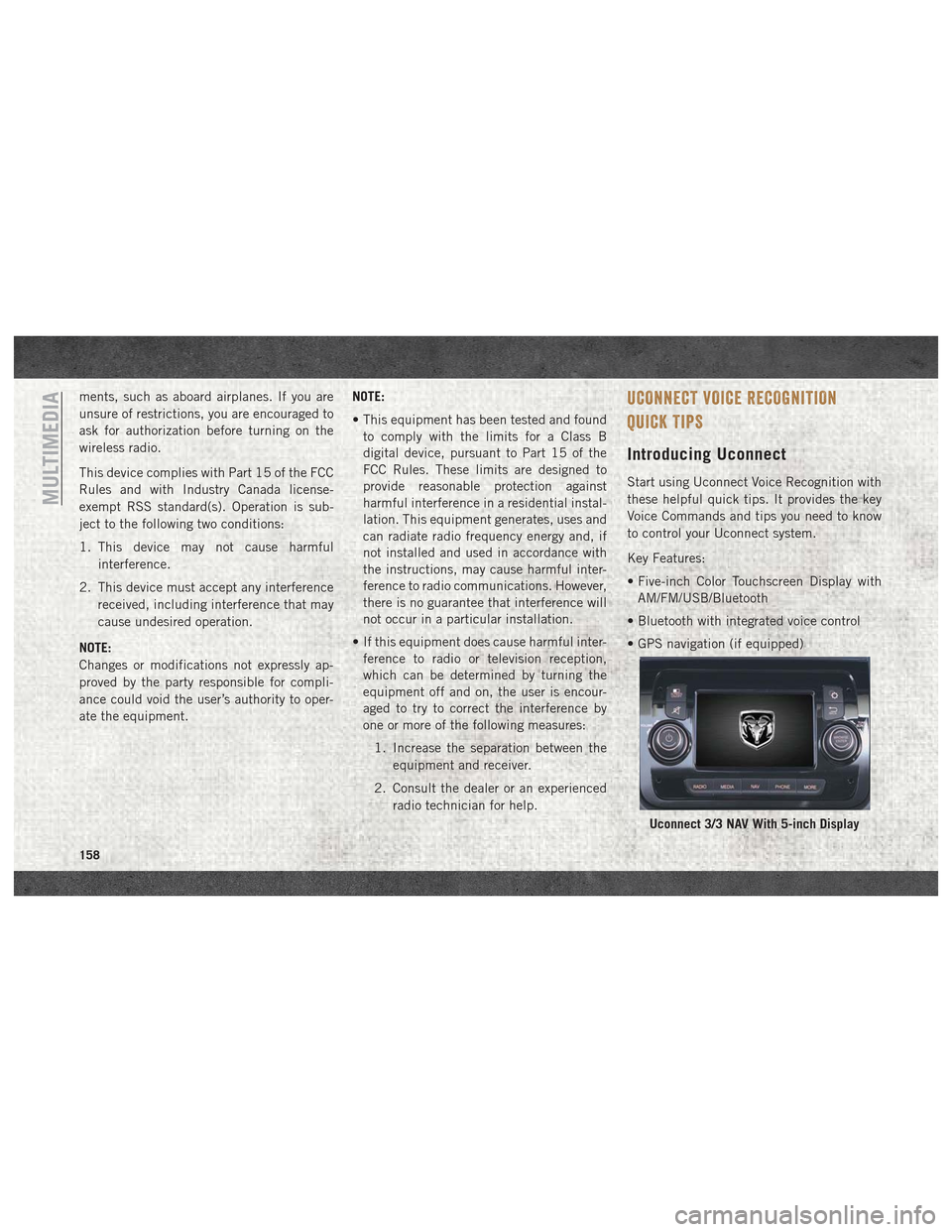
• Five-inch Color Touchscreen Display withAM/FM/USB/Bluetooth
• Bluetooth with integrated voice control
• GPS navigation (if equipped)
Uconnect 3/3 NAV With 5-inch Display
MULTIMEDIA
158