key Ram ProMaster City 2018 Owner's Manual
[x] Cancel search | Manufacturer: RAM, Model Year: 2018, Model line: ProMaster City, Model: Ram ProMaster City 2018Pages: 180, PDF Size: 7.52 MB
Page 46 of 180
Tire Pressure Monitoring Low Pressure
Warnings
The Tire Pressure Monitoring Telltale Light
will illuminate in the instrument cluster, an
audible chime will be activated, and the
“Check tire pressure” text message will dis-
play when one or more of the four active road
tire pressures are low. Should this occur, you
should stop as soon as possible, check the
inflation pressure of each tire on your vehicle,
and inflate each tire to the vehicle’s recom-
mended cold placard pressure value. The
system will automatically update and the Tire
Pressure Monitoring Light will extinguish
once the updated tire pressures have been
received. The vehicle may need to be driven
for up to 20 minutes above 15 mph
(24 km/h) to receive this information.
Check TPMS Warnings
The Tire Pressure Monitoring Telltale Light
will flash on and off for 75 seconds and
remain on solid when a system fault is de-
tected, an audible chime will be activated
and a proper text message will be displayed.
If the ignition key is cycled, this sequence
will repeat providing the system fault stillexists. The Tire Pressure Monitoring Telltale
Light will turn off when the fault condition no
longer exists. A system fault can occur with
any of the following scenarios:
1. Jamming due to electronic devices or driv-
ing next to facilities emitting the same
radio frequencies as the TPM sensors.
2. Installing some form of aftermarket win- dow tinting that affects radio wave
signals.
3. Snow or ice around the wheels or wheel housings.
4. Using tire chains on the vehicle.
5. Using wheels/tires not equipped with TPM sensors.
NOTE:
Your vehicle can be equipped with either Tire
Service Kit, compact spare tire or regular size
spare tire (with or without original TPMS
sensor).
1. Tire Service Kit (original tire sealant – if equipped): After fixing the punctured tire
with original tire sealant, the original situ-
ation will be restored, so system will turn
off the telltale during the normal drive. 2. Compact Spare Tire – if equipped: The
compact spare wheel is not equipped with
TPMS sensor. So when mounted, during
the normal drive the system will turn on
the telltale (flashing for approximately
75 sec. then remains solid). This condi-
tion persists until a wheel equipped with
original TPMS sensor has been mounted
on the vehicle.
3. Regular size spare tire (not equipped with TPMS sensor): When mounted, during the
normal drive the system will turn on the
telltale (flashing for approximately
75 sec. then remains solid). This condi-
tion persists until a wheel equipped with
original TPMS sensor has been mounted
on the vehicle. Then the system will be
restored and the telltale will turn off dur-
ing the normal drive.
4. Regular size spare tire (equipped with TPMS sensor): When mounted, the tell-
tale will turn off during the normal drive.
5. In all the above cases please check the replacement tire inflation pressure before
driving your vehicle.
SAFETY
44
Page 47 of 180
6. In case of tire replacement, if the vehicleis driven for short periods of time, then the
system can take a while to be restored.
NOTE:
For a correct Tire Pressure Monitoring behav-
ior, please wait for about 20 minutes in
key-off during each tire substitution.
General Information
This device complies with Part 15 of the FCC
rules and RSS 210 of Industry Canada. Op-
eration is subject to the following conditions:
1. This device may not cause harmful interference.
2. This device must accept any interference received, including interference that may
cause undesired operation.
NOTE:
Changes or modifications not expressly ap-
proved by the party responsible for compli-
ance could void the user’s authority to oper-
ate the equipment.
OCCUPANT RESTRAINT SYSTEMS
Some of the most important safety features in
your vehicle are the restraint systems:
Occupant Restraint Systems
• Seat Belt Systems
• Supplemental Restraint Systems (SRS) Air Bags
• Child Restraints
Some of the safety features described in this
section may be standard equipment on some
models, or may be optional equipment on
others. If you are not sure, ask your autho-
rized dealer.
Important Safety Precautions
Please pay close attention to the information
in this section. It tells you how to use your
restraint system properly, to keep you and
your passengers as safe as possible.
Here are some simple steps you can take to
minimize the risk of harm from a deploying
air bag: 1. Children 12 years old and under should
always ride buckled up in a vehicle with a
rear seat.
2. If a child from 2 to 12 years old (not in a rear-facing child restraint) must ride in
the front passenger seat, move the seat as
far back as possible and use the proper
child restraint. (Refer to “Child Re-
straints” in the section for further
information).
3. Children that are not big enough to wear the vehicle seat belt properly (refer to
“Child Restraints” in this section for fur-
ther information) should be secured in a
vehicle with a rear seat in child restraints
or belt-positioning booster seats. Older
children who do not use child restraints or
belt-positioning booster seats should ride
properly buckled up in a vehicle with a
rear seat.
4. Never allow children to slide the shoulder belt behind them or under their arm.
5. You should read the instructions provided with your child restraint to make sure that
you are using it properly.
45
Page 79 of 180
WARNING!
clutch pedals and cause a loss of vehicle
control. To prevent SERIOUS INJURY or
DEATH:
• ALWAYS securely attach
your floor
mat using the floor mat fasteners. DO
NOT install your floor mat upside down
or turn your floor mat over. Lightly pull to
confirm mat is secured using the floor
mat fasteners on a regular basis.
• ALWAYS REMOVE THE EXISTING
FLOOR MAT FROM THE VEHICLE
before installing any other floor mat.
NEVER install or stack an additional
floor mat on top of an existing floor mat.
• ONLY install floor mats designed to fit
your vehicle. NEVER install a floor mat
that cannot be properly attached and
secured to your vehicle. If a floor mat
needs to be replaced, only use a FCA
approved floor mat for the specific
make, model, and year of your vehicle.
WARNING!
• ONLY use the driver’s side floor mat onthe driver’s side floor area. To check for
interference, with the vehicle properly
parked with the engine off, fully depress
the accelerator, the brake, and the
clutch pedal (if present) to check for
interference. If your floor mat interferes
with the operation of any pedal, or is not
secure to the floor, remove the floor mat
from the vehicle and place the floor mat
in your trunk.
• ONLY use the passenger’s side floor mat
on the passenger’s side floor area.
• ALWAYS make sure objects cannot fall
or slide into the driver’s side floor area
when the vehicle is moving. Objects can
become trapped under accelerator,
brake, or clutch pedals and could cause
a loss of vehicle control.
• NEVER place any objects under the floor
mat (e.g., towels, keys, etc.). These ob-
WARNING!
jects could change the position of the
floor mat and may cause interference
with the accelerator, brake, or clutch
pedals.
• If the vehicle carpet has been removed
and re-installed, always properly attach
carpet to the floor and check the floor
mat fasteners are secure to the vehicle
carpet. Fully depress each pedal to
check for interference with the accelera-
tor, brake, or clutch pedals then re-
install the floor mats.
• It is recommended to only use mild soap
and water to clean your floor mats. After
cleaning, always check your floor mat
has been properly installed and is se-
cured to your vehicle using the floor mat
fasteners by lightly pulling mat.
77
Page 85 of 180
The Rear Back Up Camera can also be acti-
vated when the vehicle is not in REVERSE
through the Uconnect System. Refer to
“Uconnect 3/3 NAV With 5-inch Display”
supplement for further information.
NOTE:
If one of the rear cargo doors is not com-
pletely closed, the Back Up Camera cannot
provide an accurate image of the area behind
the vehicle. A dedicated message will appear
on the Uconnect display indicating the cam-
era is not in the correct position.The Camera Delay setting can be set to on/off
in the rear camera settings menu. When the
vehicle is shifted out of REVERSE and the
Camera Delay is turned off, the rear camera
mode is exited and the navigation or audio
screen appears on display again.
When the transmission is shifted out of RE-
VERSE, and Camera Delay is activated in the
menu screen, the camera image will continue
to be displayed for up to 10 seconds, unless
the speed of the vehicle is greater than 8 mph
(13 km/h), the transmission is in PARK, or
the ignition key is in the OFF position.The display of the camera image can be
enabled or disabled through the rear camera
setting menu item (Camera on/off).
When displayed, static grid lines will illus-
trate the width of the vehicle and will show
separate zones that will help indicate the
distance to the rear of the vehicle. The fol-
lowing table shows the approximate dis-
tances for each zone:
Zone
Distance To The Rear Of The Vehicle
Red 0-1ft(0-30cm)
Yellow 1 ft - 3 ft (30 cm - 1 m)
Green 3 ft or greater (1 m or greater)
WARNING!
Drivers must be careful when backing up
even when using the ParkView Rear Back
Up Camera. Always check carefully behind
your vehicle, and be sure to check for
pedestrians, animals, other vehicles, ob-
WARNING!
structions, or blind spots before backing
up. You are responsible for the safety of
your surroundings and must continue to
pay attention while backing up. Failure to
do so can result in serious injury or death.
CAUTION!
• To avoid vehicle damage, ParkView
should only be used as a parking aid.
The ParkView camera is unable to view
every obstacle or object in your drive
path.
83
Page 89 of 180
IN CASE OF EMERGENCY
BULB REPLACEMENT............88
Replacement Bulbs..............88
FUSES......................89
Underhood Fuses ...............89
Interior Fuses .................91
Central Unit Fuse Panel ...........92
JACKING AND TIRE CHANGING ......92
Jack Location.................93
Removing The Spare Tire ..........93
Preparations For Jacking ..........95Jacking Instructions
.............95
Vehicles With Alloy Wheels .........98
Vehicles Equipped With Wheel Covers. . .99
TIRE SERVICE KIT — IF EQUIPPED . .100
Tire Service Kit Storage ..........100
Tire Service Kit Usage ...........100
JUMP STARTING..............102
Preparations For Jump Starting ......102
Jump Starting Procedure ..........103
IGNITION KEY REMOVAL OVERRIDE . . .104 GEAR SELECTOR OVERRIDE
.......105
IF YOUR ENGINE OVERHEATS ......106
FREEING A STUCK VEHICLE .......106
TOWING A DISABLED VEHICLE .....108
ENHANCED ACCIDENT RESPONSE
SYSTEM (EARS) ...............108
EVENT DATA RECORDER (EDR) ......108
IN CASE OF EMERGENCY
87
Page 92 of 180
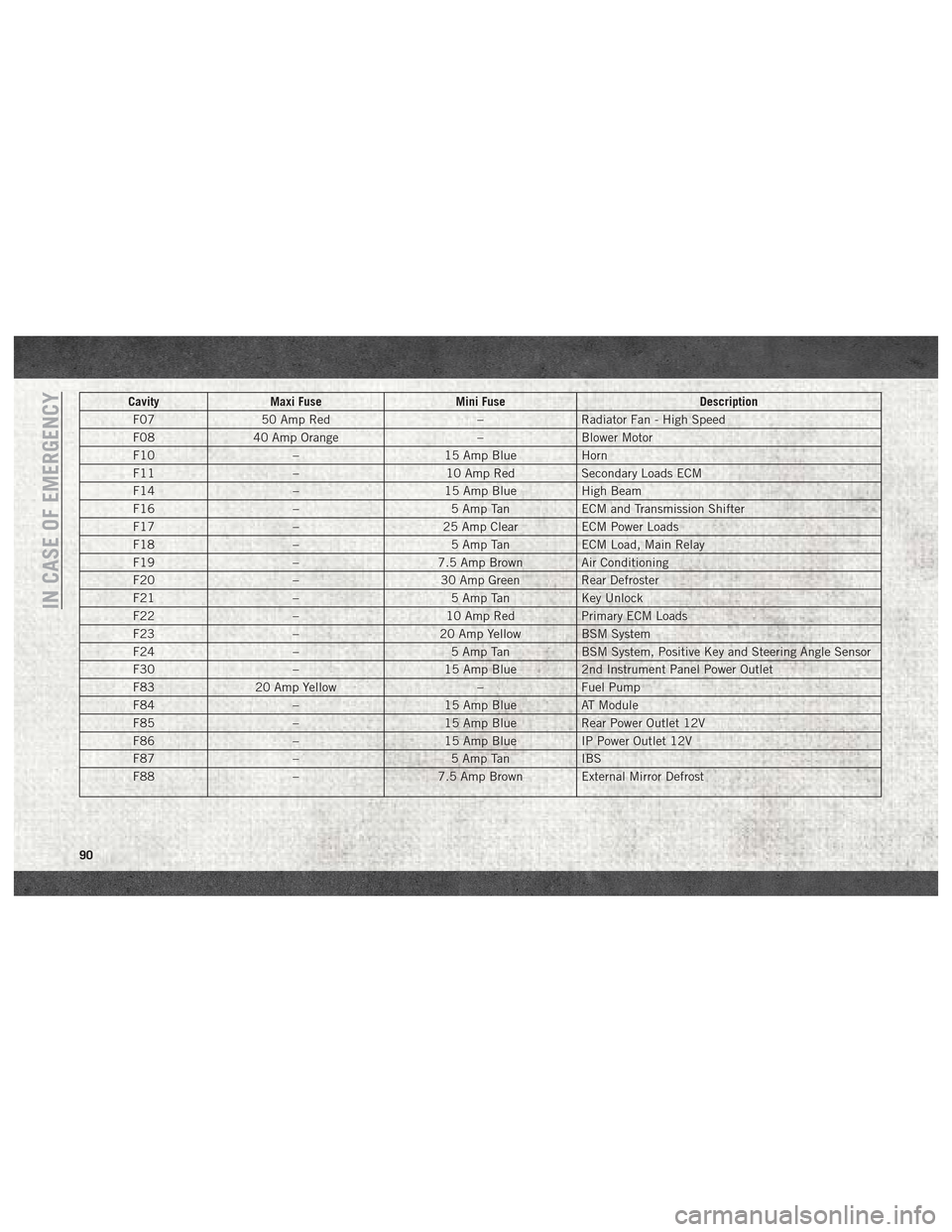
CavityMaxi Fuse Mini Fuse Description
F07 50 Amp Red –Radiator Fan - High Speed
F08 40 Amp Orange –Blower Motor
F10 –15 Amp BlueHorn
F11 –10 Amp RedSecondary Loads ECM
F14 –15 Amp BlueHigh Beam
F16 –5 Amp TanECM and Transmission Shifter
F17 –25 Amp ClearECM Power Loads
F18 –5 Amp TanECM Load, Main Relay
F19 –7.5 Amp Brown Air Conditioning
F20 –30 Amp Green Rear Defroster
F21 –5 Amp TanKey Unlock
F22 –10 Amp RedPrimary ECM Loads
F23 –20 Amp Yellow BSM System
F24 –5 Amp TanBSM System, Positive Key and Steering Angle Sensor
F30 –15 Amp Blue2nd Instrument Panel Power Outlet
F83 20 Amp Yellow –Fuel Pump
F84 –15 Amp BlueAT Module
F85 –15 Amp BlueRear Power Outlet 12V
F86 –15 Amp BlueIP Power Outlet 12V
F87 –5 Amp TanIBS
F88 –7.5 Amp Brown External Mirror Defrost
IN CASE OF EMERGENCY
90
Page 106 of 180
2. Connect the opposite end of the positive(+) jumper cable to the positive (+)post of
the booster battery.
3. Connect the negative (-)end of the jumper
cable to the negative (-)post of the
booster battery.
4. Connect the opposite end of the negative (-)jumper cable to a good engine ground
(exposed metal part of the discharged
vehicle’s engine) away from the battery
and the fuel injection system.
WARNING!
Do not connect the jumper cable to the
negative (-) post of the discharged battery.
The resulting electrical spark could cause
the battery to explode and could result in
personal injury. Only use the specific
ground point, do not use any other exposed
metal parts.
5. Start the engine in the vehicle that has the booster battery, let the engine idle a
few minutes, and then start the engine in
the vehicle with the discharged battery. 6. Once the engine is started, remove the
jumper cables in the reverse sequence:
Disconnecting The Jumper Cables
1. Disconnect the negative (-)end of the
jumper cable from the engine ground of
the vehicle with the discharged battery.
2. Disconnect the opposite end of the nega- tive (-)jumper cable from the negative (-)
post of the booster battery.
3. Disconnect the positive (+)end of the
jumper cable from the positive (+)post of
the booster battery.
4. Disconnect the opposite end of the posi- tive (+)jumper cable from the positive (+)
post of the vehicle with the discharged
battery.
If frequent jump-starting is required to start
your vehicle you should have the battery and
charging system inspected at an authorized
dealer.
CAUTION!
Accessories plugged into the vehicle
power outlets draw power from the vehi-
cle’s battery, even when not in use (i.e.,
cellular devices, etc.). Eventually, if
plugged in long enough without engine
operation, the vehicle’s battery will dis-
charge sufficiently to degrade battery life
and/or prevent the engine from starting.
IGNITION KEY REMOVAL OVERRIDE
This vehicle is equipped with a Key Ignition
Park Interlock which requires the transmis-
sion to be in PARK before the ignition switch
can be turned to the LOCK/OFF (key removal)
position. To remove the key manually, pro-
ceed as follows:
1. Firmly apply the parking brake.
2. Remove the Allen Key located in the rear cargo area, in the tool bag (if equipped) or
on the left side in the cargo box.
3. Unlock the steering column, pull the tilt/ telescoping control handle down.IN CASE OF EMERGENCY
104
Page 107 of 180
4. Pull the steering wheel outward until it isin the end of the travel position, then lock
the steering column in position, push the
control handle up until fully engaged.
5. Using the Allen Key, undo the lower steer- ing column cover screws, and remove the
lower cover.
6. Pull the release tab downwards using one hand and with the other one remove the
key, sliding it outwards.
7. Once the key is removed, reinstall the steering column cover.
CAUTION!
It is advisable to contact your authorized
dealer to have the reinstall procedure car-
ried out. If you would like to proceed in
performing the reinstall procedure special
attention must be paid to the correct cou-
pling of the clips. Otherwise damage to the
cover or noise might be heard due to incor-
rect fastening of the lower cover.
GEAR SELECTOR OVERRIDE
If a malfunction occurs and the gear selector
cannot be moved out of the PARK position,
you can use the following procedure to tem-
porarily move the gear selector:
1. Turn the engine OFF.
2. Firmly apply the parking brake.
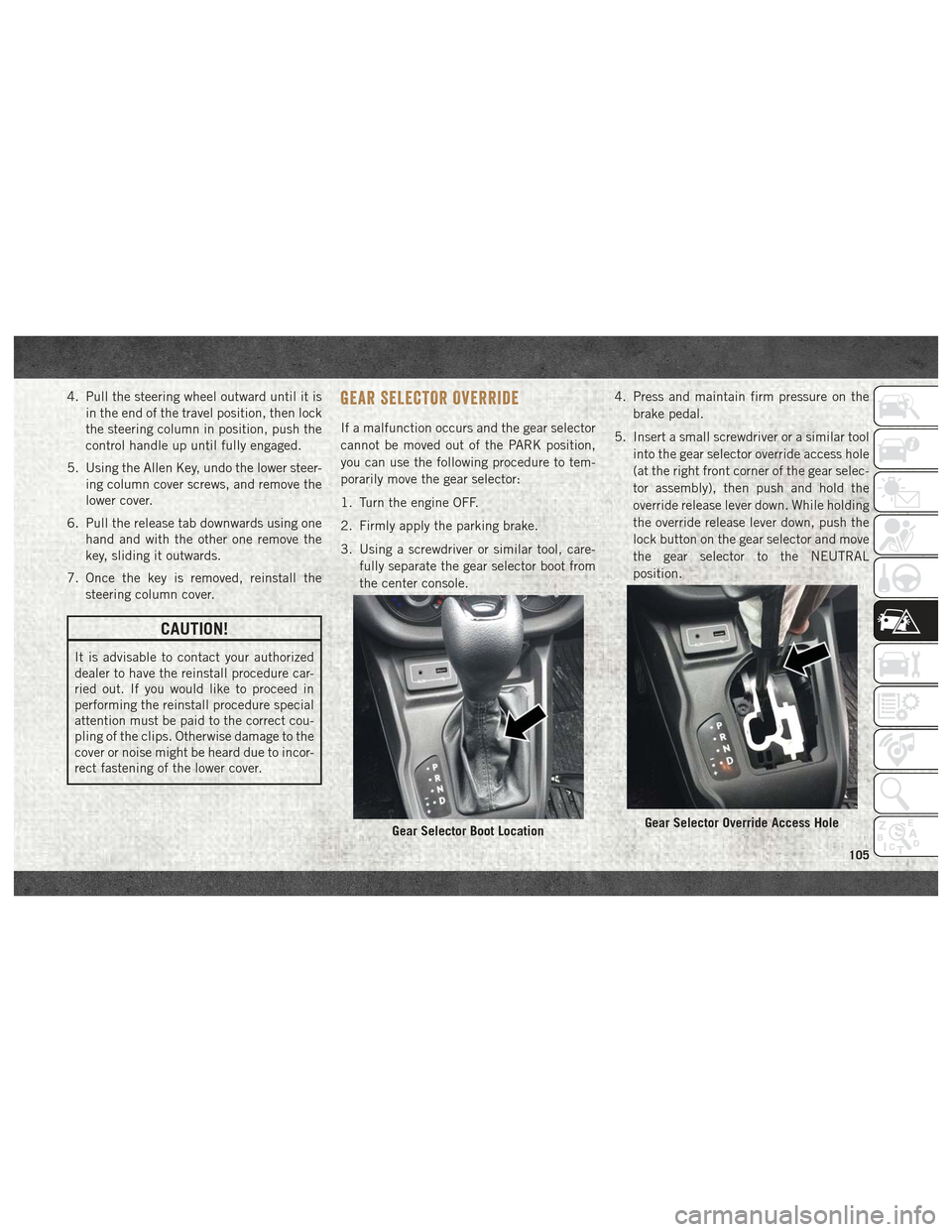
3. Using a screwdriver or similar tool, care-
fully separate the gear selector boot from
the center console. 4. Press and maintain firm pressure on the
brake pedal.
5. Insert a small screwdriver or a similar tool into the gear selector override access hole
(at the right front corner of the gear selec-
tor assembly), then push and hold the
override release lever down. While holding
the override release lever down, push the
lock button on the gear selector and move
the gear selector to the NEUTRAL
position.
Gear Selector Boot LocationGear Selector Override Access Hole
105
Page 155 of 180
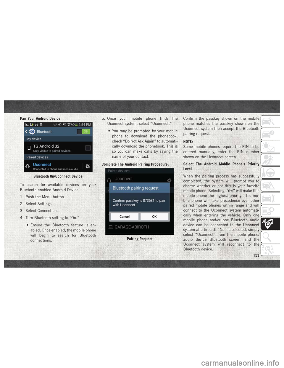
Pair Your Android Device:
To search for available devices on your
Bluetooth enabled Android Device:
1. Push the Menu button.
2. Select Settings.
3. Select Connections.
4. Turn Bluetooth setting to “On.”• Ensure the Bluetooth feature is en-abled. Once enabled, the mobile phone
will begin to search for Bluetooth
connections. 5. Once your mobile phone finds the
Uconnect system, select “Uconnect.”
• You may be prompted by your mobile phone to download the phonebook,
check “Do Not Ask Again” to automati-
cally download the phonebook. This is
so you can make calls by saying the
name of your contact.
Complete The Android Pairing Procedure: Confirm the passkey shown on the mobile
phone matches the passkey shown on the
Uconnect system then accept the Bluetooth
pairing request.
NOTE:
Some mobile phones require the PIN to be
entered manually, enter the PIN number
shown on the Uconnect screen.
Select The Android Mobile Phone's Priority
Level
When the pairing process has successfully
completed, the system will prompt you to
choose whether or not this is your favorite
mobile phone. Selecting “Yes” will make this
mobile phone the highest priority. This mo-
bile phone will take precedence over other
paired mobile phones within range and will
connect to the Uconnect system automati-
cally when entering the vehicle. Only one
mobile phone and/or one Bluetooth audio
device can be connected to the Uconnect
system at a time. If “No” is selected, simply
select “Uconnect” from the mobile phone/
audio device Bluetooth screen, and the
Uconnect system will reconnect to the
Bluetooth device.
Bluetooth On/Uconnect Device
Pairing Request
153
Page 160 of 180
ments, such as aboard airplanes. If you are
unsure of restrictions, you are encouraged to
ask for authorization before turning on the
wireless radio.
This device complies with Part 15 of the FCC
Rules and with Industry Canada license-
exempt RSS standard(s). Operation is sub-
ject to the following two conditions:
1. This device may not cause harmfulinterference.
2. This device must accept any interference received, including interference that may
cause undesired operation.
NOTE:
Changes or modifications not expressly ap-
proved by the party responsible for compli-
ance could void the user’s authority to oper-
ate the equipment. NOTE:
• This equipment has been tested and found
to comply with the limits for a Class B
digital device, pursuant to Part 15 of the
FCC Rules. These limits are designed to
provide reasonable protection against
harmful interference in a residential instal-
lation. This equipment generates, uses and
can radiate radio frequency energy and, if
not installed and used in accordance with
the instructions, may cause harmful inter-
ference to radio communications. However,
there is no guarantee that interference will
not occur in a particular installation.
• If this equipment does cause harmful inter- ference to radio or television reception,
which can be determined by turning the
equipment off and on, the user is encour-
aged to try to correct the interference by
one or more of the following measures:
1. Increase the separation between the equipment and receiver.
2. Consult the dealer or an experienced radio technician for help.UCONNECT VOICE RECOGNITION
QUICK TIPS
Introducing Uconnect
Start using Uconnect Voice Recognition with
these helpful quick tips. It provides the key
Voice Commands and tips you need to know
to control your Uconnect system.
Key Features:
• Five-inch Color Touchscreen Display withAM/FM/USB/Bluetooth
• Bluetooth with integrated voice control
• GPS navigation (if equipped)
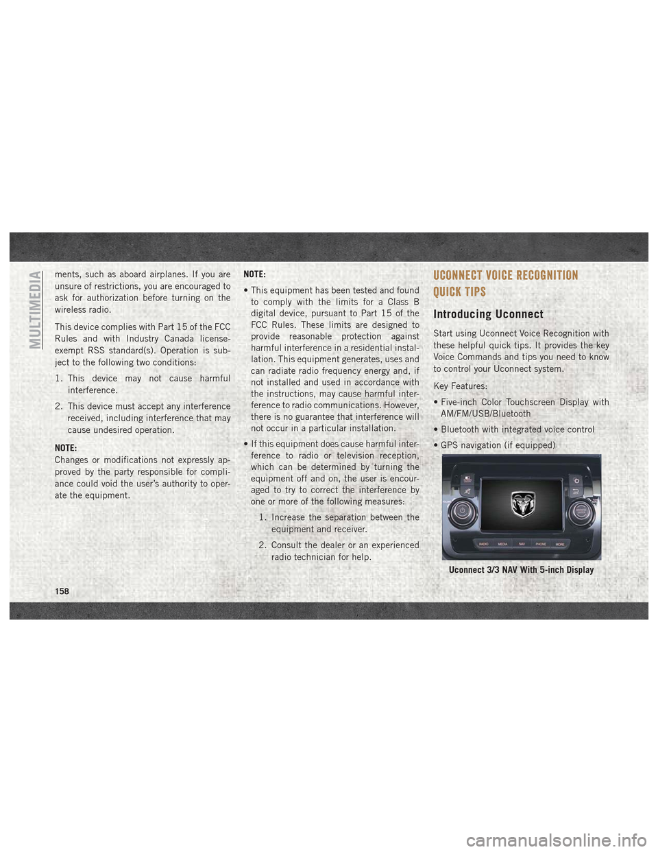
Uconnect 3/3 NAV With 5-inch Display
MULTIMEDIA
158