key Ram ProMaster City 2018 User Guide
[x] Cancel search | Manufacturer: RAM, Model Year: 2018, Model line: ProMaster City, Model: Ram ProMaster City 2018Pages: 180, PDF Size: 7.52 MB
Page 1 of 180

18VM-926-AA
RAM ProMaster CITYFirst EditionUser GUIDE
RAMTRUCKS.COM (U.S.) ramtrucks.ca (CANADA)
©2017 FCA US LLC. All Rights Reserved. RAM is a registered trademark of FCA US LLC.
DOWNLOAD A FREE ELECTRONIC COPY OF
THE MOST UP-TO-DATE OWNER’S MANUAL, MEDIA
AND WARRANTY BOOKLET BY VISITING:
WWW.MOPAR.COM/EN-US/CARE/OWNERS-MANUAL.HTML (U.S. RESIDENts); WWW.OWNERS.MOPAR.CA (CANADIAN RESIDENts).
WHETHER IT’S PROVIDING INFORMATION
ABOUT SPECIFIC PRODUCT FEATURES,
TAKING A TOUR THROUGH YOUR VEHICLE’S HERITAGE, KNOWING WHAT STEPS TO
TAKE FOLLOWING AN ACCIDENT, OR SCHEDULING YOUR NEXT APPOINTMENT, WE KNOW YOU’LL FIND THE APP AN IMPORTANT EXTENSION OF YOUR RAM VEHICLE. SIMPLY
DOWNLOAD THE APP, SELECT YOUR MAKE AND MODEL
AND ENJOY THE RIDE. TO GET THIS APP, GO DIRECTLY TO
THE APP STORE OR GOOGLE PLAY AND ENTER THE SEARCH KEYWORD “RAM TOOLBOX” (U.S. residents ONLY).
WWW.RAMTRUCKS.COM/EN/OWNERS (U.S.) or
WWW.OWNERS.MOPAR.CA (CANADA) PROVIDES SPECIAL OFFERS TAILORED TO YOUR NEEDS, CUSTOMIZED VEHICLE GALLERIES, PERSONALIZED SERVICE RECORDS AND MORE.
TO GET THIS INFORMATION, JUST CREATE AN ACCOUNT AND CHECK BACK OFTEN.
Get warranty and other information online – you
can review and print or download a copy of the
owner’s manual, navigation/uconnect manuals
and the limited warranties provided by FCA US LLC for your vehicle by visiting www.mopar.com (U.S.)
or WWW.OWNERS.MOPAR.CA (CANADA). Click on the
applicable link in the “popular topics” area of the
www.mopar.com (U.S.) or WWW.OWNERS.MOPAR.CA (CANADA) homepage and follow the instructions
to select the applicable year, make and model of your vehicle.
2018
RAM
PROMASTER CITY
USER
GUIDE
Page 4 of 180
HOW TO USE THIS MANUAL
Essential Information
Each time direction instructions (left/right or
forwards/backwards) about the vehicle are
given, these must be intended as regarding
an occupant in the driver's seat. Special
cases not complying with this rule will be
properly specified in the text.
The figures in this User Guide are provided by
way of example only: this might imply that
some details of the image do not correspond
to the actual arrangement of your vehicle.
In addition, the User Guide has been con-
ceived considering vehicles with steering
wheel on the left side; it is therefore possiblethat on vehicles with steering wheel on the
right side, the position or construction of
some controls is not exactly mirror-like with
respect to the figure.
To identify the chapter with the information
needed you can consult the index at the end
of this User Guide.
Chapters can be rapidly identified with dedi-
cated graphic tabs, at the side of each odd
page. A few pages further there is a key for
getting to know the chapter order and the
relevant symbols in the tabs. There is anyway
a textual indication of the current chapter at
the side of each even page.
Symbols
Some vehicle components have colored la-
bels whose symbols indicate precautions to
be observed when using this component.
WARNINGS AND CAUTIONS
While reading this User Guide you will find a
series of WARNINGS to be followed to pre-
vent incorrect use of components which
could cause accidents or injuries.
There are also CAUTIONS that must be fol-
lowed to prevent against procedures that
could result in damage to your vehicle.INTRODUCTION
2
Page 11 of 180
GETTING TO KNOW YOUR VEHICLE
KEYS......................10
KeyFob.....................10
SEATS .....................11
Heated Seats — If Equipped ........11
Folding Rear Seat — If Equipped .....12
HEAD RESTRAINTS..............13
Front Adjustment...............14
Rear Adjustment ...............14
Front Removal .................15
Rear Removal .................15
STEERING WHEEL ..............16
Tilt/Telescoping Steering Column .....16
EXTERIOR LIGHTS..............16
Multifunction Lever ..............16
Headlights ...................17
High Beams ..................17
Parking Lights .................17
Follow Me Home/Headlight Delay .....17
Turn Signals ..................17
Lane Change Assist .............17
INTERIOR LIGHTS...............18
WIPERS AND WASHERS ..........18
Front Wiper Operation............18
Rear Wiper Operation .............19
CLIMATE CONTROLS.............20
Manual Climate Control Overview .....20
Climate Control Functions ..........23
Operating Tips .................24
HOOD......................25
Opening .....................25
Closing .....................25
INTERNAL EQUIPMENT ...........26
Power Outlets.................26
Cigar Lighter And Ash Receiver — If
Equipped ...................27
GETTING TO KNOW YOUR VEHICLE
9
Page 12 of 180
KEYS
Key Fob
Your vehicle uses a key start ignition system.
The ignition system consists of a key fob with
a Remote Keyless Entry (RKE) and an igni-
tion switch.
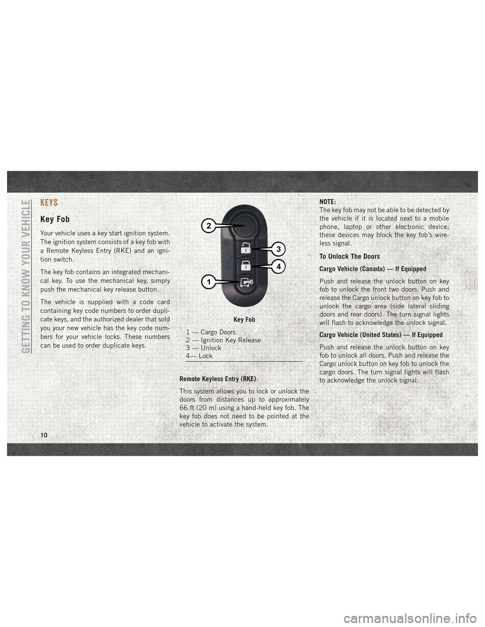
The key fob contains an integrated mechani-
cal key. To use the mechanical key, simply
push the mechanical key release button.
The vehicle is supplied with a code card
containing key code numbers to order dupli-
cate keys, and the authorized dealer that sold
you your new vehicle has the key code num-
bers for your vehicle locks. These numbers
can be used to order duplicate keys.Remote Keyless Entry (RKE)
This system allows you to lock or unlock the
doors from distances up to approximately
66 ft (20 m) using a hand-held key fob. The
key fob does not need to be pointed at the
vehicle to activate the system. NOTE:
The key fob may not be able to be detected by
the vehicle if it is located next to a mobile
phone, laptop or other electronic device;
these devices may block the key fob’s wire-
less signal.
To Unlock The Doors
Cargo Vehicle (Canada) — If Equipped
Push and release the unlock button on key
fob to unlock the front two doors. Push and
release the Cargo unlock button on key fob to
unlock the cargo area (side lateral sliding
doors and rear doors). The turn signal lights
will flash to acknowledge the unlock signal.
Cargo Vehicle (United States) — If Equipped
Push and release the unlock button on key
fob to unlock all doors. Push and release the
Cargo unlock button on key fob to unlock the
cargo doors. The turn signal lights will flash
to acknowledge the unlock signal.
Key Fob
1 — Cargo Doors
2 — Ignition Key Release
3 — Unlock
4— Lock
GETTING TO KNOW YOUR VEHICLE
10
Page 13 of 180
Passenger Vehicle
Push and release the unlock button on key
fob to unlock all doors. Push and release the
Cargo unlock button on key fob to unlock the
cargo doors. The turn signal lights will flash
to acknowledge the unlock signal.
To Lock The Doors
Push and release the lock button on the key
fob to lock all doors. The turn signal lights
will flash to acknowledge the signal; the horn
will chirp too during turn signal lights flash-
ing.
If a door is open, the turn signal lights will
flash at an increased rate, and there will be
no horn chirp. This is to indicate that a door is
still open.
Locking Doors With A Key
1. Insert the key with either side up.
2. Turn the key to the right to lock the door.
3. Turn the key to the left to unlock the door.For maintenance procedures, refer to
“Dealer Service” in “Servicing And Mainte-
nance” in the Owner’s Manual at
www.mopar.com/en-us/care/owners-manual.html
(U.S. Residents) or www.owners.mopar.ca
(Canadian Residents).
General Information
The following regulatory statement applies to
all radio frequency (RF) devices equipped in
this vehicle:
This device complies with Part 15 of the FCC
Rules and with Industry Canada license-
exempt RSS standard(s). Operation is sub-
ject to the following two conditions:
1. This device may not cause harmful inter-
ference, and
2. This device must accept any interference received, including interference that may
cause undesired operation.
NOTE:
Changes or modifications not expressly ap-
proved by the party responsible for compli-
ance could void the user’s authority to oper-
ate the equipment.
SEATS
Seats are a part of the Occupant Restraint
System of the vehicle.
WARNING!
• It is dangerous to ride in a cargo area, inside or outside of a vehicle. In a colli-
sion, people riding in these areas are
more likely to be seriously injured or
killed.
• Do not allow people to ride in any area of
your vehicle that is not equipped with
seats and seat belts. In a collision,
people riding in these areas are more
likely to be seriously injured or killed.
• Be sure everyone in your vehicle is in a
seat and using a seat belt properly.
Heated Seats — If Equipped
On some models, the front driver and passen-
ger seats may be equipped with heaters in
both the seat cushions and seatbacks. The
controls for the front heated seats are located
on the lower outboard side of the seat.
11
Page 14 of 180
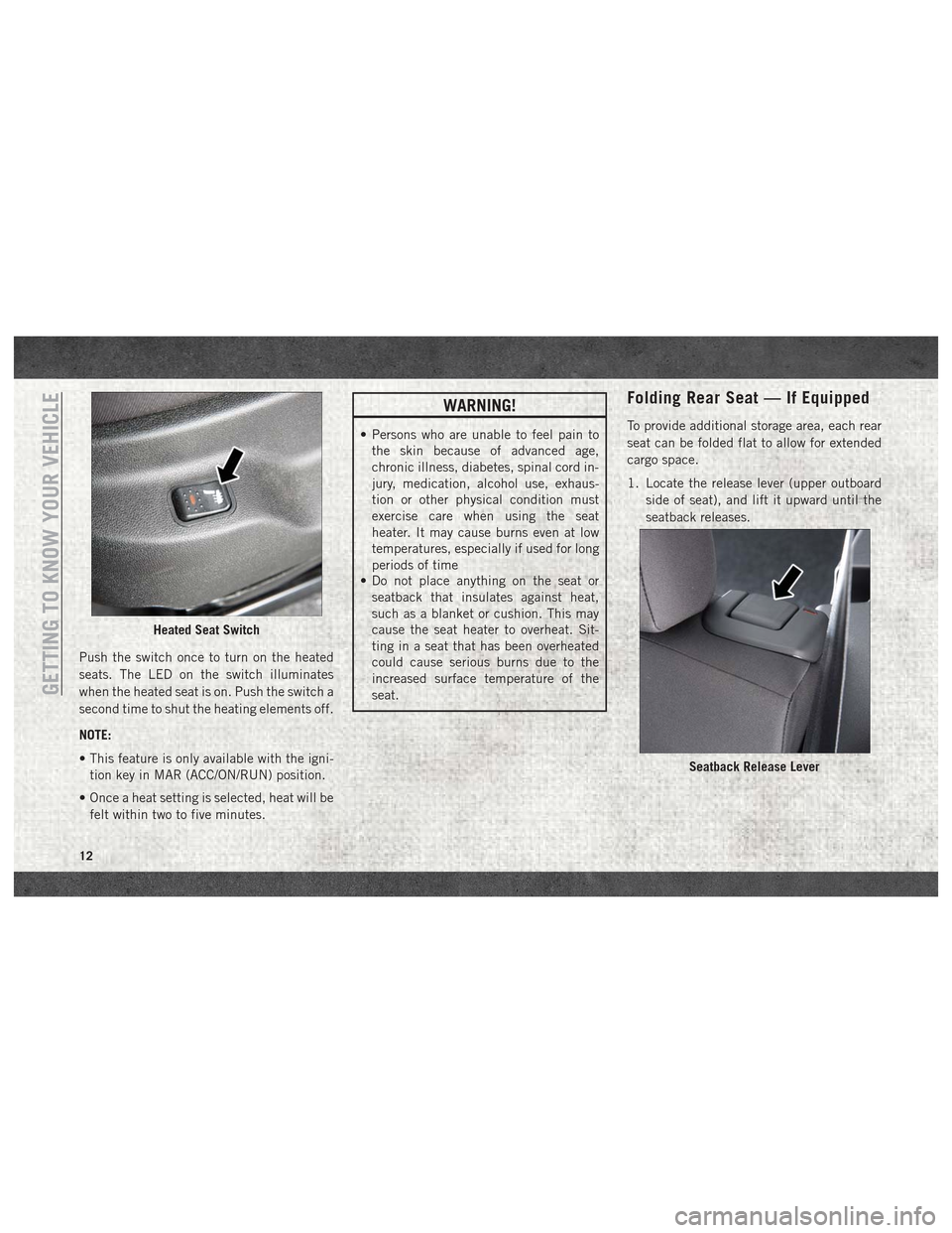
Push the switch once to turn on the heated
seats. The LED on the switch illuminates
when the heated seat is on. Push the switch a
second time to shut the heating elements off.
NOTE:
• This feature is only available with the igni-tion key in MAR (ACC/ON/RUN) position.
• Once a heat setting is selected, heat will be felt within two to five minutes.
WARNING!
• Persons who are unable to feel pain to the skin because of advanced age,
chronic illness, diabetes, spinal cord in-
jury, medication, alcohol use, exhaus-
tion or other physical condition must
exercise care when using the seat
heater. It may cause burns even at low
temperatures, especially if used for long
periods of time
• Do not place anything on the seat or
seatback that insulates against heat,
such as a blanket or cushion. This may
cause the seat heater to overheat. Sit-
ting in a seat that has been overheated
could cause serious burns due to the
increased surface temperature of the
seat.
Folding Rear Seat — If Equipped
To provide additional storage area, each rear
seat can be folded flat to allow for extended
cargo space.
1. Locate the release lever (upper outboard
side of seat), and lift it upward until the
seatback releases.
Heated Seat Switch
Seatback Release Lever
GETTING TO KNOW YOUR VEHICLE
12
Page 19 of 180
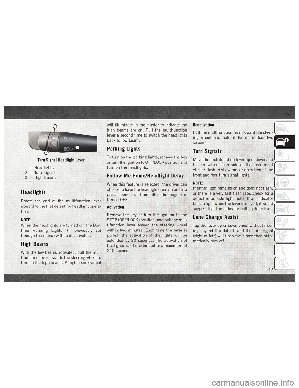
Headlights
Rotate the end of the multifunction lever
upward to the first detent for headlight opera-
tion.
NOTE:
When the headlights are turned on, the Day-
time Running Lights, (if previously set
through the menu) will be deactivated.
High Beams
With the low beams activated, pull the mul-
tifunction lever towards the steering wheel to
turn on the high beams. A high beam symbolwill illuminate in the cluster to indicate the
high beams are on. Pull the multifunction
lever a second time to switch the headlights
back to low beam.
Parking Lights
To turn on the parking lights, remove the key
or turn the ignition to OFF/LOCK position and
turn on the headlights.
Follow Me Home/Headlight Delay
When this feature is selected, the driver can
choose to have the headlights remain on for a
preset period of time after the engine is
turned OFF.
Activation
Remove the key or turn the ignition to the
STOP (OFF/LOCK) position, and pull the mul-
tifunction lever toward the steering wheel
within two minutes. Each time the lever is
pulled, the activation of the lights will be
extended by 30 seconds. The activation of
the lights can be extended to a maximum of
210 seconds.
Deactivation
Pull the multifunction lever toward the steer-
ing wheel and hold it for more than two
seconds.
Turn Signals
Move the multifunction lever up or down and
the arrows on each side of the instrument
cluster flash to show proper operation of the
front and rear turn signal lights.
NOTE:
If either light remains on and does not flash,
or there is a very fast flash rate, check for a
defective outside light bulb. If an indicator
fails to light when the lever is moved, it would
suggest that the indicator bulb is defective.
Lane Change Assist
Tap the lever up or down once, without mov-
ing beyond the detent, and the turn signal
(right or left) will flash five times then auto-
matically turn off.
Turn Signal Headlight Lever
1 — Headlights
2 — Turn Signals
3 — High Beams
17
Page 28 of 180
INTERNAL EQUIPMENT
Power Outlets
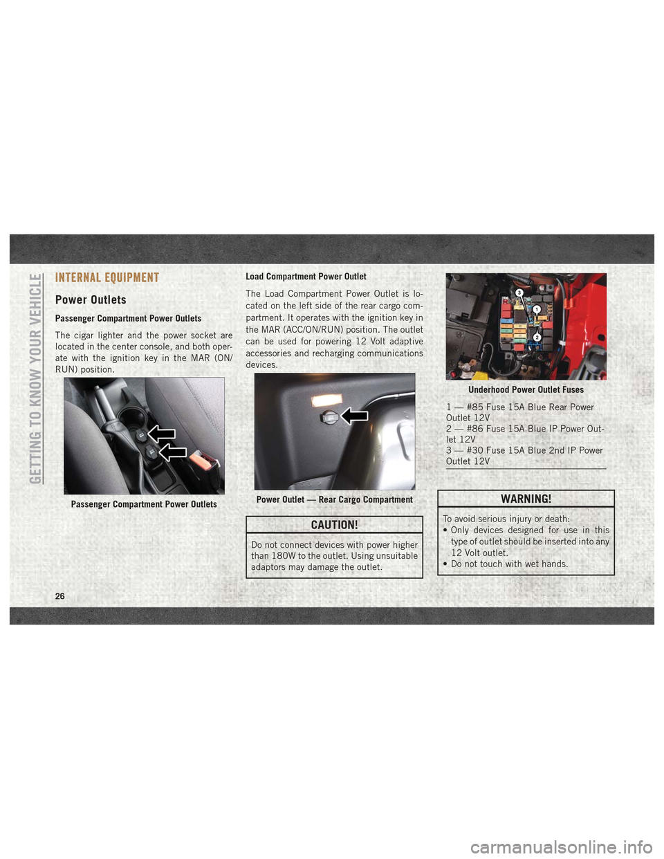
Passenger Compartment Power Outlets
The cigar lighter and the power socket are
located in the center console, and both oper-
ate with the ignition key in the MAR (ON/
RUN) position.Load Compartment Power Outlet
The Load Compartment Power Outlet is lo-
cated on the left side of the rear cargo com-
partment. It operates with the ignition key in
the MAR (ACC/ON/RUN) position. The outlet
can be used for powering 12 Volt adaptive
accessories and recharging communications
devices.
CAUTION!
Do not connect devices with power higher
than 180W to the outlet. Using unsuitable
adaptors may damage the outlet.
WARNING!
To avoid serious injury or death:
• Only devices designed for use in this
type of outlet should be inserted into any
12 Volt outlet.
• Do not touch with wet hands.
Passenger Compartment Power OutletsPower Outlet — Rear Cargo Compartment
Underhood Power Outlet Fuses
1 — #85 Fuse 15A Blue Rear Power
Outlet 12V
2 — #86 Fuse 15A Blue IP Power Out-
let 12V
3 — #30 Fuse 15A Blue 2nd IP Power
Outlet 12V
GETTING TO KNOW YOUR VEHICLE
26
Page 29 of 180
WARNING!
• Close the lid when not in use and whiledriving the vehicle.
• If this outlet is mishandled, it may cause
an electric shock and failure.
CAUTION!
• Many accessories that can be plugged indraw power from the vehicle's battery,
even when not in use (i.e., cellular
phones, etc.). Eventually, if plugged in
long enough, the vehicle's battery will
discharge sufficiently to degrade battery
life and/or prevent the engine from start-
ing.
• Accessories that draw higher power (i.e.,
coolers, vacuum cleaners, lights, etc.)
CAUTION!
will degrade the battery even more
quickly. Only use these intermittently
and with greater caution.
• After the use of high power draw acces-
sories, or long periods of the vehicle not
being started (with accessories still
plugged in), the vehicle must be driven a
sufficient length of time to allow the
generator to recharge the vehicle's bat-
tery.
Cigar Lighter And Ash Receiver —
If Equipped
A removable ash receiver and cigar lighter are
available. Push the cigar lighter button to activate the
cigar lighter when the ignition key is in the
MAR (ON/RUN) position.
After a few seconds the button returns to its
initial position and the cigar lighter is ready
for use.
NOTE:
Always check that the cigar lighter has turned
itself off.
WARNING!
The cigar lighter becomes very hot. Handle
it carefully and make sure children don’t
touch it: risk of fire and/or burning.
27
Page 38 of 180
CAUTION!
The TPMS has been optimized for the
original equipment tires and wheels.
TPMS pressures and warning have been
established for the tire size equipped on
your vehicle. Undesirable system opera-
tion or sensor damage may result when
using replacement equipment that is not
of the same size, type, and/or style. After-
market wheels can cause sensor damage.
Using aftermarket tire sealants may cause
the Tire Pressure Monitoring System
(TPMS) sensor to become inoperable. Af-
ter using an aftermarket tire sealant it is
recommended that you take your vehicle
to your authorized dealer to have your
sensor function checked.
— Vehicle Security Warning Light
This telltale will illuminate when the vehicle
security alarm system has detected an at-
tempt was made to break into the vehicle.
— Engine Check/Malfunction Indica-
tor Warning Light (MIL)
The Engine Check/Malfunction Indicator
Light (MIL) is a part of an Onboard Diagnostic
System called OBD II that monitors engine
and automatic transmission control systems.
The light will illuminate when the ignition is
in the ON/RUN position before engine start.
If the bulb does not come on when turning
the key from OFF to ON/RUN, have the con-
dition checked promptly.
Certain conditions, such as a loose or missing
gas cap, poor quality fuel, etc., may illumi-
nate the light after engine start. The vehicle
should be serviced if the light stays on
through several typical driving styles. In most
situations, the vehicle will drive normally and
will not require towing.
When the engine is running, the MIL may
flash to alert serious conditions that could
lead to immediate loss of power or severe
catalytic converter damage. The vehicle
should be serviced as soon as possible if this
occurs.
WARNING!
A malfunctioning catalytic converter, as
referenced above, can reach higher tem-
peratures than in normal operating condi-
tions. This can cause a fire if you drive
slowly or park over flammable substances
such as dry plants, wood, cardboard, etc.
This could result in death or serious injury
to the driver, occupants or others.
CAUTION!
Prolonged driving with the Malfunction
Indicator Light (MIL) on could cause dam-
age to the vehicle control system. It also
could affect fuel economy and driveability.
If the MIL is flashing, severe catalytic
converter damage and power loss will soon
occur. Immediate service is required.
GETTING TO KNOW YOUR INSTRUMENT PANEL
36