tow Ram ProMaster City 2018 Owner's Manual
[x] Cancel search | Manufacturer: RAM, Model Year: 2018, Model line: ProMaster City, Model: Ram ProMaster City 2018Pages: 180, PDF Size: 7.52 MB
Page 81 of 180
STARTING AND OPERATING
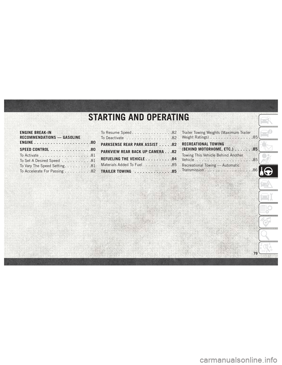
ENGINE BREAK-IN
RECOMMENDATIONS — GASOLINE
ENGINE.....................80
SPEED CONTROL ...............80
To Activate...................81
To Set A Desired Speed ...........81
To Vary The Speed Setting ..........81
To Accelerate For Passing ..........82To Resume Speed
...............82
To Deactivate .................82
PARKSENSE REAR PARK ASSIST .....82
PARKVIEW REAR BACK UP CAMERA . . .82
REFUELING THE VEHICLE ..........84
Materials Added To Fuel ..........85
TRAILER TOWING..............85
Trailer Towing Weights (Maximum Trailer
Weight Ratings)................85
RECREATIONAL TOWING
(BEHIND MOTORHOME, ETC.) .......85
Towing This Vehicle Behind Another
Vehicle.....................85
Recreational Towing — Automatic
Transmission ..................86
STARTING AND OPERATING
79
Page 87 of 180
Materials Added To Fuel
Designated TOP TIER
Detergent Gasoline
contains a higher level
of detergents to further
aide in minimizing en-
gine and fuel system
deposits. When avail-
able, the usage of Top
Tier Detergent gasoline is recommended.
Visit www.toptiergas.com for a list of TOP
TIER Detergent Gasoline Retailers. Indiscriminate use of fuel system cleaning
agents should be avoided. Many of these
materials intended for gum and varnish re-
moval may contain active solvents or similar
ingredients. These can harm fuel system gas-
ket and diaphragm materials.
TRAILER TOWING
Trailer Towing Weights (Maximum
Trailer Weight Ratings)
NOTE:
For trailer towing information (maximum
trailer weight ratings) refer to the following
website addresses:
•
ramtrucks.com/en/towing_guide/
• ramtruck.ca (Canada)
• rambodybuilder.com
RECREATIONAL TOWING (BEHIND MOTORHOME, ETC.)
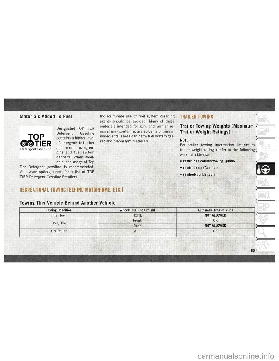
Towing This Vehicle Behind Another Vehicle
Towing Condition Wheels OFF The Ground Automatic Transmission
Flat Tow NONENOT ALLOWED
Dolly Tow Front
OK
Rear NOT ALLOWED
On Trailer ALLOK
85
Page 88 of 180
NOTE:
When towing your vehicle, always follow ap-
plicable state and provincial laws. Contact
state and provincial Highway Safety offices
for additional details.
Recreational Towing — Automatic
Transmission
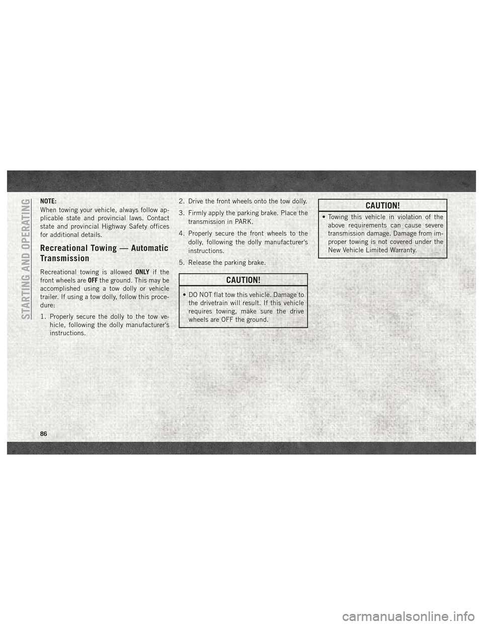
Recreational towing is allowedONLYif the
front wheels are OFFthe ground. This may be
accomplished using a tow dolly or vehicle
trailer. If using a tow dolly, follow this proce-
dure:
1. Properly secure the dolly to the tow ve- hicle, following the dolly manufacturer's
instructions. 2. Drive the front wheels onto the tow dolly.
3. Firmly apply the parking brake. Place the
transmission in PARK.
4. Properly secure the front wheels to the dolly, following the dolly manufacturer's
instructions.
5. Release the parking brake.
CAUTION!
• DO NOT flat tow this vehicle. Damage to the drivetrain will result. If this vehicle
requires towing, make sure the drive
wheels are OFF the ground.
CAUTION!
• Towing this vehicle in violation of theabove requirements can cause severe
transmission damage. Damage from im-
proper towing is not covered under the
New Vehicle Limited Warranty.
STARTING AND OPERATING
86
Page 89 of 180
IN CASE OF EMERGENCY
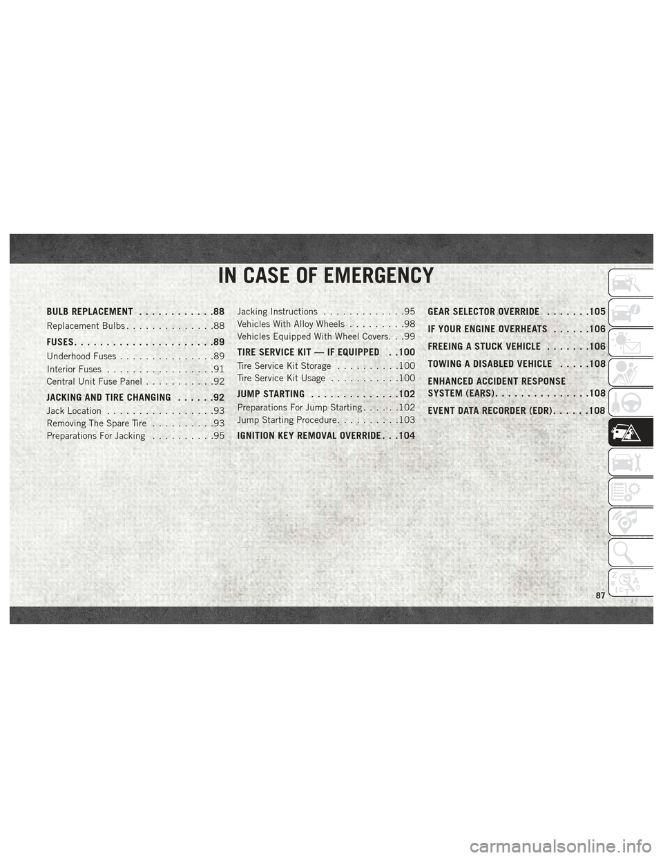
BULB REPLACEMENT............88
Replacement Bulbs..............88
FUSES......................89
Underhood Fuses ...............89
Interior Fuses .................91
Central Unit Fuse Panel ...........92
JACKING AND TIRE CHANGING ......92
Jack Location.................93
Removing The Spare Tire ..........93
Preparations For Jacking ..........95Jacking Instructions
.............95
Vehicles With Alloy Wheels .........98
Vehicles Equipped With Wheel Covers. . .99
TIRE SERVICE KIT — IF EQUIPPED . .100
Tire Service Kit Storage ..........100
Tire Service Kit Usage ...........100
JUMP STARTING..............102
Preparations For Jump Starting ......102
Jump Starting Procedure ..........103
IGNITION KEY REMOVAL OVERRIDE . . .104 GEAR SELECTOR OVERRIDE
.......105
IF YOUR ENGINE OVERHEATS ......106
FREEING A STUCK VEHICLE .......106
TOWING A DISABLED VEHICLE .....108
ENHANCED ACCIDENT RESPONSE
SYSTEM (EARS) ...............108
EVENT DATA RECORDER (EDR) ......108
IN CASE OF EMERGENCY
87
Page 95 of 180

Jack Location
The jack and tools are stowed under the
driver’s front seat.
Removing The Spare Tire
1. Remove the spare tire before attemptingto jack up the vehicle. Attach the wrench
handle to the winch extension. 2. To access the winch mechanism open the
rear doors of the vehicle to expose the winch mechanism access cover. Remove
the access cover and install the winch
extension into the winch mechanism.
Jack/Tools Location
Jack Tools
1 — Wrench Handle
2 — Winch Extension
3 — Emergency Screwdriver
4 — Bolt Install Wrench
5 — Wheel Chock
6 — Jack
Jack Tools
1 — Wrench Handle
2 — Winch Extension
93
Page 96 of 180
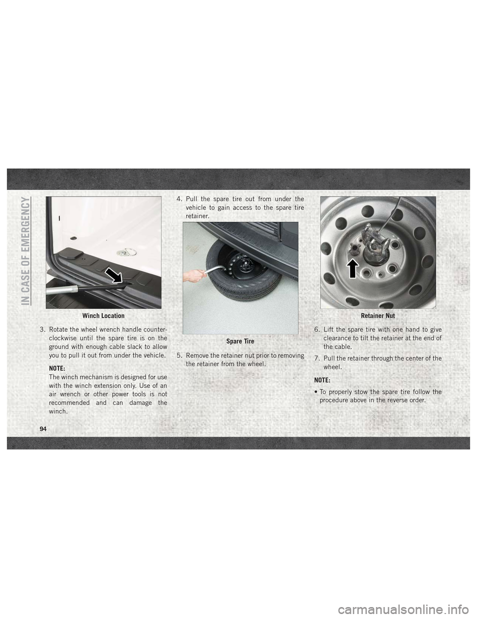
3. Rotate the wheel wrench handle counter-clockwise until the spare tire is on the
ground with enough cable slack to allow
you to pull it out from under the vehicle.
NOTE:
The winch mechanism is designed for use
with the winch extension only. Use of an
air wrench or other power tools is not
recommended and can damage the
winch. 4. Pull the spare tire out from under the
vehicle to gain access to the spare tire
retainer.
5. Remove the retainer nut prior to removing the retainer from the wheel. 6. Lift the spare tire with one hand to give
clearance to tilt the retainer at the end of
the cable.
7. Pull the retainer through the center of the wheel.
NOTE:
• To properly stow the spare tire follow the procedure above in the reverse order.
Winch Location
Spare Tire
Retainer Nut
IN CASE OF EMERGENCY
94
Page 98 of 180
WARNING!
• If working on or near a roadway, beextremely careful of motor traffic.
• To assure that spare tires, flat or in-
flated, are securely stowed, spares must
be stowed with the valve stem facing the
ground.
• The stowed spare tire should always be
checked for security by pushing on it
with your hand , at the location under
the rear bumper, behind the vehicle. The
spare tire should not move when fully
secured by the winch under the vehicle.
CAUTION!
Do not attempt to raise the vehicle by
jacking on locations other than those indi-
cated in the Jacking Instructions for this
vehicle.
1. Loosen (but do not remove) the wheel lug bolts with the wrench handle by turning
them to the left one turn while the wheel
is still on the ground. 2. There are two jack engagement locations
on each side of the vehicle body.
NOTE:
Place the jack underneath the jack engage-
ment location that is closest to the flat tire.
WARNING!
Being under a jacked-up vehicle is danger-
ous. The vehicle could slip off the jack and
fall on you. You could be crushed. Never
get any part of your body under a vehicle
that is on a jack. If you need to get under a
raised vehicle, take it to a service center
where it can be raised on a lift.
CAUTION!
Do not attempt to raise the vehicle by
jacking on locations other than those indi-
cated in the Jacking Instructions for this
vehicle.
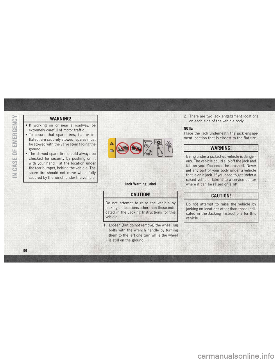
Jack Warning Label
IN CASE OF EMERGENCY
96
Page 100 of 180
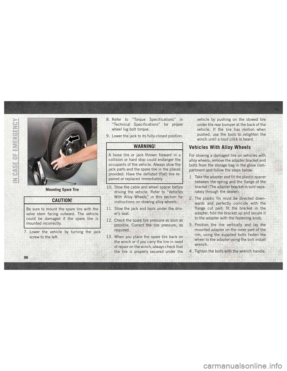
CAUTION!
Be sure to mount the spare tire with the
valve stem facing outward. The vehicle
could be damaged if the spare tire is
mounted incorrectly.
7. Lower the vehicle by turning the jack screw to the left. 8. Refer to “Torque Specifications” in
“Technical Specifications” for proper
wheel lug bolt torque.
9. Lower the jack to its fully-closed position.
WARNING!
A loose tire or jack thrown forward in a
collision or hard stop could endanger the
occupants of the vehicle. Always stow the
jack parts and the spare tire in the places
provided. Have the deflated (flat) tire re-
paired or replaced immediately.
10. Stow the cable and wheel spacer before driving the vehicle. Refer to “Vehicles
With Alloy Wheels” in this section for
instructions on stowing alloy wheels.
11. Stow the jack and tools under the driv- er’s seat.
12. Check the spare tire pressure as soon as possible. Correct the tire pressure, as
required.
13. When you place the spare tire back on the winch or if you carry the tire in need
of repair on the winch, always check that
the tire is properly secured under the vehicle by pushing on the stowed tire
under the rear bumper at the back of the
vehicle. If the tire has motion when
pushed, use the tools to retighten the
winch until a loud click is heard.
Vehicles With Alloy Wheels
For stowing a damaged tire on vehicles with
alloy wheels, remove the adapter bracket and
bolts from the storage bag in the glove com-
partment and follow the steps below:
1. Take the adapter and fit the plastic spacer
between the spring and the flange of the
bracket (The adapter bracket is sold sepa-
rately through the dealer).
2. The plastic fin must be directed down- wards and perfectly coincide with the
flange cut part; fit the bracket in the
adapter, fold the bracket up and secure it
to the adapter with the fastening knob.
3. Position the tire vertically and lay the mounted adapter on the inner part of the
rim, using the supplied bolts fasten the
wheel to the adapter using the bolt install
wrench.
4. Tighten the bolts with the wrench handle.
Mounting Spare Tire
IN CASE OF EMERGENCY
98
Page 101 of 180
5. Rotate the winch mechanism clockwiseuntil the wheel is properly stowed under
the vehicle and until the wench makes
three audible noises.
6. Reach underneath and shake tire by hand to confirm that it is secure. The tire should
not move. If the tire is still loose and/or
three audible noises are not heard, place
and secure damaged wheel into the ve-
hicle and seek dealer assistance for the
winch mechanism.
This is for temporary use only.
Vehicles Equipped With Wheel
Covers
1. Mount the road tire on the axle.
2. To ease the installation process for steel wheels with wheel covers, install two
wheel bolts on the wheel. Install the wheel
bolts with the threaded end of the bolt
toward the wheel. Lightly tighten the
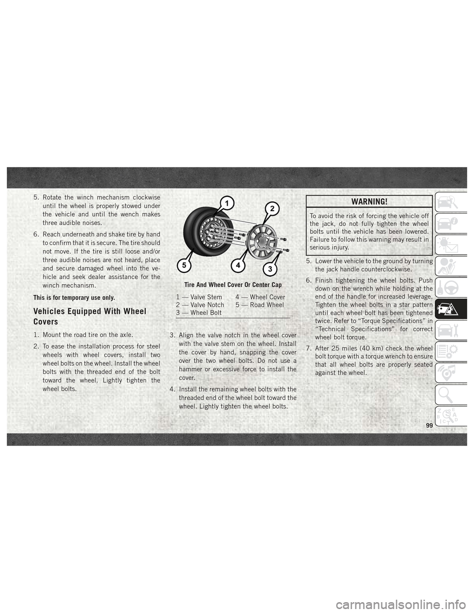
wheel bolts. 3. Align the valve notch in the wheel cover
with the valve stem on the wheel. Install
the cover by hand, snapping the cover
over the two wheel bolts. Do not use a
hammer or excessive force to install the
cover.
4. Install the remaining wheel bolts with the threaded end of the wheel bolt toward the
wheel. Lightly tighten the wheel bolts.
WARNING!
To avoid the risk of forcing the vehicle off
the jack, do not fully tighten the wheel
bolts until the vehicle has been lowered.
Failure to follow this warning may result in
serious injury.
5. Lower the vehicle to the ground by turning the jack handle counterclockwise.
6. Finish tightening the wheel bolts. Push down on the wrench while holding at the
end of the handle for increased leverage.
Tighten the wheel bolts in a star pattern
until each wheel bolt has been tightened
twice. Refer to “Torque Specifications” in
“Technical Specifications” for correct
wheel bolt torque.
7. After 25 miles (40 km) check the wheel bolt torque with a torque wrench to ensure
that all wheel bolts are properly seated
against the wheel.
Tire And Wheel Cover Or Center Cap
1 — Valve Stem 4 — Wheel Cover
2 — Valve Notch 5 — Road Wheel
3 — Wheel Bolt
99
Page 103 of 180
WARNING!
stow the Tire Service Kit in the place
provided. Failure to follow these warn-
ings can result in injuries that are seri-
ous or fatal to you, your passengers, and
others around you.
• Take care not to allow the contents of
Tire Service Kit to come in contact with
hair, eyes, or clothing. Tire Service Kit
sealant is harmful if inhaled, swallowed,
or absorbed through the skin. It causes
skin, eye, and respiratory irritation.
Flush immediately with plenty of water if
there is any contact with eyes or skin.
Change clothing as soon as possible, if
there is any contact with clothing.
• Tire Service Kit Sealant solution con-
tains latex. In case of an allergic reac-
tion or rash, consult a physician imme-
diately. Keep Tire Service Kit out of
reach of children. If swallowed, rinse
mouth immediately with plenty of water
and drink plenty of water. Do not induce
vomiting! Consult a physician immedi-
ately. Insert the power plug into the vehicle power
outlet socket. Start the vehicle engine.
Push the Tire Service Kit power button to the
“I” position. The electric compressor will be
turned on, sealant and air will inflate the tire.
Minimum 26 psi (1.8 bar) of pressure should
be reached within 20 minutes. If the pressure
has not been reached, turn off and remove
the Tire Service Kit, drive the vehicle 30 feet
(10 meters) back and forth, to better distrib-
ute the sealant inside the tire.
Attach the clear flexible filling tube of the
compressor directly to the tire valve and re-
peat the inflation process.
When the correct pressure has been reached,
start driving the vehicle to uniformly distrib-
ute the sealant inside the tire. After 10 min-
utes, stop and check the tire pressure. If the
pressure is below 19 psi (1.3 bar), do not
drive the vehicle, as the tire is too damaged,
contact the nearest authorized dealer.
WARNING!
Tire Service Kit is not a permanent flat tire
repair. Have the tire inspected and re-
paired or replaced after using Tire Service
Kit. Do not exceed 65 mph (110 km/h)
until the tire is repaired or replaced. Fail-
ure to follow this warning can result in
injuries that are serious or fatal to you,
your passengers, and others around you.
Have the tire checked as soon as possible
at an authorized dealer.
If the pressure is at 19 psi (1.3 bar) or above
repeat the inflation process to reach the cor-
rect tire pressure and continue driving.
Peel off the warning label from the bottle and
place it on the dashboard as a reminder to the
driver that a tire has been treated with Tire
Service Kit.
WARNING!
The metal end fitting from Power Plug may
get hot after use, so it should be handled
carefully.
101