tow Ram ProMaster City 2018 User Guide
[x] Cancel search | Manufacturer: RAM, Model Year: 2018, Model line: ProMaster City, Model: Ram ProMaster City 2018Pages: 180, PDF Size: 7.52 MB
Page 17 of 180
WARNING!
A loose head restraint thrown forward in a
collision or hard stop could cause serious
injury or death to occupants of the vehicle.
Always securely stow removed head re-
straints in a location outside the occupant
compartment.
Front Removal
To remove the head restraint, raise it as far as
it can go then push the release button and the
adjustment button at the base of each post
while pulling the head restraint up. To rein-
stall the head restraint, put the head restraint
posts into the holes and push downward.
Then adjust the head restraint to the appro-
priate height.
WARNING!
• A loose head restraint thrown forward ina collision or hard stop could cause se-
rious injury or death to occupants of the
vehicle. Always securely stow removed
WARNING!
head restraints in a location outside the
occupant compartment.
• ALL the head restraints MUST be rein-
stalled in the vehicle to properly protect
the occupants. Follow the re-installation
instructions above prior to operating the
vehicle or occupying a seat.
Rear Removal
Outboard Head Restraints
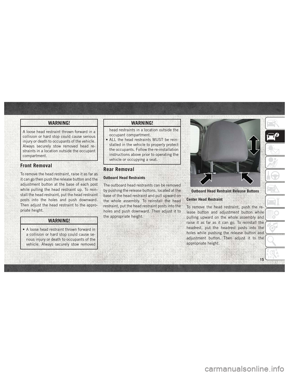
The outboard head restraints can be removed
by pushing the release buttons, located at the
base of the head restraint and pull upward on
the whole assembly. To reinstall the head
restraint, put the head restraint posts into the
holes and push downward. Then adjust it to
the appropriate height. Center Head Restraint
To remove the head restraint, push the re-
lease button and adjustment button while
pulling upward on the whole assembly and
raise it as far as it can go. To reinstall the
headrest, put the headrest posts into the
holes while pushing the release button and
adjustment button. Then adjust it to the
appropriate height.
Outboard Head Restraint Release Buttons
15
Page 18 of 180
WARNING!
• A loose head restraint thrown forward ina collision or hard stop could cause
serious injury or death to occupants of
the vehicle. Always securely stow re-
moved head restraints in a location out-
side the occupant compartment.
• ALL the head restraints MUST be rein-
stalled in the vehicle to properly protect
the occupants. Follow the re-installation
instructions above prior to operating the
vehicle or occupying a seat.
STEERING WHEEL
Tilt/Telescoping Steering Column
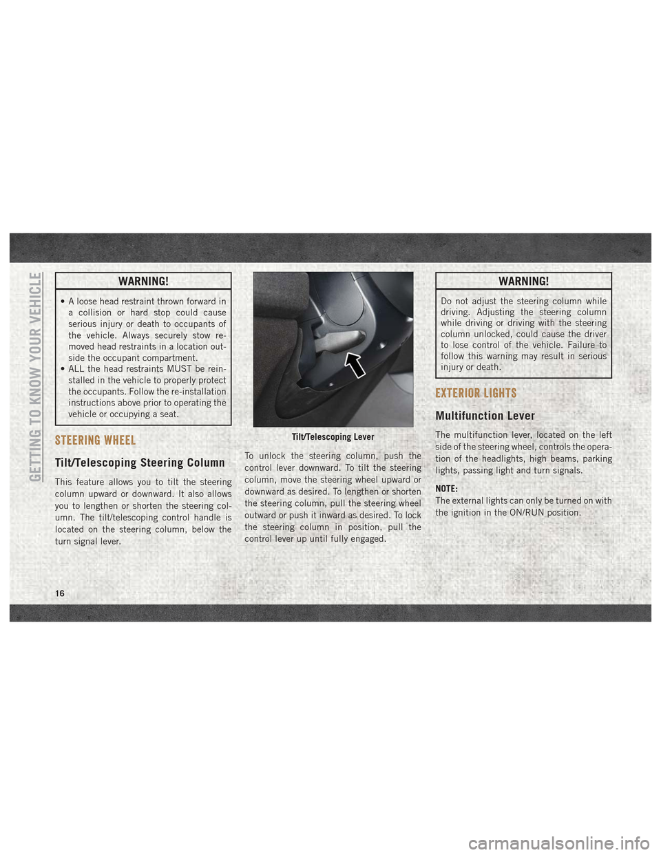
This feature allows you to tilt the steering
column upward or downward. It also allows
you to lengthen or shorten the steering col-
umn. The tilt/telescoping control handle is
located on the steering column, below the
turn signal lever. To unlock the steering column, push the
control lever downward. To tilt the steering
column, move the steering wheel upward or
downward as desired. To lengthen or shorten
the steering column, pull the steering wheel
outward or push it inward as desired. To lock
the steering column in position, pull the
control lever up until fully engaged.
WARNING!
Do not adjust the steering column while
driving. Adjusting the steering column
while driving or driving with the steering
column unlocked, could cause the driver
to lose control of the vehicle. Failure to
follow this warning may result in serious
injury or death.
EXTERIOR LIGHTS
Multifunction Lever
The multifunction lever, located on the left
side of the steering wheel, controls the opera-
tion of the headlights, high beams, parking
lights, passing light and turn signals.
NOTE:
The external lights can only be turned on with
the ignition in the ON/RUN position.Tilt/Telescoping Lever
GETTING TO KNOW YOUR VEHICLE
16
Page 19 of 180
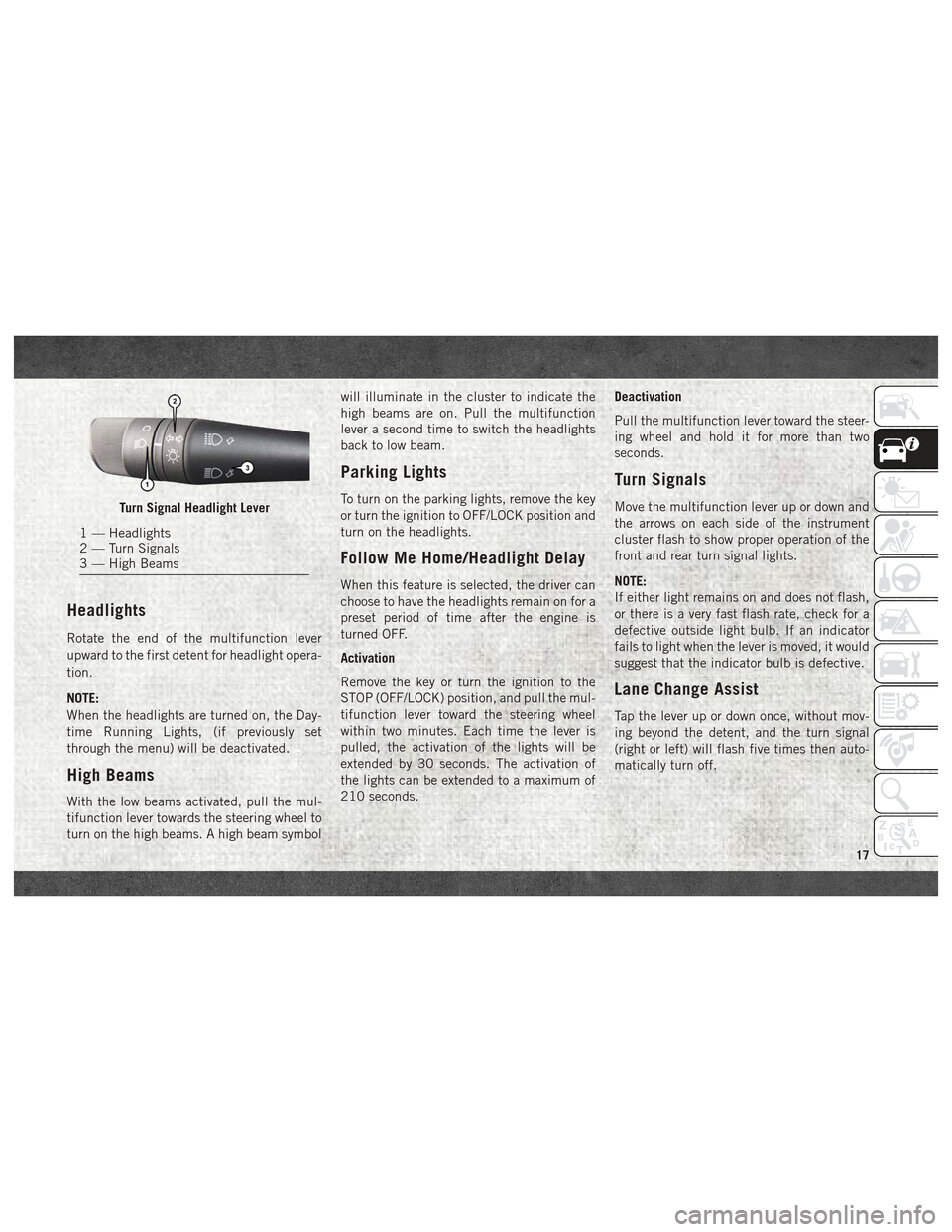
Headlights
Rotate the end of the multifunction lever
upward to the first detent for headlight opera-
tion.
NOTE:
When the headlights are turned on, the Day-
time Running Lights, (if previously set
through the menu) will be deactivated.
High Beams
With the low beams activated, pull the mul-
tifunction lever towards the steering wheel to
turn on the high beams. A high beam symbolwill illuminate in the cluster to indicate the
high beams are on. Pull the multifunction
lever a second time to switch the headlights
back to low beam.
Parking Lights
To turn on the parking lights, remove the key
or turn the ignition to OFF/LOCK position and
turn on the headlights.
Follow Me Home/Headlight Delay
When this feature is selected, the driver can
choose to have the headlights remain on for a
preset period of time after the engine is
turned OFF.
Activation
Remove the key or turn the ignition to the
STOP (OFF/LOCK) position, and pull the mul-
tifunction lever toward the steering wheel
within two minutes. Each time the lever is
pulled, the activation of the lights will be
extended by 30 seconds. The activation of
the lights can be extended to a maximum of
210 seconds.
Deactivation
Pull the multifunction lever toward the steer-
ing wheel and hold it for more than two
seconds.
Turn Signals
Move the multifunction lever up or down and
the arrows on each side of the instrument
cluster flash to show proper operation of the
front and rear turn signal lights.
NOTE:
If either light remains on and does not flash,
or there is a very fast flash rate, check for a
defective outside light bulb. If an indicator
fails to light when the lever is moved, it would
suggest that the indicator bulb is defective.
Lane Change Assist
Tap the lever up or down once, without mov-
ing beyond the detent, and the turn signal
(right or left) will flash five times then auto-
matically turn off.
Turn Signal Headlight Lever
1 — Headlights
2 — Turn Signals
3 — High Beams
17
Page 35 of 180
NOTE:
If the vehicle is moving and a door is opened,
there will also be a single chime.
— Electronic Throttle Control (ETC)
Warning Light
This light informs you of a problem with the
Electronic Throttle Control (ETC) system. If a
problem is detected while the vehicle is run-
ning, the light will either stay on or flash
depending on the nature of the problem.
Cycle the ignition when the vehicle is safely
and completely stopped and the transmission
is placed in the PARK position. The light
should turn off. If the light remains on with
the vehicle running, your vehicle will usually
be drivable; however, see an authorized
dealer for service as soon as possible.
If the light continues to flash when the ve-
hicle is running, immediate service is re-
quired and you may experience reduced per-
formance, an elevated/rough idle, or engine
stall and your vehicle may require towing. The
light will come on when the ignition is placed
in the ON/RUN or MAR/ON/RUN position and remain on briefly as a bulb check. If the light
does not come on during starting, have the
system checked by an authorized dealer.
— Engine Temperature Warning Light
This light warns of an overheated engine
condition. If the engine coolant temperature
is too high, this indicator will illuminate and a
single chime will sound. If the temperature
reaches the upper limit, a continuous chime
will be sound for four minutes or until the
engine is allowed to cool whichever comes
first.
If the light turns on while driving, safely pull
over and stop the vehicle. If the A/C system is
on, turn it off. Also, shift the transmission
into NEUTRAL and idle the vehicle. If the
temperature reading does not return to nor-
mal, turn the engine off immediately and call
for service. Refer to “If Your Engine Over-
heats” in “In Case Of Emergency” for further
information.
— Oil Pressure Warning Light
This light indicates low engine oil pressure. If
the light turns on while driving, stop the
vehicle and shut off the engine as soon as
possible. A chime will sound when this light
turns on.
Do not operate the vehicle until the cause is
corrected. This light does not indicate how
much oil is in the engine. The engine oil level
must be checked under the hood.
— Transmission Temperature Warning
Light — If Equipped
This light indicates that there is excessive
transmission fluid temperature that might
occur with severe usage such as trailer tow-
ing. If this light turns on, stop the vehicle and
run the engine at idle or slightly faster, with
the transmission in PARK or NEUTRAL, until
the light turns off. Once the light turns off,
you may continue to drive normally.
WARNING!
If you continue operating the vehicle when
the Transmission Temperature Warning
33
Page 38 of 180
CAUTION!
The TPMS has been optimized for the
original equipment tires and wheels.
TPMS pressures and warning have been
established for the tire size equipped on
your vehicle. Undesirable system opera-
tion or sensor damage may result when
using replacement equipment that is not
of the same size, type, and/or style. After-
market wheels can cause sensor damage.
Using aftermarket tire sealants may cause
the Tire Pressure Monitoring System
(TPMS) sensor to become inoperable. Af-
ter using an aftermarket tire sealant it is
recommended that you take your vehicle
to your authorized dealer to have your
sensor function checked.
— Vehicle Security Warning Light
This telltale will illuminate when the vehicle
security alarm system has detected an at-
tempt was made to break into the vehicle.
— Engine Check/Malfunction Indica-
tor Warning Light (MIL)
The Engine Check/Malfunction Indicator
Light (MIL) is a part of an Onboard Diagnostic
System called OBD II that monitors engine
and automatic transmission control systems.
The light will illuminate when the ignition is
in the ON/RUN position before engine start.
If the bulb does not come on when turning
the key from OFF to ON/RUN, have the con-
dition checked promptly.
Certain conditions, such as a loose or missing
gas cap, poor quality fuel, etc., may illumi-
nate the light after engine start. The vehicle
should be serviced if the light stays on
through several typical driving styles. In most
situations, the vehicle will drive normally and
will not require towing.
When the engine is running, the MIL may
flash to alert serious conditions that could
lead to immediate loss of power or severe
catalytic converter damage. The vehicle
should be serviced as soon as possible if this
occurs.
WARNING!
A malfunctioning catalytic converter, as
referenced above, can reach higher tem-
peratures than in normal operating condi-
tions. This can cause a fire if you drive
slowly or park over flammable substances
such as dry plants, wood, cardboard, etc.
This could result in death or serious injury
to the driver, occupants or others.
CAUTION!
Prolonged driving with the Malfunction
Indicator Light (MIL) on could cause dam-
age to the vehicle control system. It also
could affect fuel economy and driveability.
If the MIL is flashing, severe catalytic
converter damage and power loss will soon
occur. Immediate service is required.
GETTING TO KNOW YOUR INSTRUMENT PANEL
36
Page 40 of 180
— Front Fog Indicator Light — If
Equipped
This indicator will illuminate when the front
fog lights are on.
— Cruise Control SET Indicator Light
This light will turn on when the speed control
is set to the desired speed. Refer to “Speed
Control” in “Starting And Operating” for fur-
ther information.
Blue Indicator Lights
— High Beam Indicator Light
This indicator shows that the high beam
headlights are on. With the low beams acti-
vated, push the multifunction lever forward
(toward the front of the vehicle) to turn on the
high beams. Pull the multifunction lever rear-
ward (toward the rear of the vehicle) to turn
off the high beams. Pull the lever toward you
for a temporary high beam on, "flash to pass"
scenario.
ONBOARD DIAGNOSTIC SYSTEM —
OBD II
Your vehicle is equipped with a sophisticated
Onboard Diagnostic system called OBD II.
This system monitors the performance of the
emissions, engine, and transmission control
systems. When these systems are operating
properly, your vehicle will provide excellent
performance and fuel economy, as well as
engine emissions well within current govern-
ment regulations.
If any of these systems require service, the
OBD II system will turn on the Malfunction
Indicator Light (MIL). It will also store diag-
nostic codes and other information to assist
your service technician in making repairs.
Although your vehicle will usually be drivable
and not need towing, see your authorized
dealer for service as soon as possible.
CAUTION!
• Prolonged driving with the MIL on could cause further damage to the emission
control system. It could also affect fuel
CAUTION!
economy and driveability. The vehicle
must be serviced before any emissions
tests can be performed.
• If the MIL is flashing while the vehicle is
running, severe catalytic converter dam-
age and power loss will soon occur. Im-
mediate service is required.
Onboard Diagnostic System (OBD
II) Cybersecurity
Your vehicle is required to have an Onboard
Diagnostic system (OBD II) and a connection
port to allow access to information related to
the performance of your emissions controls.
Authorized service technicians may need to
access this information to assist with the
diagnosis and service of your vehicle and
emissions system.
WARNING!
• ONLY an authorized service technicianshould connect equipment to the OBD IIGETTING TO KNOW YOUR INSTRUMENT PANEL
38
Page 49 of 180
BeltAlert warning sequence starts by blinking
the Seat Belt Reminder Light and sounding
an intermittent chime. Once the BeltAlert
warning sequence has completed, the Seat
Belt Reminder Light will remain on until the
seat belts are buckled. The BeltAlert warning
sequence may repeat based on vehicle speed
until the driver and occupied outboard front
seat passenger seat belts are buckled. The
driver should instruct all occupants to buckle
their seat belts.
Change of Status
If the driver or outboard front seat passenger
(if equipped with outboard front passenger
seat BeltAlert) unbuckles their seat belt while
the vehicle is traveling, the BeltAlert warning
sequence will begin until the seat belts are
buckled again.
The outboard front passenger seat BeltAlert
is not active when the outboard front passen-
ger seat is unoccupied. BeltAlert may be
triggered when an animal or other items are
placed on the outboard front passenger seat
or when the seat is folded flat (if equipped). It
is recommended that pets be restrained inthe rear seat (if equipped) in pet harnesses or
pet carriers that are secured by seat belts,
and cargo is properly stowed.
BeltAlert can be activated or deactivated by
your authorized dealer. FCA US LLC does not
recommend deactivating BeltAlert.
NOTE:
If BeltAlert has been deactivated and the
driver or outboard front seat passenger (if
equipped with outboard front passenger seat
BeltAlert) is unbuckled the Seat Belt Re-
minder Light will turn on and remain on until
the driver and outboard front seat passenger
seat belts are buckled.
Lap/Shoulder Belts
All seating positions in your vehicle are
equipped with lap/shoulder belts.
The seat belt webbing retractor will lock only
during very sudden stops or collisions. This
feature allows the shoulder part of the seat
belt to move freely with you under normal
conditions. However, in a collision the seat
belt will lock and reduce your risk of striking
the inside of the vehicle or being thrown out
of the vehicle.
WARNING!
• Relying on the air bags alone could lead
to more severe injuries in a collision. The
air bags work with your seat belt to
restrain you properly. In some collisions,
the air bags won’t deploy at all. Always
wear your seat belt even though you have
air bags.
• In a collision, you and your passengers
can suffer much greater injuries if you
are not properly buckled up. You can
strike the interior of your vehicle or other
passengers, or you can be thrown out of
the vehicle. Always be sure you and
others in your vehicle are buckled up
properly.
• It is dangerous to ride in a cargo area,
inside or outside of a vehicle. In a colli-
sion, people riding in these areas are
more likely to be seriously injured or
killed.
• Do not allow people to ride in any area of
your vehicle that is not equipped with
seats and seat belts.
47
Page 51 of 180
Lap/Shoulder Belt Operating Instructions
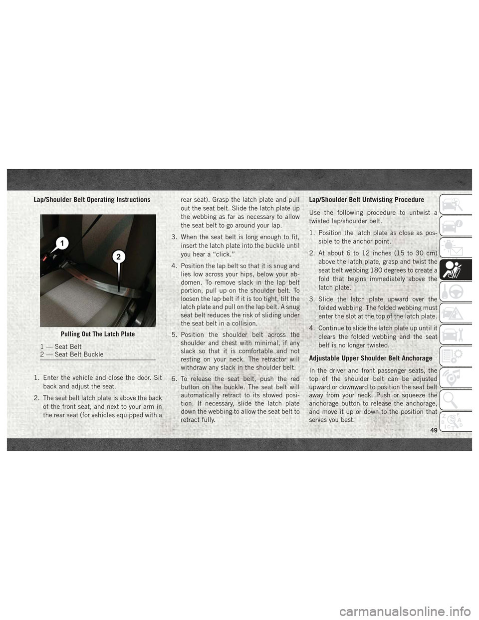
1. Enter the vehicle and close the door. Sitback and adjust the seat.
2. The seat belt latch plate is above the back of the front seat, and next to your arm in
the rear seat (for vehicles equipped with a rear seat). Grasp the latch plate and pull
out the seat belt. Slide the latch plate up
the webbing as far as necessary to allow
the seat belt to go around your lap.
3. When the seat belt is long enough to fit, insert the latch plate into the buckle until
you hear a “click.”
4. Position the lap belt so that it is snug and lies low across your hips, below your ab-
domen. To remove slack in the lap belt
portion, pull up on the shoulder belt. To
loosen the lap belt if it is too tight, tilt the
latch plate and pull on the lap belt. A snug
seat belt reduces the risk of sliding under
the seat belt in a collision.
5. Position the shoulder belt across the shoulder and chest with minimal, if any
slack so that it is comfortable and not
resting on your neck. The retractor will
withdraw any slack in the shoulder belt.
6. To release the seat belt, push the red button on the buckle. The seat belt will
automatically retract to its stowed posi-
tion. If necessary, slide the latch plate
down the webbing to allow the seat belt to
retract fully.
Lap/Shoulder Belt Untwisting Procedure
Use the following procedure to untwist a
twisted lap/shoulder belt.
1. Position the latch plate as close as pos-
sible to the anchor point.
2. At about 6 to 12 inches (15 to 30 cm) above the latch plate, grasp and twist the
seat belt webbing 180 degrees to create a
fold that begins immediately above the
latch plate.
3. Slide the latch plate upward over the folded webbing. The folded webbing must
enter the slot at the top of the latch plate.
4. Continue to slide the latch plate up until it clears the folded webbing and the seat
belt is no longer twisted.
Adjustable Upper Shoulder Belt Anchorage
In the driver and front passenger seats, the
top of the shoulder belt can be adjusted
upward or downward to position the seat belt
away from your neck. Push or squeeze the
anchorage button to release the anchorage,
and move it up or down to the position that
serves you best.
Pulling Out The Latch Plate
1 — Seat Belt
2 — Seat Belt Buckle
49
Page 70 of 180
To Install A LATCH-Compatible Child Re-
straint In Vehicles With Rear Seating
If the selected seating position has a Switch-
able Automatic Locking Retractor (ALR) seat
belt, stow the seat belt, following the instruc-
tions below. See the section “Installing Child
Restraints Using the Vehicle Seat Belt” to
check what type of seat belt each seating
position has.
1. Loosen the adjusters on the lower strapsand on the tether strap of the child seat so
that you can more easily attach the hooks
or connectors to the vehicle anchorages.
2. Place the child seat between the lower anchorages for that seating position. For
some second row seats, you may need to
recline the seat and / or raise the head
restraint to get a better fit. If the rear seat
can be moved forward and rearward in the
vehicle, you may wish to move it to its
rear-most position to make room for the
child seat. You may also move the front
seat forward to allow more room for the
child seat. 3. Attach the lower hooks or connectors of
the child restraint to the lower anchorages
in the selected seating position.
4. If the child restraint has a tether strap, connect it to the top tether anchorage.
See the section “Installing Child Re-
straints Using the Top Tether Anchorage”
for directions to attach a tether anchor.
5. Tighten all of the straps as you push the child restraint rearward and downward
into the seat. Remove slack in the straps
according to the child restraint manufac-
turer’s instructions.
6. Test that the child restraint is installed tightly by pulling back and forth on the
child seat at the belt path. It should not
move more than 1 inch (25.4 mm) in any
direction.
How To Stow An Unused Switchable-ALR
(ALR) Seat Belt
When using the LATCH attaching system to
install a child restraint, stow all ALR seat
belts that are not being used by other occu-
pants or being used to secure child restraints.
An unused belt could injure a child if they play with it and accidentally lock the seat belt
retractor. Before installing a child restraint
using the LATCH system, buckle the seat belt
behind the child restraint and out of the
child’s reach. If the buckled seat belt inter-
feres with the child restraint installation,
instead of buckling it behind the child re-
straint, route the seat belt through the child
restraint belt path and then buckle it. Do not
lock the seat belt. Remind all children in the
vehicle that the seat belts are not toys and
that they should not play with them.
WARNING!
• Improper installation of a child restraint
to the LATCH anchorages can lead to
failure of the restraint. The child could
be badly injured or killed. Follow the
child restraint manufacturer’s directions
exactly when installing an infant or child
restraint.
• Child restraint anchorages are designed
to withstand only those loads imposed
by correctly-fitted child restraints. Un-
der no circumstances are they to be
used for adult seat belts, harnesses, or
SAFETY
68
Page 79 of 180
WARNING!
clutch pedals and cause a loss of vehicle
control. To prevent SERIOUS INJURY or
DEATH:
• ALWAYS securely attach
your floor
mat using the floor mat fasteners. DO
NOT install your floor mat upside down
or turn your floor mat over. Lightly pull to
confirm mat is secured using the floor
mat fasteners on a regular basis.
• ALWAYS REMOVE THE EXISTING
FLOOR MAT FROM THE VEHICLE
before installing any other floor mat.
NEVER install or stack an additional
floor mat on top of an existing floor mat.
• ONLY install floor mats designed to fit
your vehicle. NEVER install a floor mat
that cannot be properly attached and
secured to your vehicle. If a floor mat
needs to be replaced, only use a FCA
approved floor mat for the specific
make, model, and year of your vehicle.
WARNING!
• ONLY use the driver’s side floor mat onthe driver’s side floor area. To check for
interference, with the vehicle properly
parked with the engine off, fully depress
the accelerator, the brake, and the
clutch pedal (if present) to check for
interference. If your floor mat interferes
with the operation of any pedal, or is not
secure to the floor, remove the floor mat
from the vehicle and place the floor mat
in your trunk.
• ONLY use the passenger’s side floor mat
on the passenger’s side floor area.
• ALWAYS make sure objects cannot fall
or slide into the driver’s side floor area
when the vehicle is moving. Objects can
become trapped under accelerator,
brake, or clutch pedals and could cause
a loss of vehicle control.
• NEVER place any objects under the floor
mat (e.g., towels, keys, etc.). These ob-
WARNING!
jects could change the position of the
floor mat and may cause interference
with the accelerator, brake, or clutch
pedals.
• If the vehicle carpet has been removed
and re-installed, always properly attach
carpet to the floor and check the floor
mat fasteners are secure to the vehicle
carpet. Fully depress each pedal to
check for interference with the accelera-
tor, brake, or clutch pedals then re-
install the floor mats.
• It is recommended to only use mild soap
and water to clean your floor mats. After
cleaning, always check your floor mat
has been properly installed and is se-
cured to your vehicle using the floor mat
fasteners by lightly pulling mat.
77