ECU Ram ProMaster City 2018 Owner's Manual
[x] Cancel search | Manufacturer: RAM, Model Year: 2018, Model line: ProMaster City, Model: Ram ProMaster City 2018Pages: 180, PDF Size: 7.52 MB
Page 79 of 180
WARNING!
clutch pedals and cause a loss of vehicle
control. To prevent SERIOUS INJURY or
DEATH:
• ALWAYS securely attach
your floor
mat using the floor mat fasteners. DO
NOT install your floor mat upside down
or turn your floor mat over. Lightly pull to
confirm mat is secured using the floor
mat fasteners on a regular basis.
• ALWAYS REMOVE THE EXISTING
FLOOR MAT FROM THE VEHICLE
before installing any other floor mat.
NEVER install or stack an additional
floor mat on top of an existing floor mat.
• ONLY install floor mats designed to fit
your vehicle. NEVER install a floor mat
that cannot be properly attached and
secured to your vehicle. If a floor mat
needs to be replaced, only use a FCA
approved floor mat for the specific
make, model, and year of your vehicle.
WARNING!
• ONLY use the driver’s side floor mat onthe driver’s side floor area. To check for
interference, with the vehicle properly
parked with the engine off, fully depress
the accelerator, the brake, and the
clutch pedal (if present) to check for
interference. If your floor mat interferes
with the operation of any pedal, or is not
secure to the floor, remove the floor mat
from the vehicle and place the floor mat
in your trunk.
• ONLY use the passenger’s side floor mat
on the passenger’s side floor area.
• ALWAYS make sure objects cannot fall
or slide into the driver’s side floor area
when the vehicle is moving. Objects can
become trapped under accelerator,
brake, or clutch pedals and could cause
a loss of vehicle control.
• NEVER place any objects under the floor
mat (e.g., towels, keys, etc.). These ob-
WARNING!
jects could change the position of the
floor mat and may cause interference
with the accelerator, brake, or clutch
pedals.
• If the vehicle carpet has been removed
and re-installed, always properly attach
carpet to the floor and check the floor
mat fasteners are secure to the vehicle
carpet. Fully depress each pedal to
check for interference with the accelera-
tor, brake, or clutch pedals then re-
install the floor mats.
• It is recommended to only use mild soap
and water to clean your floor mats. After
cleaning, always check your floor mat
has been properly installed and is se-
cured to your vehicle using the floor mat
fasteners by lightly pulling mat.
77
Page 88 of 180
NOTE:
When towing your vehicle, always follow ap-
plicable state and provincial laws. Contact
state and provincial Highway Safety offices
for additional details.
Recreational Towing — Automatic
Transmission
Recreational towing is allowedONLYif the
front wheels are OFFthe ground. This may be
accomplished using a tow dolly or vehicle
trailer. If using a tow dolly, follow this proce-
dure:
1. Properly secure the dolly to the tow ve- hicle, following the dolly manufacturer's
instructions. 2. Drive the front wheels onto the tow dolly.
3. Firmly apply the parking brake. Place the
transmission in PARK.
4. Properly secure the front wheels to the dolly, following the dolly manufacturer's
instructions.
5. Release the parking brake.
CAUTION!
• DO NOT flat tow this vehicle. Damage to the drivetrain will result. If this vehicle
requires towing, make sure the drive
wheels are OFF the ground.
CAUTION!
• Towing this vehicle in violation of theabove requirements can cause severe
transmission damage. Damage from im-
proper towing is not covered under the
New Vehicle Limited Warranty.
STARTING AND OPERATING
86
Page 97 of 180
• When winching the tire back into place, thewinch will make three audible noises once
secure. Reach underneath and shake tire
by hand to confirm that it is secure. The tire
should not move. If tire is still loose and/or
three audible noises are not heard, place
and secure damaged wheel into the vehicle
and seek dealer assistance for the winch
mechanism.
Preparations For Jacking
1. Park the vehicle on a firm level surface as
far from the edge of the roadway as pos-
sible. Avoid icy or slippery areas.
WARNING!
Do not attempt to change a tire on the side
of the vehicle close to moving traffic, pull
far enough off the road to avoid being hit
when operating the jack or changing the
wheel.
2. Turn on the Hazard Warning flasher.
3. Apply the parking brake. 4. Place the gear selector into PARK.
5. Turn the ignition off to the LOCK position.
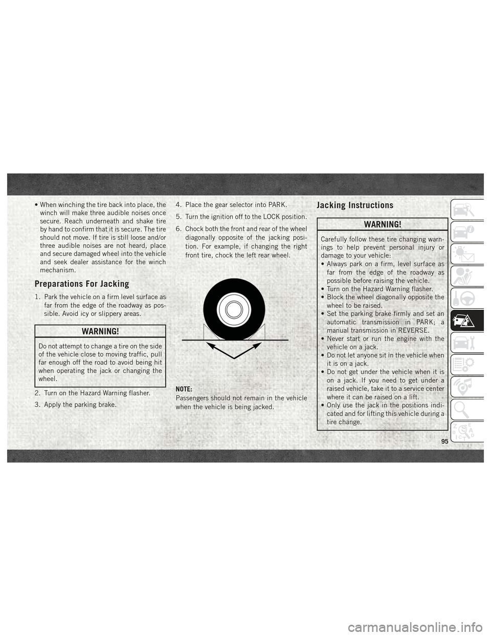
6. Chock both the front and rear of the wheel
diagonally opposite of the jacking posi-
tion. For example, if changing the right
front tire, chock the left rear wheel.
NOTE:
Passengers should not remain in the vehicle
when the vehicle is being jacked.
Jacking Instructions
WARNING!
Carefully follow these tire changing warn-
ings to help prevent personal injury or
damage to your vehicle:
• Always park on a firm, level surface as far from the edge of the roadway as
possible before raising the vehicle.
• Turn on the Hazard Warning flasher.
• Block the wheel diagonally opposite the
wheel to be raised.
• Set the parking brake firmly and set an
automatic transmission in PARK; a
manual transmission in REVERSE.
• Never start or run the engine with the
vehicle on a jack.
• Do not let anyone sit in the vehicle when
it is on a jack.
• Do not get under the vehicle when it is
on a jack. If you need to get under a
raised vehicle, take it to a service center
where it can be raised on a lift.
• Only use the jack in the positions indi-
cated and for lifting this vehicle during a
tire change.
95
Page 98 of 180
WARNING!
• If working on or near a roadway, beextremely careful of motor traffic.
• To assure that spare tires, flat or in-
flated, are securely stowed, spares must
be stowed with the valve stem facing the
ground.
• The stowed spare tire should always be
checked for security by pushing on it
with your hand , at the location under
the rear bumper, behind the vehicle. The
spare tire should not move when fully
secured by the winch under the vehicle.
CAUTION!
Do not attempt to raise the vehicle by
jacking on locations other than those indi-
cated in the Jacking Instructions for this
vehicle.
1. Loosen (but do not remove) the wheel lug bolts with the wrench handle by turning
them to the left one turn while the wheel
is still on the ground. 2. There are two jack engagement locations
on each side of the vehicle body.
NOTE:
Place the jack underneath the jack engage-
ment location that is closest to the flat tire.
WARNING!
Being under a jacked-up vehicle is danger-
ous. The vehicle could slip off the jack and
fall on you. You could be crushed. Never
get any part of your body under a vehicle
that is on a jack. If you need to get under a
raised vehicle, take it to a service center
where it can be raised on a lift.
CAUTION!
Do not attempt to raise the vehicle by
jacking on locations other than those indi-
cated in the Jacking Instructions for this
vehicle.
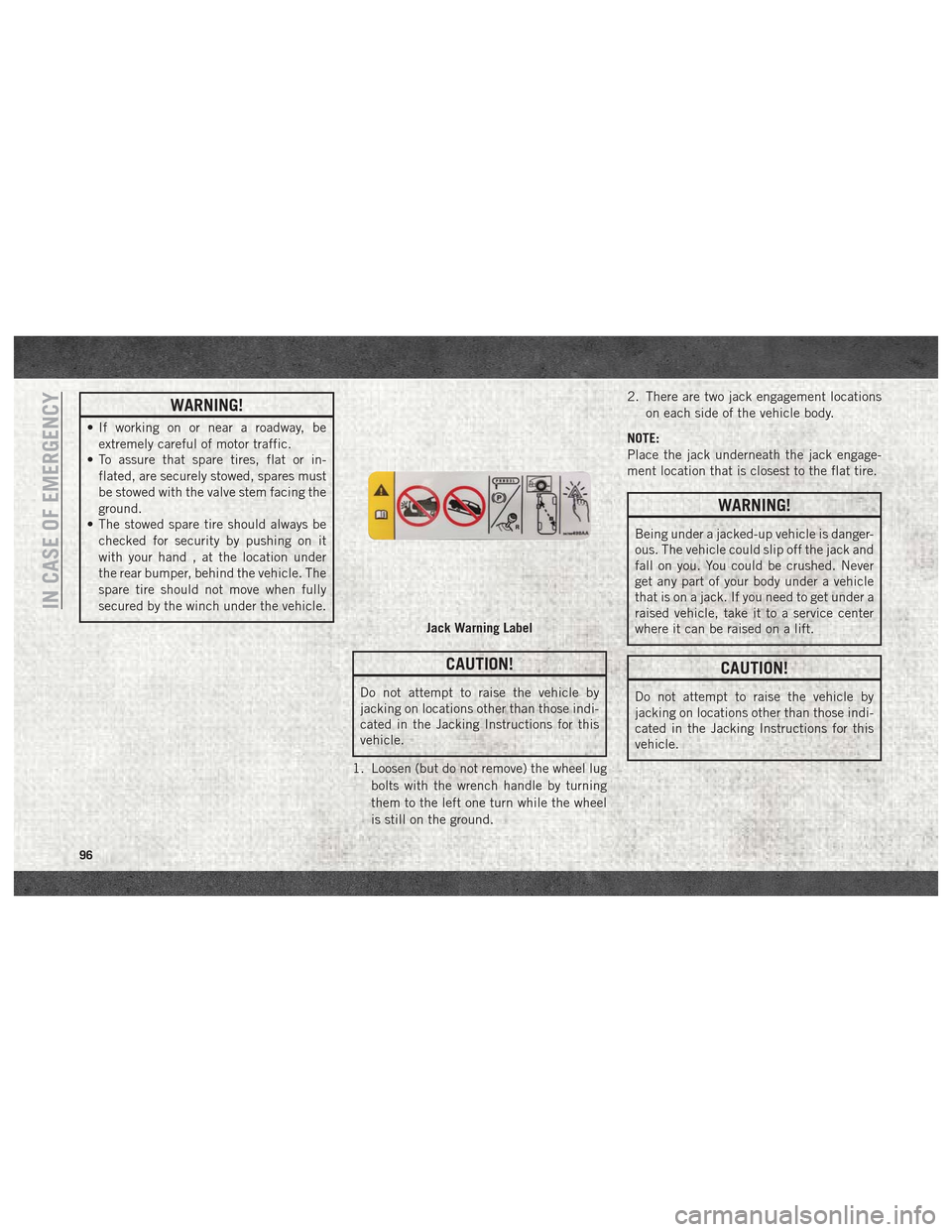
Jack Warning Label
IN CASE OF EMERGENCY
96
Page 99 of 180
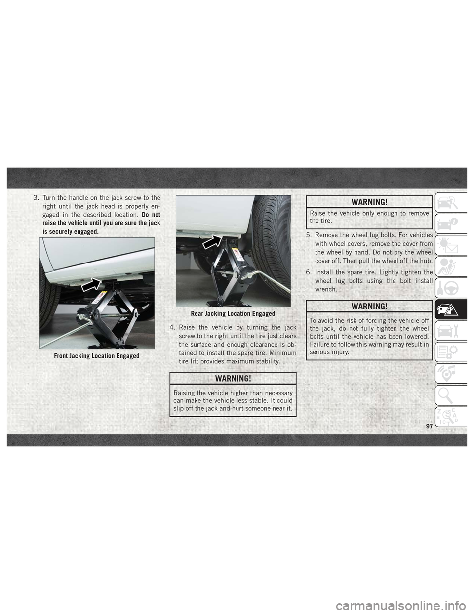
3. Turn the handle on the jack screw to theright until the jack head is properly en-
gaged in the described location. Do not
raise the vehicle until you are sure the jack
is securely engaged.
4. Raise the vehicle by turning the jackscrew to the right until the tire just clears
the surface and enough clearance is ob-
tained to install the spare tire. Minimum
tire lift provides maximum stability.
WARNING!
Raising the vehicle higher than necessary
can make the vehicle less stable. It could
slip off the jack and hurt someone near it.
WARNING!
Raise the vehicle only enough to remove
the tire.
5. Remove the wheel lug bolts. For vehicles with wheel covers, remove the cover from
the wheel by hand. Do not pry the wheel
cover off. Then pull the wheel off the hub.
6. Install the spare tire. Lightly tighten the wheel lug bolts using the bolt install
wrench.
WARNING!
To avoid the risk of forcing the vehicle off
the jack, do not fully tighten the wheel
bolts until the vehicle has been lowered.
Failure to follow this warning may result in
serious injury.
Front Jacking Location Engaged
Rear Jacking Location Engaged
97
Page 100 of 180
CAUTION!
Be sure to mount the spare tire with the
valve stem facing outward. The vehicle
could be damaged if the spare tire is
mounted incorrectly.
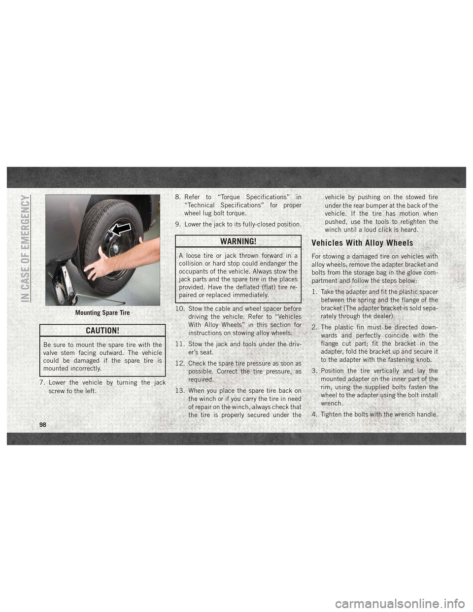
7. Lower the vehicle by turning the jack screw to the left. 8. Refer to “Torque Specifications” in
“Technical Specifications” for proper
wheel lug bolt torque.
9. Lower the jack to its fully-closed position.
WARNING!
A loose tire or jack thrown forward in a
collision or hard stop could endanger the
occupants of the vehicle. Always stow the
jack parts and the spare tire in the places
provided. Have the deflated (flat) tire re-
paired or replaced immediately.
10. Stow the cable and wheel spacer before driving the vehicle. Refer to “Vehicles
With Alloy Wheels” in this section for
instructions on stowing alloy wheels.
11. Stow the jack and tools under the driv- er’s seat.
12. Check the spare tire pressure as soon as possible. Correct the tire pressure, as
required.
13. When you place the spare tire back on the winch or if you carry the tire in need
of repair on the winch, always check that
the tire is properly secured under the vehicle by pushing on the stowed tire
under the rear bumper at the back of the
vehicle. If the tire has motion when
pushed, use the tools to retighten the
winch until a loud click is heard.
Vehicles With Alloy Wheels
For stowing a damaged tire on vehicles with
alloy wheels, remove the adapter bracket and
bolts from the storage bag in the glove com-
partment and follow the steps below:
1. Take the adapter and fit the plastic spacer
between the spring and the flange of the
bracket (The adapter bracket is sold sepa-
rately through the dealer).
2. The plastic fin must be directed down- wards and perfectly coincide with the
flange cut part; fit the bracket in the
adapter, fold the bracket up and secure it
to the adapter with the fastening knob.
3. Position the tire vertically and lay the mounted adapter on the inner part of the
rim, using the supplied bolts fasten the
wheel to the adapter using the bolt install
wrench.
4. Tighten the bolts with the wrench handle.
Mounting Spare Tire
IN CASE OF EMERGENCY
98
Page 101 of 180
5. Rotate the winch mechanism clockwiseuntil the wheel is properly stowed under
the vehicle and until the wench makes
three audible noises.
6. Reach underneath and shake tire by hand to confirm that it is secure. The tire should
not move. If the tire is still loose and/or
three audible noises are not heard, place
and secure damaged wheel into the ve-
hicle and seek dealer assistance for the
winch mechanism.
This is for temporary use only.
Vehicles Equipped With Wheel
Covers
1. Mount the road tire on the axle.
2. To ease the installation process for steel wheels with wheel covers, install two
wheel bolts on the wheel. Install the wheel
bolts with the threaded end of the bolt
toward the wheel. Lightly tighten the
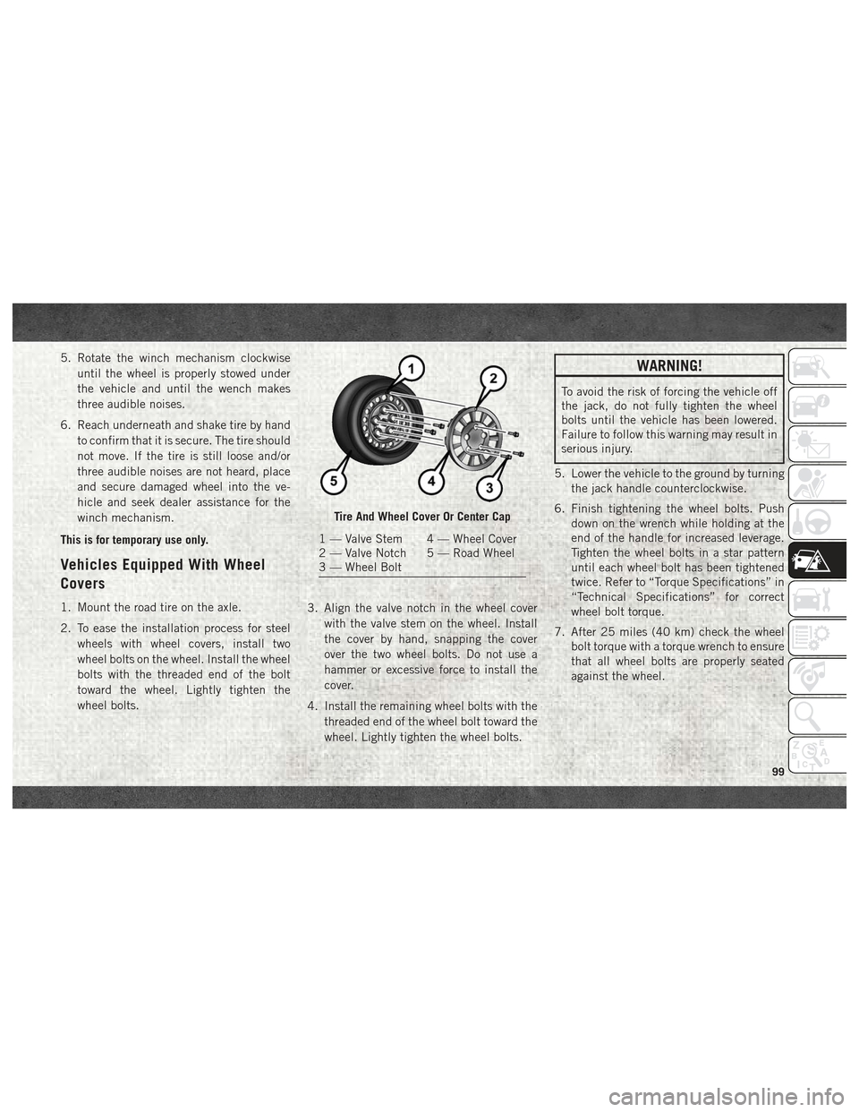
wheel bolts. 3. Align the valve notch in the wheel cover
with the valve stem on the wheel. Install
the cover by hand, snapping the cover
over the two wheel bolts. Do not use a
hammer or excessive force to install the
cover.
4. Install the remaining wheel bolts with the threaded end of the wheel bolt toward the
wheel. Lightly tighten the wheel bolts.
WARNING!
To avoid the risk of forcing the vehicle off
the jack, do not fully tighten the wheel
bolts until the vehicle has been lowered.
Failure to follow this warning may result in
serious injury.
5. Lower the vehicle to the ground by turning the jack handle counterclockwise.
6. Finish tightening the wheel bolts. Push down on the wrench while holding at the
end of the handle for increased leverage.
Tighten the wheel bolts in a star pattern
until each wheel bolt has been tightened
twice. Refer to “Torque Specifications” in
“Technical Specifications” for correct
wheel bolt torque.
7. After 25 miles (40 km) check the wheel bolt torque with a torque wrench to ensure
that all wheel bolts are properly seated
against the wheel.
Tire And Wheel Cover Or Center Cap
1 — Valve Stem 4 — Wheel Cover
2 — Valve Notch 5 — Road Wheel
3 — Wheel Bolt
99
Page 143 of 180
MULTIMEDIA
CYBERSECURITY..............142
UCONNECT 3/3 NAV WITH 5-INCH
DISPLAY .................. .143
Clock Setting.................144
Equalizer, Balance And Fade .......144
Radio Operation ...............146
USB/Audio Jack (AUX)/Bluetooth
Operation ...................147
Navigation ..................148
UCONNECT SETTINGS ...........148
STEERING WHEEL AUDIO CONTROLS . .149
Left Switch ..................149
Right Switch .................149
UCONNECT PHONE ............150
Uconnect Phone (Bluetooth Hands Free
Calling)....................150 Pairing (Wirelessly Connecting) Your
Mobile Phone To The Uconnect
System
....................151
Common Phone Commands
(Examples) ..................154
Mute (Or Unmute) Microphone
During Call ..................154
Transfer Ongoing Call Between Handset
And Vehicle .................154
Phonebook ..................154
Voice Command Tips ............154
Changing The Volume ............155
Using Do Not Disturb ...........155
Incoming Text Messages ..........156
Helpful Tips And Common Questions To
Improve Bluetooth Performance With
Your Uconnect System ...........157 Regulatory And Safety Information
USA/CANADA
................157
UCONNECT VOICE RECOGNITION
QUICK TIPS................ .158
Introducing Uconnect............158
Get Started ..................159
Basic Voice Commands ...........159
Radio .....................160
Media .....................160
Phone .....................160
Voice Text Reply ...............161
General Information .............162
Additional Information ...........162
MULTIMEDIA
141
Page 144 of 180
CYBERSECURITY
Your vehicle may be a connected vehicle and
may be equipped with both wired and wire-
less networks. These networks allow your
vehicle to send and receive information. This
information allows systems and features in
your vehicle to function properly.
Your vehicle may be equipped with certain
security features to reduce the risk of unau-
thorized and unlawful access to vehicle sys-
tems and wireless communications. Vehicle
software technology continues to evolve over
time and FCA US LLC, working with its sup-
pliers, evaluates and takes appropriate steps
as needed. Similar to a computer or other
devices, your vehicle may require software
updates to improve the usability and perfor-
mance of your systems or to reduce the po-
tential risk of unauthorized and unlawful ac-
cess to your vehicle systems.
The risk of unauthorized and unlawful access
to your vehicle systems may still exist, even if
the most recent version of vehicle software
(such as Uconnect software) is installed.
WARNING!
• It is not possible to know or to predict allof the possible outcomes if your vehi-
cle’s systems are breached. It may be
possible that vehicle systems, including
safety related systems, could be im-
paired or a loss of vehicle control could
occur that may result in an accident
involving serious injury or death.
• ONLY insert media (e.g., USB, SD card,
or CD) into your vehicle if it came from a
trusted source. Media of unknown origin
could possibly contain malicious soft-
ware, and if installed in your vehicle, it
may increase the possibility for vehicle
systems to be breached.
• As always, if you experience unusual
vehicle behavior, take your vehicle to
your nearest authorized dealer immedi-
ately.
NOTE:
• FCA or your dealer may contact you directly regarding software updates. • To help further improve vehicle security
and minimize the potential risk of a secu-
rity breach, vehicle owners should: – Routinely check
www.driveuconnect.com/software-update
to learn about available Uconnect soft-
ware updates.
– Only connect and use trusted media devices (e.g. personal mobile phones,
USBs, CDs).
Privacy of any wireless and wired communi-
cations cannot be assured. Third parties may
unlawfully intercept information and private
communications without your consent. For
further information, refer to “Onboard Diag-
nostic System (OBD II) Cybersecurity” in
“Getting To Know Your Instrument Panel” in
your Owner’s Manual at www.mopar.com/
en-us/care/owners-manual.html (U.S. Resi-
dents) or www.owners.mopar.ca (Canadian
Residents) for further information.
MULTIMEDIA
142