warning light Ram ProMaster City 2018 Owner's Manual
[x] Cancel search | Manufacturer: RAM, Model Year: 2018, Model line: ProMaster City, Model: Ram ProMaster City 2018Pages: 180, PDF Size: 7.52 MB
Page 56 of 180
NOTE:
If the speedometer, tachometer, or any en-
gine related gauges are not working, the Oc-
cupant Restraint Controller (ORC) may also
be disabled. In this condition the air bags
may not be ready to inflate for your protec-
tion. Have an authorized dealer service the
air bag system immediately.
WARNING!
Ignoring the Air Bag Warning Light in your
instrument panel could mean you won’t
have the air bag system to protect you in a
collision. If the light does not come on as a
bulb check when the ignition is first
turned on, stays on after you start the
vehicle, or if it comes on as you drive, have
an authorized dealer service the air bag
system immediately.
Front Air Bags
This vehicle has front air bags and lap/
shoulder belts for both the driver and front
passenger. The front air bags are a supple-
ment to the seat belt restraint systems. The
driver front air bag is mounted in the centerof the steering wheel. The passenger front air
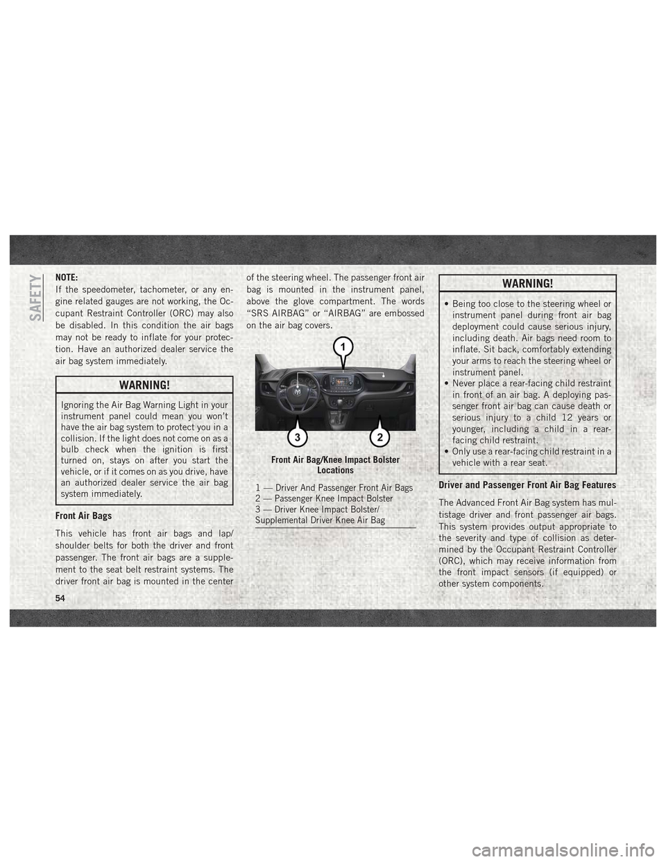
bag is mounted in the instrument panel,
above the glove compartment. The words
“SRS AIRBAG” or “AIRBAG” are embossed
on the air bag covers.
WARNING!
• Being too close to the steering wheel or
instrument panel during front air bag
deployment could cause serious injury,
including death. Air bags need room to
inflate. Sit back, comfortably extending
your arms to reach the steering wheel or
instrument panel.
• Never place a rear-facing child restraint
in front of an air bag. A deploying pas-
senger front air bag can cause death or
serious injury to a child 12 years or
younger, including a child in a rear-
facing child restraint.
• Only use a rear-facing child restraint in a
vehicle with a rear seat.
Driver and Passenger Front Air Bag Features
The Advanced Front Air Bag system has mul-
tistage driver and front passenger air bags.
This system provides output appropriate to
the severity and type of collision as deter-
mined by the Occupant Restraint Controller
(ORC), which may receive information from
the front impact sensors (if equipped) or
other system components.
Front Air Bag/Knee Impact Bolster Locations
1—Driver And Passenger Front Air Bags
2 — Passenger Knee Impact Bolster
3 — Driver Knee Impact Bolster/
Supplemental Driver Knee Air Bag
SAFETY
54
Page 58 of 180
Knee Impact Bolsters
The Knee Impact Bolsters help protect the
knees of the driver and front passenger, and
position the front occupants for improved
interaction with the front air bags.
WARNING!
• Do not drill, cut, or tamper with the kneeimpact bolsters in any way.
• Do not mount any accessories to the
knee impact bolsters such as alarm
lights, stereos, citizen band radios, etc.
Supplemental Driver Knee Air Bag
This vehicle is equipped with a Supplemental
Driver Knee Air Bag mounted in the instru-
ment panel below the steering column. The
Supplemental Driver Knee Air Bag provides
enhanced protection during a frontal impact
by working together with the seat belts, pre-
tensioners, and front air bags.
Supplemental Side Air Bags
Supplemental Seat-Mounted Side Air Bags
(SABs)
This vehicle is equipped with Supplemental
Seat-Mounted Side Air Bags (SABs).
Supplemental Seat-Mounted Side Air Bags
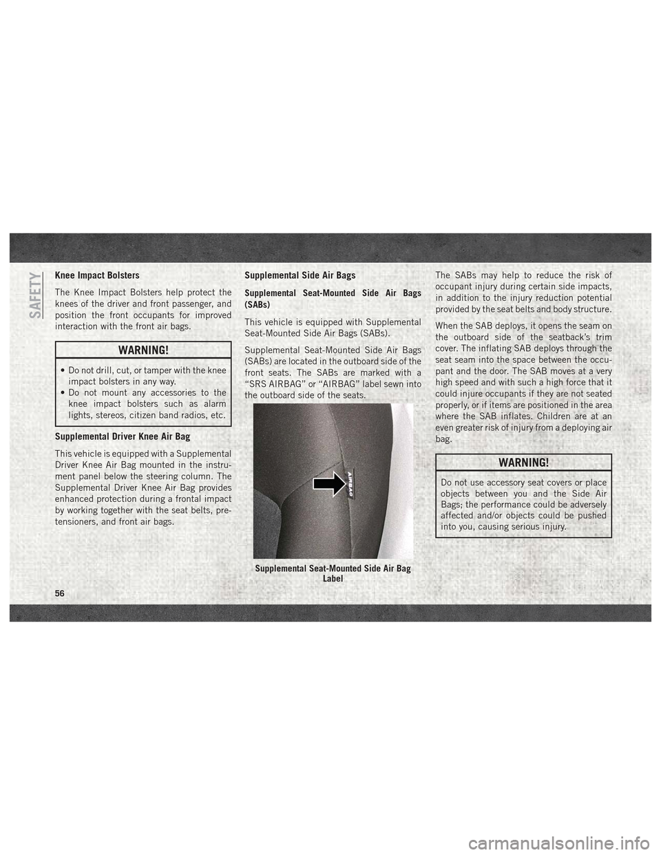
(SABs) are located in the outboard side of the
front seats. The SABs are marked with a
“SRS AIRBAG” or “AIRBAG” label sewn into
the outboard side of the seats. The SABs may help to reduce the risk of
occupant injury during certain side impacts,
in addition to the injury reduction potential
provided by the seat belts and body structure.
When the SAB deploys, it opens the seam on
the outboard side of the seatback’s trim
cover. The inflating SAB deploys through the
seat seam into the space between the occu-
pant and the door. The SAB moves at a very
high speed and with such a high force that it
could injure occupants if they are not seated
properly, or if items are positioned in the area
where the SAB inflates. Children are at an
even greater risk of injury from a deploying air
bag.
WARNING!
Do not use accessory seat covers or place
objects between you and the Side Air
Bags; the performance could be adversely
affected and/or objects could be pushed
into you, causing serious injury.
Supplemental Seat-Mounted Side Air Bag
Label
SAFETY
56
Page 61 of 180
rollover or near rollover event, and deploy-
ment of the Side Air Bags is appropriate, the
rollover sensing system will also deploy the
seat belt pretensioners on both sides of the
vehicle.
The SABICs may help reduce the risk of
partial or complete ejection of vehicle occu-
pants through side windows in certain roll-
over or side impact events.
Air Bag System Components
NOTE:
The Occupant Restraint Controller (ORC)
monitors the internal circuits and intercon-
necting wiring associated with electrical Air
Bag System Components listed below:
• Occupant Restraint Controller (ORC)
• Air Bag Warning Light
• Steering Wheel and Column
• Instrument Panel
• Knee Impact Bolsters
• Driver and Front Passenger Air Bags
• Seat Belt Buckle Switch
• Supplemental Side Air Bags• Supplemental Knee Air Bags
• Front and Side Impact Sensors
• Seat Belt Pretensioners
If A Deployment Occurs
The front air bags are designed to deflate
immediately after deployment.
NOTE:
Front and/or side air bags will not deploy in all
collisions. This does not mean something is
wrong with the air bag system.
If you do have a collision which deploys the
air bags, any or all of the following may occur:
• The air bag material may sometimes cause
abrasions and/or skin reddening to the oc-
cupants as the air bags deploy and unfold.
The abrasions are similar to friction rope
burns or those you might get sliding along a
carpet or gymnasium floor. They are not
caused by contact with chemicals. They are
not permanent and normally heal quickly.
However, if you haven’t healed significantly
within a few days, or if you have any blis-
tering, see your doctor immediately. • As the air bags deflate, you may see some
smoke-like particles. The particles are a
normal by-product of the process that gen-
erates the non-toxic gas used for air bag
inflation. These airborne particles may irri-
tate the skin, eyes, nose, or throat. If you
have skin or eye irritation, rinse the area
with cool water. For nose or throat irritation,
move to fresh air. If the irritation continues,
see your doctor. If these particles settle on
your clothing, follow the garment manufac-
turer’s instructions for cleaning.
Do not drive your vehicle after the air bags
have deployed. If you are involved in another
collision, the air bags will not be in place to
protect you.
WARNING!
Deployed air bags and seat belt preten-
sioners cannot protect you in another col-
lision. Have the air bags, seat belt preten-
sioners, and the seat belt retractor
assemblies replaced by an authorized
dealer immediately. Also, have the Occu-
pant Restraint Controller System serviced
as well.
59
Page 62 of 180
NOTE:
• Air bag covers may not be obvious in theinterior trim, but they will open during air
bag deployment.
• After any collision, the vehicle should be taken to an authorized dealer immediately.
Enhanced Accident Response System
In the event of an impact, if the communica-
tion network remains intact, and the power
remains intact, depending on the nature of
the event, the ORC will determine whether to
have the Enhanced Accident Response Sys-
tem perform the following functions:
• Cut off fuel to the engine.
• Flash hazard lights as long as the batteryhas power or until the hazard light button is
pressed. The hazard lights can be deacti-
vated by pressing the hazard light button.
• Turn on the interior lights, which remain on as long as the battery has power or for
15 minutes from the intervention of the
Enhanced Accident Response System.
• Unlock the power door locks.
Enhanced Accident Response System Reset
Procedure
In order to reset the Enhanced Accident Re-
sponse System functions after an event, the
ignition switch must be changed from igni-
tion START or ON/RUN to ignition OFF. Care-
fully check the vehicle for fuel leaks in the
engine compartment and on the ground near
the engine compartment and fuel tank before
resetting the system and starting the engine.
Maintaining Your Air Bag System
WARNING!
• Modifications to any part of the air bag system could cause it to fail when you
need it. You could be injured if the air
bag system is not there to protect you.
Do not modify the components or wiring,
including adding any kind of badges or
stickers to the steering wheel hub trim
cover or the upper right side of the
instrument panel. Do not modify the
front bumper, vehicle body structure, or
add aftermarket side steps or running
boards.
WARNING!
• It is dangerous to try to repair any part ofthe air bag system yourself. Be sure to
tell anyone who works on your vehicle
that it has an air bag system.
• Do not attempt to modify any part of your
air bag system. The air bag may inflate
accidentally or may not function prop-
erly if modifications are made. Take your
vehicle to an authorized dealer for any
air bag system service. If your seat, in-
cluding your trim cover and cushion,
needs to be serviced in any way (includ-
ing removal or loosening/tightening of
seat attachment bolts), take the vehicle
to your authorized dealer. Only manufac-
turer approved seat accessories may be
used. If it is necessary to modify the air
bag system for persons with disabilities,
contact your authorized dealer.
SAFETY
60
Page 78 of 180
The best protection against carbon monoxide
entry into the vehicle body is a properly
maintained engine exhaust system.
Whenever a change is noticed in the sound of
the exhaust system, when exhaust fumes can
be detected inside the vehicle, or when the
underside or rear of the vehicle is damaged,
have a competent mechanic inspect the com-
plete exhaust system and adjacent body ar-
eas for broken, damaged, deteriorated, or
mispositioned parts. Open seams or loose
connections could permit exhaust fumes to
seep into the passenger compartment. In
addition, inspect the exhaust system each
time the vehicle is raised for lubrication or oil
change. Replace as required.
Safety Checks You Should Make
Inside The Vehicle
Seat Belts
Inspect the seat belt system periodically,
checking for cuts, frays, and loose parts.
Damaged parts must be replaced immedi-
ately. Do not disassemble or modify the sys-
tem.Front seat belt assemblies must be replaced
after a collision. Rear seat belt assemblies
must be replaced after a collision if they have
been damaged (i.e., bent retractor, torn web-
bing, etc.). If there is any question regarding
seat belt or retractor condition, replace the
seat belt.
Air Bag Warning Light
The Air Bag warning lightwill turn on for
four to eight seconds as a bulb check when
the ignition switch is first turned to ON/RUN.
If the light is either not on during starting,
stays on, or turns on while driving, have the
system inspected at your authorized dealer as
soon as possible. After the bulb check, this
light will illuminate with a single chime when
a fault with the Air Bag System has been
detected. It will stay on until the fault is
cleared. If the light comes on intermittently
or remains on while driving, have your autho-
rized dealer service the vehicle immediately.
Refer to “Occupant Restraint Systems” in
“Safety” for further information.
Defroster
Check operation by selecting the defrost
mode and place the blower control on high
speed. You should be able to feel the air
directed against the windshield. See your
authorized dealer for service if your defroster
is inoperable.
Floor Mat Safety Information
Always use floor mats designed to fit your
vehicle. Only use a floor mat that does not
interfere with the operation of the accelera-
tor, brake or clutch pedals. Only use a floor
mat that is securely attached using the floor
mat fasteners so it cannot slip out of position
and interfere with the accelerator, brake or
clutch pedals or impair safe operation of your
vehicle in other ways.
WARNING!
An improperly attached, damaged, folded,
or stacked floor mat, or damaged floor mat
fasteners may cause your floor mat to
interfere with the accelerator, brake, or
SAFETY
76
Page 79 of 180
WARNING!
clutch pedals and cause a loss of vehicle
control. To prevent SERIOUS INJURY or
DEATH:
• ALWAYS securely attach
your floor
mat using the floor mat fasteners. DO
NOT install your floor mat upside down
or turn your floor mat over. Lightly pull to
confirm mat is secured using the floor
mat fasteners on a regular basis.
• ALWAYS REMOVE THE EXISTING
FLOOR MAT FROM THE VEHICLE
before installing any other floor mat.
NEVER install or stack an additional
floor mat on top of an existing floor mat.
• ONLY install floor mats designed to fit
your vehicle. NEVER install a floor mat
that cannot be properly attached and
secured to your vehicle. If a floor mat
needs to be replaced, only use a FCA
approved floor mat for the specific
make, model, and year of your vehicle.
WARNING!
• ONLY use the driver’s side floor mat onthe driver’s side floor area. To check for
interference, with the vehicle properly
parked with the engine off, fully depress
the accelerator, the brake, and the
clutch pedal (if present) to check for
interference. If your floor mat interferes
with the operation of any pedal, or is not
secure to the floor, remove the floor mat
from the vehicle and place the floor mat
in your trunk.
• ONLY use the passenger’s side floor mat
on the passenger’s side floor area.
• ALWAYS make sure objects cannot fall
or slide into the driver’s side floor area
when the vehicle is moving. Objects can
become trapped under accelerator,
brake, or clutch pedals and could cause
a loss of vehicle control.
• NEVER place any objects under the floor
mat (e.g., towels, keys, etc.). These ob-
WARNING!
jects could change the position of the
floor mat and may cause interference
with the accelerator, brake, or clutch
pedals.
• If the vehicle carpet has been removed
and re-installed, always properly attach
carpet to the floor and check the floor
mat fasteners are secure to the vehicle
carpet. Fully depress each pedal to
check for interference with the accelera-
tor, brake, or clutch pedals then re-
install the floor mats.
• It is recommended to only use mild soap
and water to clean your floor mats. After
cleaning, always check your floor mat
has been properly installed and is se-
cured to your vehicle using the floor mat
fasteners by lightly pulling mat.
77
Page 83 of 180
NOTE:
In order to ensure proper operation, the
Speed Control System has been designed to
shut down if multiple Speed Control func-
tions are operated at the same time. If this
occurs, the Speed Control System can be
reactivated by pushing the on/off button and
resetting the desired vehicle set speed.
To Activate
Push the on/off button to activate the Speed
Control. The cruise indicator light in the in-
strument cluster display will illuminate. To
turn the system off, push the on/off button a
second time. The cruise indicator light will
turn off. The system should be turned off
when not in use.
WARNING!
Leaving the Speed Control system on when
not in use is dangerous. You could acci-
dentally set the system or cause it to go
faster than you want. You could lose con-
trol and have an accident. Always leave the
system off when you are not using it.
To Set A Desired Speed
Turn the Speed Control on. When the vehicle
has reached the desired speed greater than
25 mph (40 km/h), push the SET (-) button
and release. Release the accelerator and the
vehicle will operate at the selected speed.
NOTE:
The vehicle should be traveling at a steady
speed and on level ground before pushing the
SET (-) button.
To Vary The Speed Setting
To Increase Speed
When the Speed Control is set, you can in-
crease speed by pushing the RES (+) button.
The speed increment is dependant on the
chosen speed unit of U.S. (mph) or Metric
(km/h):
U.S. Speed (mph)
• Pushing the RES (+) button once will resultin a 1 mph increase in set speed. Each
subsequent tap of the button results in an
increase of 1 mph. • If the button is continually pushed, the set
speed will continue to increase until the
button is released, then the new set speed
will be established.
Metric Speed (km/h)
• Pushing the RES (+) button once will result in a 1 km/h increase in set speed. Each
subsequent tap of the button results in an
increase of 1 km/h.
• If the button is continually pushed, the set speed will continue to increase until the
button is released, then the new set speed
will be established.
To Decrease Speed
When the Speed Control is set, you can de-
crease speed by pushing the SET (-) button.
The speed decrement is dependant on the
chosen speed unit of U.S. (mph) or Metric
(km/h):
U.S. Speed (mph)
• Pushing the SET (-) button once will result in a 1 mph decrease in set speed. Each
subsequent tap of the button results in a
decrease of 1 mph.
81
Page 84 of 180
• If the button is continually pushed, the setspeed will continue to decrease until the
button is released, then the new set speed
will be established.
Metric Speed (km/h)
• Pushing the SET (-) button once will result in a 1 km/h decrease in set speed. Each
subsequent tap of the button results in a
decrease of 1 km/h.
• If the button is continually pushed, the set speed will continue to decrease until the
button is released, then the new set speed
will be established.
To Accelerate For Passing
Press the accelerator as you would normally.
When the pedal is released, the vehicle will
return to the set speed.
Using Speed Control On Hills
The transmission may downshift on hills to
maintain the vehicle set speed.
NOTE:
The Speed Control system maintains speed
up and down hills. A slight speed change on
moderate hills is normal. On steep hills, a greater speed loss or gain
may occur so it may be preferable to drive
without Speed Control.
WARNING!
Speed Control can be dangerous where the
system cannot maintain a constant speed.
Your vehicle could go too fast for the con-
ditions, and you could lose control and
have an accident. Do not use Speed Con-
trol in heavy traffic or on roads that are
winding, icy, snow-covered or slippery.
To Resume Speed
To resume a previously set speed, push the
RES (+) button and release. Resume can be
used at any speed above 20 mph (32 km/h)
up to the maximum speed of 100 mph
(160 km/h).
To Deactivate
A soft tap on the brake pedal, pushing the
CANC button, or normal brake pressure while
slowing the vehicle will deactivate the Speed
Control without erasing the set speed from
memory.
Pushing the on/off button or turning the igni-
tion switch OFF erases the set speed from
memory.
PARKSENSE REAR PARK ASSIST
If an object is detected behind the rear bum-
per while the vehicle is in REVERSE, a chime
sounds. The chime rate changes depending
on the distance of the object, getting faster
as the object gets closer to the bumper. The
chime sounds off continuously when the dis-
tance between the vehicle and the obstacle is
less than 12 inches (30 cm).
PARKVIEW REAR BACK UP CAMERA
Your vehicle is equipped with the ParkView
Rear Back Up Camera that allows you to see
an on-screen image of the rear surroundings
of your vehicle whenever the gear selector is
put into REVERSE. The image will be dis-
played on the touchscreen display along with
a caution note to “check entire surround-
ings” across the top of the screen. After five
seconds this note will disappear. The
ParkView camera is located on the rear of the
vehicle above the rear license plate.
STARTING AND OPERATING
82
Page 86 of 180
CAUTION!
• To avoid vehicle damage, the vehiclemust be driven slowly when using
ParkView to be able to stop in time when
an obstacle is seen. It is recommended
that the driver look frequently over his/
her shoulder when using ParkView.
NOTE:
If snow, ice, mud, or any foreign substance
builds up on the camera lens, clean the lens,
rinse with water, and dry with a soft cloth. Do
not cover the lens.
REFUELING THE VEHICLE
The gas cap is located behind the fuel filler
door on the left side of the vehicle. If the gas
cap is lost or damaged, be sure the replace-
ment cap is for use with this vehicle.
1. Open the fuel filler door.
2. Remove the fuel cap by rotating it counterclockwise. 3. Fully insert the gasoline nozzle into the
filler pipe.
4. Fill the vehicle with fuel.
NOTE:
When the fuel nozzle “clicks” or shuts off,
the fuel tank is full.
5. Remove gasoline nozzle, reinstall fuel cap and close fuel filler door.
WARNING!
• Never have any smoking materials lit inor near the vehicle when the gas cap is
removed or the tank is being filled.
• Never add fuel when the engine is run-
ning. This is in violation of most state
and federal fire regulations and may
cause the MIL to turn on.
• A fire may result if gasoline is pumped
into a portable container that is inside of
a vehicle. You could be burned. Always
place gas containers on the ground while
filling.
CAUTION!
• Damage to the fuel system or emissionscontrol system could result from using
an improper fuel tank filler tube cap. A
poorly fitting cap could let impurities
into the fuel system and may cause the
“Malfunction Indicator Light (MIL)” to
turn on, due to fuel vapors escaping
from the system.
• To avoid fuel spillage and overfilling, do
not “top off” the fuel tank after filling.
NOTE:
• When the fuel nozzle “clicks” or shuts off, the fuel tank is full.
• Tighten the fuel filler cap until you hear a “clicking” sound. This is an indication that
the fuel filler cap is properly tightened.
• If the gas cap is not tightened properly, the MIL may come on. Be sure the gas cap is
tightened every time the vehicle is
refueled.
STARTING AND OPERATING
84
Page 99 of 180
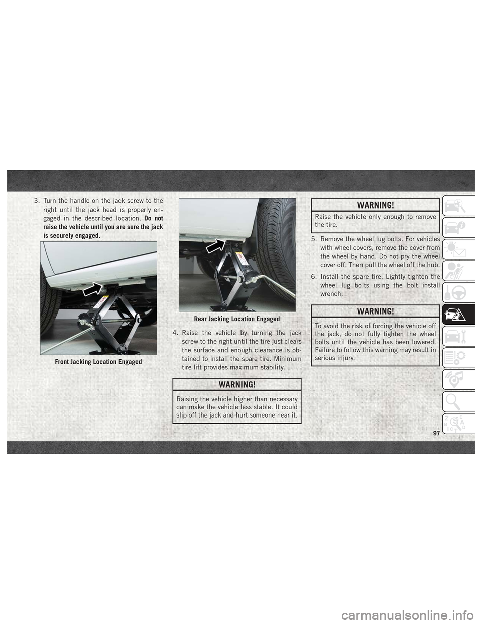
3. Turn the handle on the jack screw to theright until the jack head is properly en-
gaged in the described location. Do not
raise the vehicle until you are sure the jack
is securely engaged.
4. Raise the vehicle by turning the jackscrew to the right until the tire just clears
the surface and enough clearance is ob-
tained to install the spare tire. Minimum
tire lift provides maximum stability.
WARNING!
Raising the vehicle higher than necessary
can make the vehicle less stable. It could
slip off the jack and hurt someone near it.
WARNING!
Raise the vehicle only enough to remove
the tire.
5. Remove the wheel lug bolts. For vehicles with wheel covers, remove the cover from
the wheel by hand. Do not pry the wheel
cover off. Then pull the wheel off the hub.
6. Install the spare tire. Lightly tighten the wheel lug bolts using the bolt install
wrench.
WARNING!
To avoid the risk of forcing the vehicle off
the jack, do not fully tighten the wheel
bolts until the vehicle has been lowered.
Failure to follow this warning may result in
serious injury.
Front Jacking Location Engaged
Rear Jacking Location Engaged
97