charging Ram ProMaster City 2018 User Guide
[x] Cancel search | Manufacturer: RAM, Model Year: 2018, Model line: ProMaster City, Model: Ram ProMaster City 2018Pages: 180, PDF Size: 7.52 MB
Page 28 of 180
INTERNAL EQUIPMENT
Power Outlets
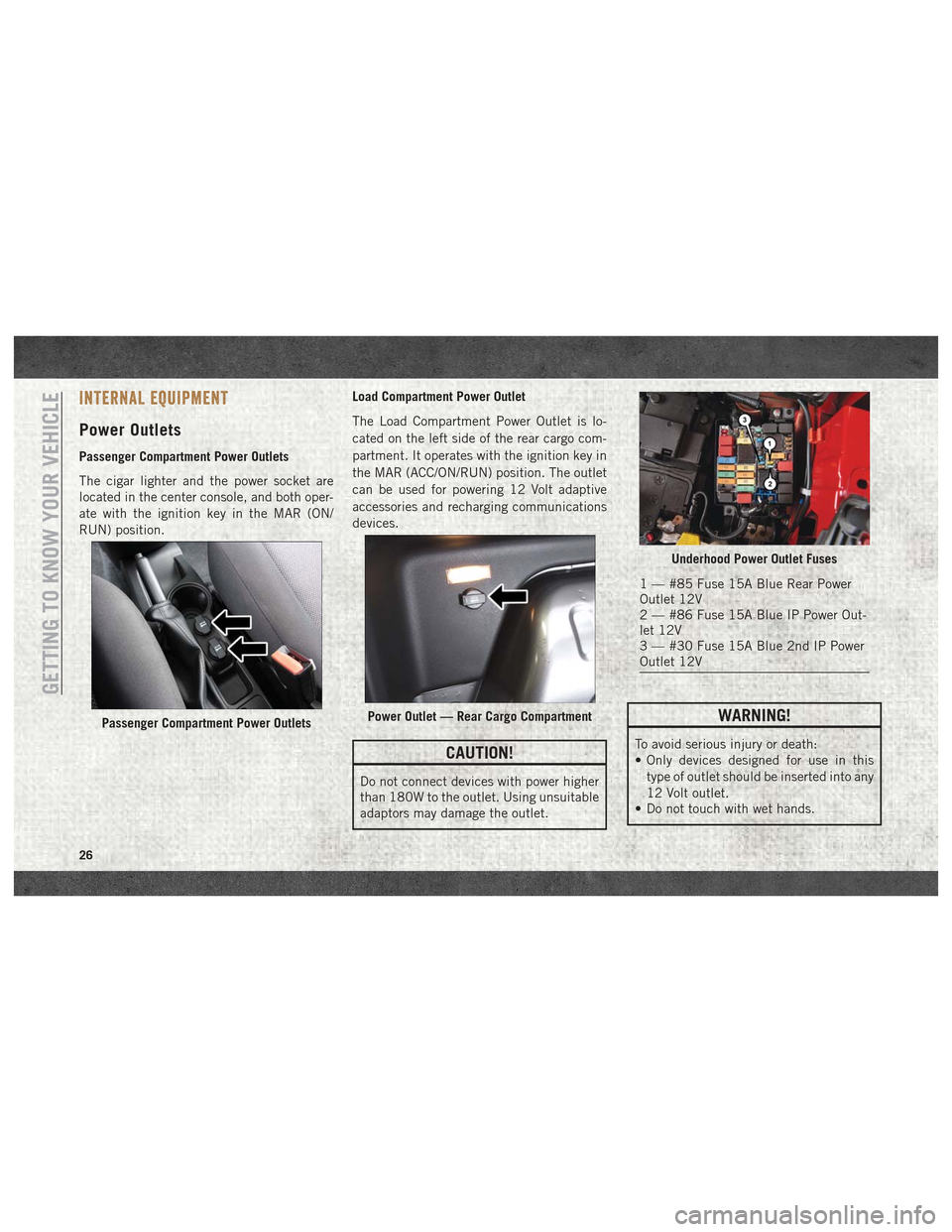
Passenger Compartment Power Outlets
The cigar lighter and the power socket are
located in the center console, and both oper-
ate with the ignition key in the MAR (ON/
RUN) position.Load Compartment Power Outlet
The Load Compartment Power Outlet is lo-
cated on the left side of the rear cargo com-
partment. It operates with the ignition key in
the MAR (ACC/ON/RUN) position. The outlet
can be used for powering 12 Volt adaptive
accessories and recharging communications
devices.
CAUTION!
Do not connect devices with power higher
than 180W to the outlet. Using unsuitable
adaptors may damage the outlet.
WARNING!
To avoid serious injury or death:
• Only devices designed for use in this
type of outlet should be inserted into any
12 Volt outlet.
• Do not touch with wet hands.
Passenger Compartment Power OutletsPower Outlet — Rear Cargo Compartment
Underhood Power Outlet Fuses
1 — #85 Fuse 15A Blue Rear Power
Outlet 12V
2 — #86 Fuse 15A Blue IP Power Out-
let 12V
3 — #30 Fuse 15A Blue 2nd IP Power
Outlet 12V
GETTING TO KNOW YOUR VEHICLE
26
Page 34 of 180
If the light remains on when the parking
brake has been disengaged, and the fluid
level is at the full mark on the master cylinder
reservoir, it indicates a possible brake hy-
draulic system malfunction or that a problem
with the Brake Booster has been detected by
the Anti-Lock Brake System (ABS) / Elec-
tronic Stability Control (ESC) system. In this
case, the light will remain on until the condi-
tion has been corrected. If the problem is
related to the brake booster, the ABS pump
will run when applying the brake, and a brake
pedal pulsation may be felt during each stop.
The dual brake system provides a reserve
braking capacity in the event of a failure to a
portion of the hydraulic system. A leak in
either half of the dual brake system is indi-
cated by the Brake Warning Light, which will
turn on when the brake fluid level in the
master cylinder has dropped below a speci-
fied level.
The light will remain on until the cause is
corrected.NOTE:
The light may flash momentarily during sharp
cornering maneuvers, which change fluid
level conditions. The vehicle should have
service performed, and the brake fluid level
checked.
If brake failure is indicated, immediate repair
is necessary.
WARNING!
Driving a vehicle with the red brake light
on is dangerous. Part of the brake system
may have failed. It will take longer to stop
the vehicle. You could have a collision.
Have the vehicle checked immediately.
Vehicles equipped with the Anti-Lock Brake
System (ABS) are also equipped with Elec-
tronic Brake Force Distribution (EBD). In the
event of an EBD failure, the Brake Warning
Light will turn on along with the ABS Light.
Immediate repair to the ABS system is re-
quired.
Operation of the Brake Warning Light can be
checked by turning the ignition switch from
the OFF position to the ON/RUN position. The light should illuminate for approximately
two seconds. The light should then turn off
unless the parking brake is applied or a brake
fault is detected. If the light does not illumi-
nate, have the light inspected by your autho-
rized dealer.
The light also will turn on when the parking
brake is applied with the ignition switch in
the ON/RUN position.
NOTE:
This light shows only that the parking brake is
applied. It does not show the degree of brake
application.
— Battery Charge Warning Light
This light illuminates when the battery is not
charging properly. If it stays on while the
engine is running, there may be a malfunc-
tion with the charging system. Contact your
authorized dealer as soon as possible.
This indicates a possible problem with the
electrical system or a related component.
— Door Open Warning Light
This indicator will illuminate when one or
more door(s) are not fully closed.
GETTING TO KNOW YOUR INSTRUMENT PANEL
32
Page 105 of 180
WARNING!
• Take care to avoid the radiator coolingfan whenever the hood is raised. It can
start anytime the ignition switch is ON.
You can be injured by moving fan blades.
WARNING!
• Remove any metal jewelry such as rings,watch bands and bracelets that could
make an inadvertent electrical contact.
You could be seriously injured.
• Batteries contain sulfuric acid that can
burn your skin or eyes and generate
hydrogen gas which is flammable and
explosive. Keep open flames or sparks
away from the battery.
1. Apply the parking brake, shift the auto- matic transmission into PARK and turn
the ignition to LOCK.
2. Turn off the heater, radio, and all unnec- essary electrical accessories.
3. If using another vehicle to jump-start the battery, park the vehicle within the jumper
cables reach, set the parking brake and
make sure the ignition is OFF.
WARNING!
Do not allow vehicles to touch each other
as this could establish a ground connec-
tion and personal injury could result.
Jump Starting Procedure
WARNING!
Failure to follow this jump starting proce-
dure could result in personal injury or
property damage due to battery explosion.
CAUTION!
Failure to follow these procedures could
result in damage to the charging system of
the booster vehicle or the discharged ve-
hicle.
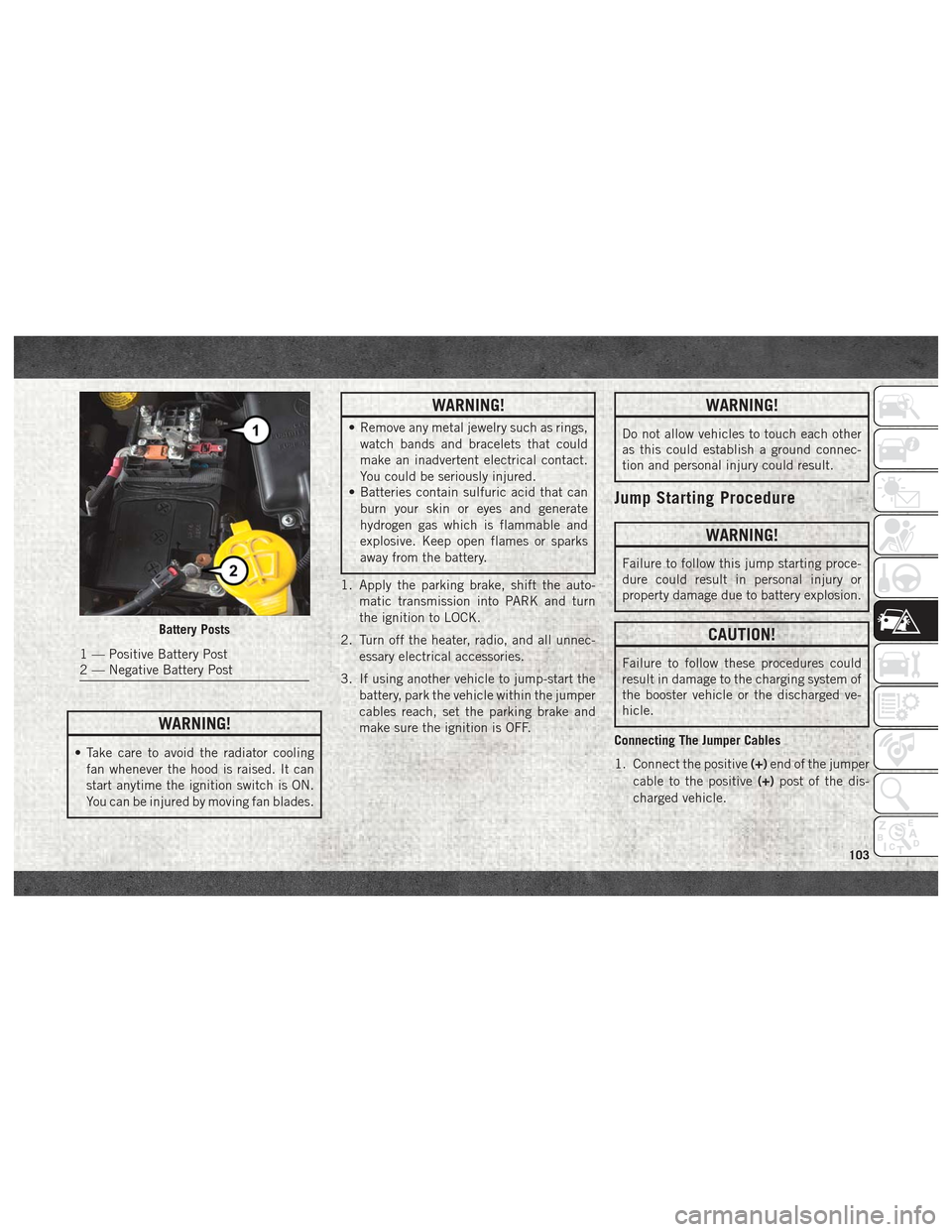
Connecting The Jumper Cables
1. Connect the positive (+)end of the jumper
cable to the positive (+)post of the dis-
charged vehicle.
Battery Posts
1 — Positive Battery Post
2 — Negative Battery Post
103
Page 106 of 180
2. Connect the opposite end of the positive(+) jumper cable to the positive (+)post of
the booster battery.
3. Connect the negative (-)end of the jumper
cable to the negative (-)post of the
booster battery.
4. Connect the opposite end of the negative (-)jumper cable to a good engine ground
(exposed metal part of the discharged
vehicle’s engine) away from the battery
and the fuel injection system.
WARNING!
Do not connect the jumper cable to the
negative (-) post of the discharged battery.
The resulting electrical spark could cause
the battery to explode and could result in
personal injury. Only use the specific
ground point, do not use any other exposed
metal parts.
5. Start the engine in the vehicle that has the booster battery, let the engine idle a
few minutes, and then start the engine in
the vehicle with the discharged battery. 6. Once the engine is started, remove the
jumper cables in the reverse sequence:
Disconnecting The Jumper Cables
1. Disconnect the negative (-)end of the
jumper cable from the engine ground of
the vehicle with the discharged battery.
2. Disconnect the opposite end of the nega- tive (-)jumper cable from the negative (-)
post of the booster battery.
3. Disconnect the positive (+)end of the
jumper cable from the positive (+)post of
the booster battery.
4. Disconnect the opposite end of the posi- tive (+)jumper cable from the positive (+)
post of the vehicle with the discharged
battery.
If frequent jump-starting is required to start
your vehicle you should have the battery and
charging system inspected at an authorized
dealer.
CAUTION!
Accessories plugged into the vehicle
power outlets draw power from the vehi-
cle’s battery, even when not in use (i.e.,
cellular devices, etc.). Eventually, if
plugged in long enough without engine
operation, the vehicle’s battery will dis-
charge sufficiently to degrade battery life
and/or prevent the engine from starting.
IGNITION KEY REMOVAL OVERRIDE
This vehicle is equipped with a Key Ignition
Park Interlock which requires the transmis-
sion to be in PARK before the ignition switch
can be turned to the LOCK/OFF (key removal)
position. To remove the key manually, pro-
ceed as follows:
1. Firmly apply the parking brake.
2. Remove the Allen Key located in the rear cargo area, in the tool bag (if equipped) or
on the left side in the cargo box.
3. Unlock the steering column, pull the tilt/ telescoping control handle down.IN CASE OF EMERGENCY
104
Page 169 of 180
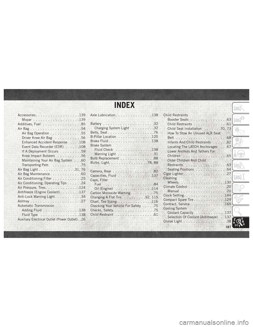
Accessories..................139
Mopar ...................139
Additives, Fuel ................85
AirBag .....................54 Air Bag Operation .............55
Driver Knee Air Bag ...........56
Enhanced Accident Response . . . .108
Event Data Recorder (EDR) ......108
If A Deployment Occurs .........59
Knee Impact Bolsters ..........56
Maintaining Your Air Bag System . . .60
Transporting Pets ............75
Air Bag Light ...............31, 76
Air Bag Maintenance .............60
Air Conditioning Filter ............25
Air Conditioning, Operating Tips ......24
Air Pressure, Tires ..............124
Antifreeze (Engine Coolant) ........137
Anti-Lock Warning Light ...........34
Ashtray .....................27
Automatic Transmission Adding Fluid ..............138
Fluid Type ................138
Auxiliary Electrical Outlet (Power Outlet). .26Axle Lubrication
...............138
Battery .....................32
Charging System Light .........32
Belts, Seat ...................76
B-Pillar Location ..............120
Brake Fluid ..................138
Brake System Fluid Check ...............138
Warning Light ...............31
Bulb Replacement ..............88
Bulbs, Light ................78, 88
Camera, Rear .................82
Capacities, Fluid ..............137
Caps, Filler Fuel ....................84
Oil (Engine) ...............114
Carbon Monoxide Warning ..........75
Changing A Flat Tire ..........92, 115
Chart, Tire Sizing ..............116
Checking Your Vehicle For Safety .....75
Checks, Safety .................75
Child Restraint ................61 Child Restraints
Booster Seats ...............63
Child Restraints ..............61
Child Seat Installation .......70, 73
How To Stow An Unused ALR Seat
Belt .....................68
Infants And Child Restraints ......62
Locating The LATCH Anchorages . . .67
Lower Anchors And Tethers For
Children ..................65
Older Children And Child
Restraints .................63
Seating Positions .............64
Cigar Lighter ..................27
Cleaning Wheels ..................130
Climate Control ................20
Manual ...................20
Clock Setting .................144
Compact Spare Tire .............129
Contract, Service ..............165
Cooling System Coolant Capacity ............137
Selection Of Coolant (Antifreeze) . .137
Cruise Light ..................38
INDEX
167