warning lights Ram ProMaster City 2018 User Guide
[x] Cancel search | Manufacturer: RAM, Model Year: 2018, Model line: ProMaster City, Model: Ram ProMaster City 2018Pages: 180, PDF Size: 7.52 MB
Page 13 of 180
Passenger Vehicle
Push and release the unlock button on key
fob to unlock all doors. Push and release the
Cargo unlock button on key fob to unlock the
cargo doors. The turn signal lights will flash
to acknowledge the unlock signal.
To Lock The Doors
Push and release the lock button on the key
fob to lock all doors. The turn signal lights
will flash to acknowledge the signal; the horn
will chirp too during turn signal lights flash-
ing.
If a door is open, the turn signal lights will
flash at an increased rate, and there will be
no horn chirp. This is to indicate that a door is
still open.
Locking Doors With A Key
1. Insert the key with either side up.
2. Turn the key to the right to lock the door.
3. Turn the key to the left to unlock the door.For maintenance procedures, refer to
“Dealer Service” in “Servicing And Mainte-
nance” in the Owner’s Manual at
www.mopar.com/en-us/care/owners-manual.html
(U.S. Residents) or www.owners.mopar.ca
(Canadian Residents).
General Information
The following regulatory statement applies to
all radio frequency (RF) devices equipped in
this vehicle:
This device complies with Part 15 of the FCC
Rules and with Industry Canada license-
exempt RSS standard(s). Operation is sub-
ject to the following two conditions:
1. This device may not cause harmful inter-
ference, and
2. This device must accept any interference received, including interference that may
cause undesired operation.
NOTE:
Changes or modifications not expressly ap-
proved by the party responsible for compli-
ance could void the user’s authority to oper-
ate the equipment.
SEATS
Seats are a part of the Occupant Restraint
System of the vehicle.
WARNING!
• It is dangerous to ride in a cargo area, inside or outside of a vehicle. In a colli-
sion, people riding in these areas are
more likely to be seriously injured or
killed.
• Do not allow people to ride in any area of
your vehicle that is not equipped with
seats and seat belts. In a collision,
people riding in these areas are more
likely to be seriously injured or killed.
• Be sure everyone in your vehicle is in a
seat and using a seat belt properly.
Heated Seats — If Equipped
On some models, the front driver and passen-
ger seats may be equipped with heaters in
both the seat cushions and seatbacks. The
controls for the front heated seats are located
on the lower outboard side of the seat.
11
Page 18 of 180
WARNING!
• A loose head restraint thrown forward ina collision or hard stop could cause
serious injury or death to occupants of
the vehicle. Always securely stow re-
moved head restraints in a location out-
side the occupant compartment.
• ALL the head restraints MUST be rein-
stalled in the vehicle to properly protect
the occupants. Follow the re-installation
instructions above prior to operating the
vehicle or occupying a seat.
STEERING WHEEL
Tilt/Telescoping Steering Column
This feature allows you to tilt the steering
column upward or downward. It also allows
you to lengthen or shorten the steering col-
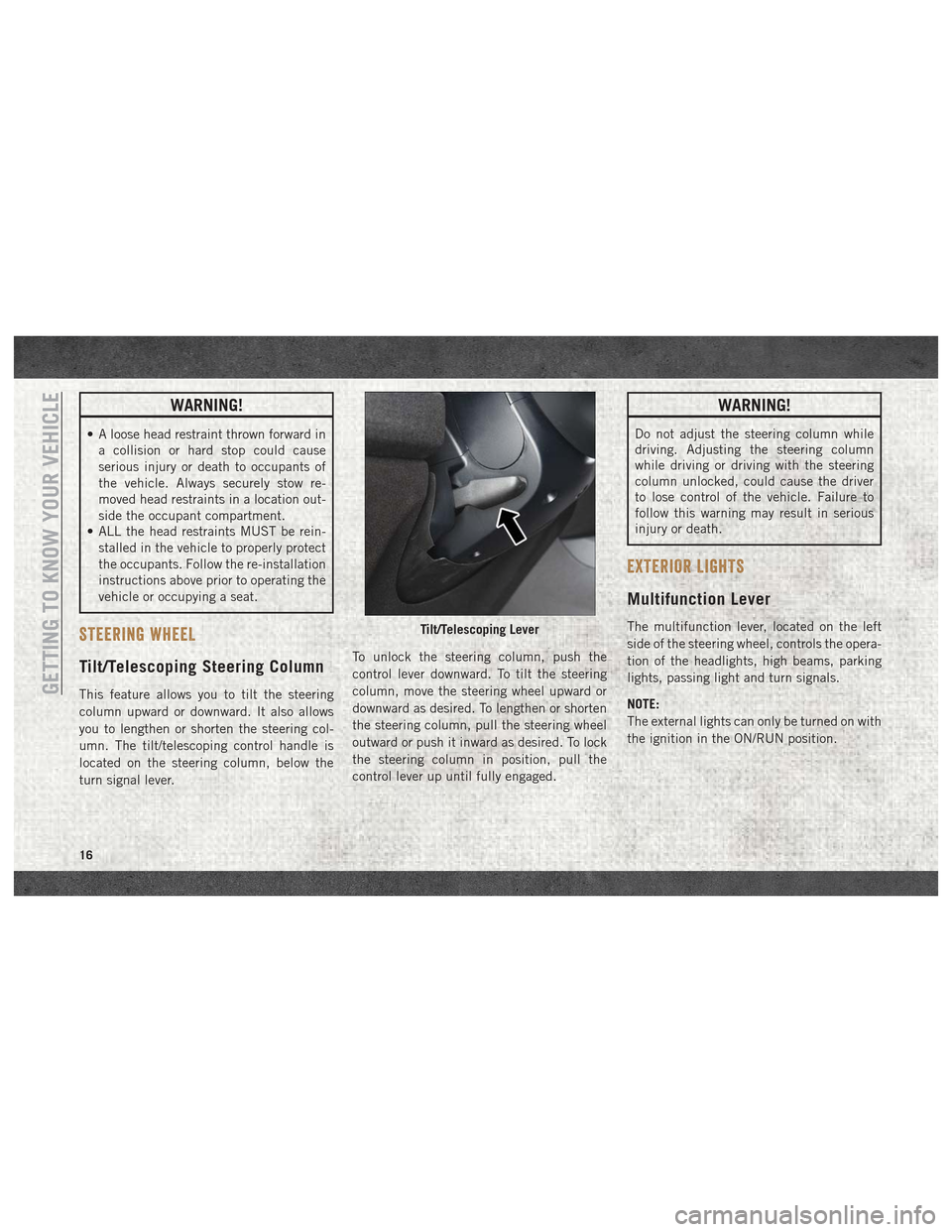
umn. The tilt/telescoping control handle is
located on the steering column, below the
turn signal lever. To unlock the steering column, push the
control lever downward. To tilt the steering
column, move the steering wheel upward or
downward as desired. To lengthen or shorten
the steering column, pull the steering wheel
outward or push it inward as desired. To lock
the steering column in position, pull the
control lever up until fully engaged.
WARNING!
Do not adjust the steering column while
driving. Adjusting the steering column
while driving or driving with the steering
column unlocked, could cause the driver
to lose control of the vehicle. Failure to
follow this warning may result in serious
injury or death.
EXTERIOR LIGHTS
Multifunction Lever
The multifunction lever, located on the left
side of the steering wheel, controls the opera-
tion of the headlights, high beams, parking
lights, passing light and turn signals.
NOTE:
The external lights can only be turned on with
the ignition in the ON/RUN position.Tilt/Telescoping Lever
GETTING TO KNOW YOUR VEHICLE
16
Page 29 of 180
WARNING!
• Close the lid when not in use and whiledriving the vehicle.
• If this outlet is mishandled, it may cause
an electric shock and failure.
CAUTION!
• Many accessories that can be plugged indraw power from the vehicle's battery,
even when not in use (i.e., cellular
phones, etc.). Eventually, if plugged in
long enough, the vehicle's battery will
discharge sufficiently to degrade battery
life and/or prevent the engine from start-
ing.
• Accessories that draw higher power (i.e.,
coolers, vacuum cleaners, lights, etc.)
CAUTION!
will degrade the battery even more
quickly. Only use these intermittently
and with greater caution.
• After the use of high power draw acces-
sories, or long periods of the vehicle not
being started (with accessories still
plugged in), the vehicle must be driven a
sufficient length of time to allow the
generator to recharge the vehicle's bat-
tery.
Cigar Lighter And Ash Receiver —
If Equipped
A removable ash receiver and cigar lighter are
available. Push the cigar lighter button to activate the
cigar lighter when the ignition key is in the
MAR (ON/RUN) position.
After a few seconds the button returns to its
initial position and the cigar lighter is ready
for use.
NOTE:
Always check that the cigar lighter has turned
itself off.
WARNING!
The cigar lighter becomes very hot. Handle
it carefully and make sure children don’t
touch it: risk of fire and/or burning.
27
Page 31 of 180
GETTING TO KNOW YOUR INSTRUMENT PANEL
INSTRUMENT CLUSTER DISPLAY.....30
Location And Controls............30
WARNING LIGHTS AND MESSAGES ....31
Red Warning Lights..............31 Yellow Warning Lights
............34
Yellow Indicator Lights ............37
Green Indicator Lights ............37
Blue Indicator Lights .............38
ONBOARD DIAGNOSTIC SYSTEM —
OBDII .....................38
Onboard Diagnostic System (OBD II)
Cybersecurity.................38
GETTING TO KNOW YOUR INSTRUMENT PANEL
29
Page 32 of 180
INSTRUMENT CLUSTER DISPLAY
Your vehicle may be equipped with an instru-
ment cluster display, which offers useful in-
formation to the driver. With the ignition in
the STOP/OFF mode, opening/closing of a
door will activate the display for viewing, and
display the total miles, or kilometers, in the
odometer. Your instrument cluster display is
designed to display important information
about your vehicle’s systems and features.
Using a driver interactive display located on
the instrument panel, your instrument clus-
ter display can show you how systems are
working and give you warnings when they are
not. The steering wheel mounted controls
allow you to scroll through the main menus
and submenus. You can access the specific
information you want and make selections
and adjustments.
Location And Controls
The instrument cluster display features a
driver-interactive display that is located in
the instrument cluster.The menu items described below are an ex-
ample of what can be found in the vehicle's
menu:
• Dimmer
• Speed Beep
• Trip B
• Set Time
• Set Date
• Autoclose
• Units
• Language
• Buzzer Volume
• Belt Buzzer
• Day Lights
The system allows the driver to select infor-
mation by pushing the following buttons
mounted on the instrument panel to the right
of the steering column:
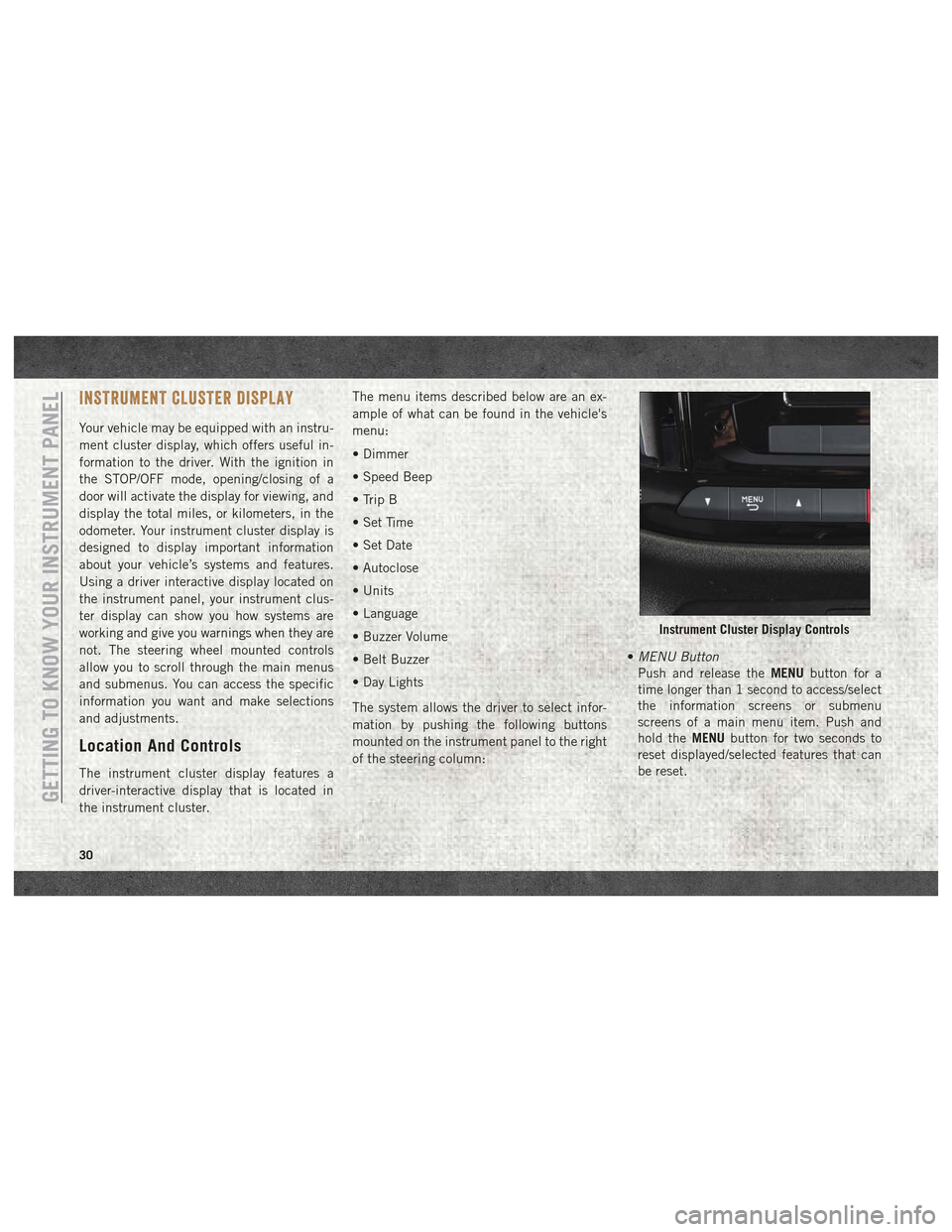
•
MENU Button
Push and release the MENUbutton for a
time longer than 1 second to access/select
the information screens or submenu
screens of a main menu item. Push and
hold the MENUbutton for two seconds to
reset displayed/selected features that can
be reset.
Instrument Cluster Display Controls
GETTING TO KNOW YOUR INSTRUMENT PANEL
30
Page 33 of 180
•UP Arrow Button
Push and release the uparrow button to
scroll upward through the main menu and
submenus.
• DOWN Arrow Button
Push and release the downarrow button to
scroll downward through the main menu
and submenus.
NOTE:
If equipped with a Uconnect system, some of
the menu items will be present in the radio
head unit. Refer to “Uconnect Settings” in
“Multimedia” in the Owner’s Manual at
www.mopar.com/en-us/care/owners-manual.html
(U.S. Residents) or www.owners.mopar.ca
(Canadian Residents) for further information.
Dimmer:
With headlights on and without entering in
the menu, push the upordown arrow button
to increase or decrease the brightness of the
instrument panel, graphics and command
buttons. Selecting An Option Of The Main Menu With
Submenu:
1. Briefly push and release the
MENUbutton
to display the first submenu option.
2. Push and release the upordown arrow
button (by single pushes) to scroll through
all the submenu options.
3. Briefly push and release the MENUbutton
to select the displayed submenu option
and to open the relevant setup menu.
4. Push and release the upordown arrow
button (by single pushes) to select the
new setting for this submenu option.
5. Briefly push and release the MENUbutton
to store the new setting and go back to the
previously selected submenu option.
6. Push and hold the MENUbutton to return
to the main menu (short hold) or the main
screen (longer hold).
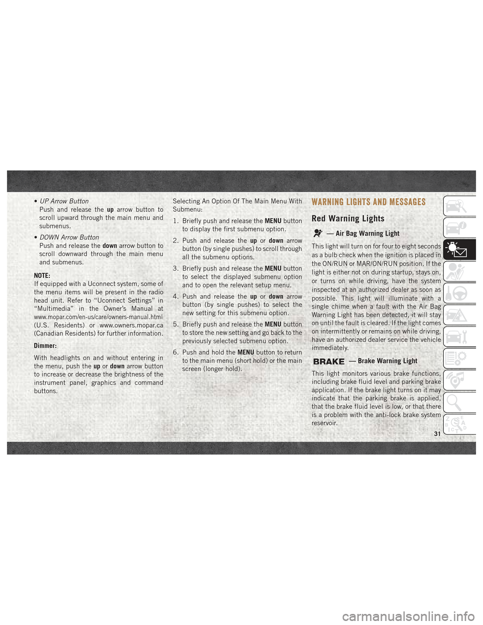
WARNING LIGHTS AND MESSAGES
Red Warning Lights
— Air Bag Warning Light
This light will turn on for four to eight seconds
as a bulb check when the ignition is placed in
the ON/RUN or MAR/ON/RUN position. If the
light is either not on during startup, stays on,
or turns on while driving, have the system
inspected at an authorized dealer as soon as
possible. This light will illuminate with a
single chime when a fault with the Air Bag
Warning Light has been detected, it will stay
on until the fault is cleared. If the light comes
on intermittently or remains on while driving,
have an authorized dealer service the vehicle
immediately.
— Brake Warning Light
This light monitors various brake functions,
including brake fluid level and parking brake
application. If the brake light turns on it may
indicate that the parking brake is applied,
that the brake fluid level is low, or that there
is a problem with the anti-lock brake system
reservoir.
31
Page 36 of 180
WARNING!
Light is illuminated you could cause the
fluid to boil over, come in contact with hot
engine or exhaust components and cause a
fire.
CAUTION!
Continuous driving with the Transmission
Temperature Warning Light illuminated
will eventually cause severe transmission
damage or transmission failure.
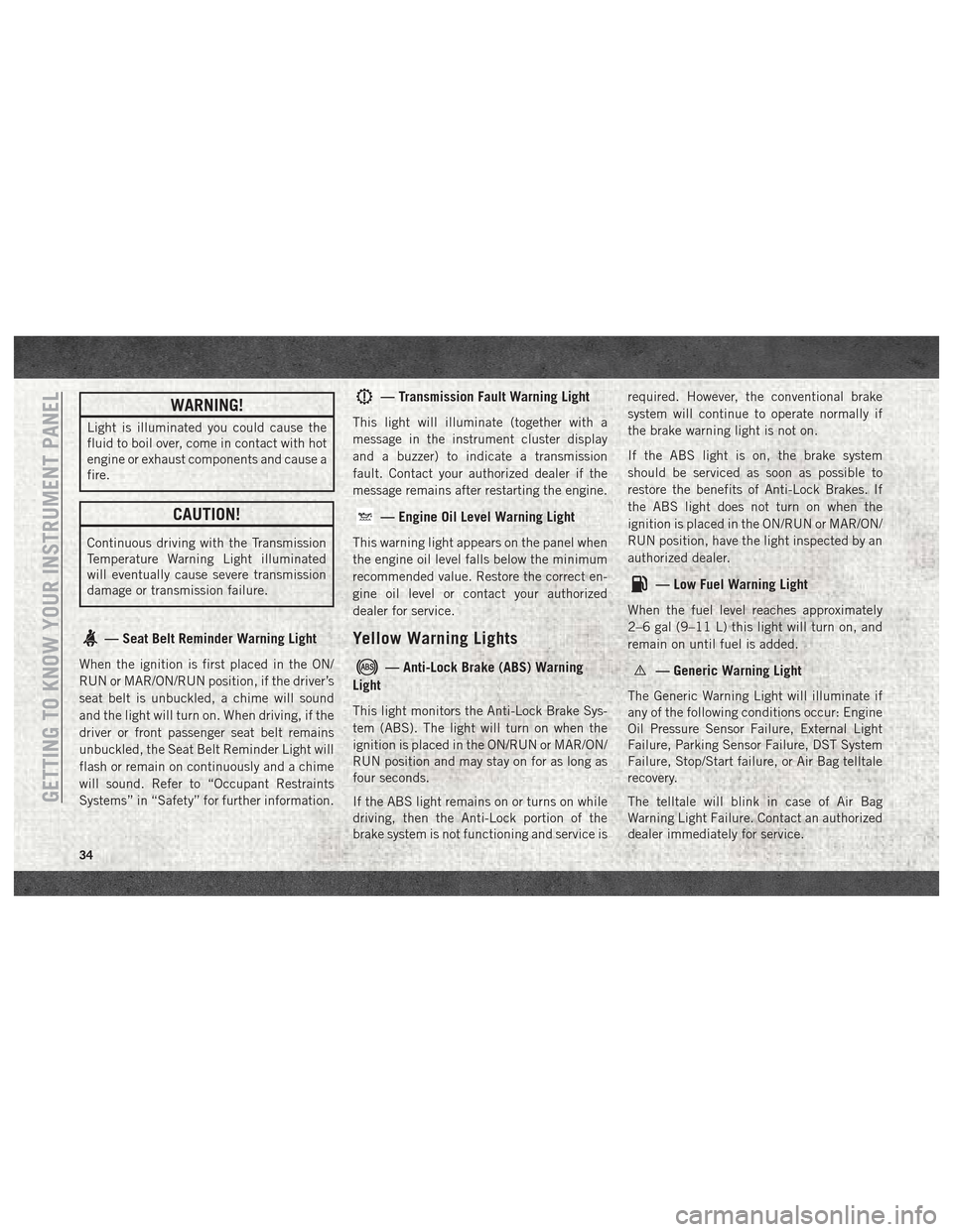
— Seat Belt Reminder Warning Light
When the ignition is first placed in the ON/
RUN or MAR/ON/RUN position, if the driver’s
seat belt is unbuckled, a chime will sound
and the light will turn on. When driving, if the
driver or front passenger seat belt remains
unbuckled, the Seat Belt Reminder Light will
flash or remain on continuously and a chime
will sound. Refer to “Occupant Restraints
Systems” in “Safety” for further information.
— Transmission Fault Warning Light
This light will illuminate (together with a
message in the instrument cluster display
and a buzzer) to indicate a transmission
fault. Contact your authorized dealer if the
message remains after restarting the engine.
— Engine Oil Level Warning Light
This warning light appears on the panel when
the engine oil level falls below the minimum
recommended value. Restore the correct en-
gine oil level or contact your authorized
dealer for service.
Yellow Warning Lights
— Anti-Lock Brake (ABS) Warning
Light
This light monitors the Anti-Lock Brake Sys-
tem (ABS). The light will turn on when the
ignition is placed in the ON/RUN or MAR/ON/
RUN position and may stay on for as long as
four seconds.
If the ABS light remains on or turns on while
driving, then the Anti-Lock portion of the
brake system is not functioning and service is required. However, the conventional brake
system will continue to operate normally if
the brake warning light is not on.
If the ABS light is on, the brake system
should be serviced as soon as possible to
restore the benefits of Anti-Lock Brakes. If
the ABS light does not turn on when the
ignition is placed in the ON/RUN or MAR/ON/
RUN position, have the light inspected by an
authorized dealer.
— Low Fuel Warning Light
When the fuel level reaches approximately
2–6 gal (9–11 L) this light will turn on, and
remain on until fuel is added.
— Generic Warning Light
The Generic Warning Light will illuminate if
any of the following conditions occur: Engine
Oil Pressure Sensor Failure, External Light
Failure, Parking Sensor Failure, DST System
Failure, Stop/Start failure, or Air Bag telltale
recovery.
The telltale will blink in case of Air Bag
Warning Light Failure. Contact an authorized
dealer immediately for service.
GETTING TO KNOW YOUR INSTRUMENT PANEL
34
Page 39 of 180
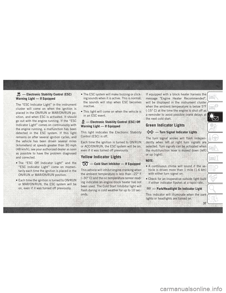
— Electronic Stability Control (ESC)
Warning Light — If Equipped
The “ESC Indicator Light” in the instrument
cluster will come on when the ignition is
placed in the ON/RUN or MAR/ON/RUN po-
sition, and when ESC is activated. It should
go out with the engine running. If the “ESC
Indicator Light” comes on continuously with
the engine running, a malfunction has been
detected in the ESC system. If this light
remains on after several ignition cycles, and
the vehicle has been driven several miles
(kilometers) at speeds greater than 30 mph
(48 km/h), see your authorized dealer as soon
as possible to have the problem diagnosed
and corrected.
• The “ESC Off Indicator Light” and the “ESC Indicator Light” come on momen-
tarily each time the ignition is placed in the
ON/RUN or MAR/ON/RUN position.
• Each time the ignition is turned to ON/RUN or MAR/ON/RUN, the ESC system will be
on, even if it was turned off previously. • The ESC system will make buzzing or click-
ing sounds when it is active. This is normal;
the sounds will stop when ESC becomes
inactive.
• This light will come on when the vehicle is in an ESC event.
— Electronic Stability Control (ESC) Off
Warning Light — If Equipped
This light indicates the Electronic Stability
Control (ESC) is off.
Each time the ignition is turned to ON/RUN
or ACC/ON/RUN, the ESC system will be on,
even if it was turned off previously.
Yellow Indicator Lights
— Cold Start Inhibitor — If Equipped
This vehicle will inhibit engine cranking when
the ambient temperature is less than –22° F
(–30° C) and the oil temperature sensor read-
ing indicates an engine block heater has not
been used. The Cold Start Inhibitor light will
flash during in cold weather for up to 10 sec-
onds. If equipped with a block heater harness the
message "Engine Heater Recommended",
will be displayed in the instrument cluster
when the ambient temperature is below 5°F
(-15° C) at the time the engine is shut off as
a reminder to avoid possible crank delays at
the next cold start.
Green Indicator Lights
— Turn Signal Indicator Lights
The turn signal arrows will flash indepen-
dently when left or right turn signals are
selected. Turn signals can be activated when
the multifunction lever is moved down (left)
or up (right).
NOTE:
• A continuous chime will sound if the ve-
hicle is driven more than 1 mile (1.6 km)
with either turn signal on.
• Check for an inoperative outside light bulb if either indicator flashes at a rapid rate.
— Park/Headlight On Indicator Light
This indicator will illuminate when the park
lights or headlights are turned on.
37
Page 40 of 180
— Front Fog Indicator Light — If
Equipped
This indicator will illuminate when the front
fog lights are on.
— Cruise Control SET Indicator Light
This light will turn on when the speed control
is set to the desired speed. Refer to “Speed
Control” in “Starting And Operating” for fur-
ther information.
Blue Indicator Lights
— High Beam Indicator Light
This indicator shows that the high beam
headlights are on. With the low beams acti-
vated, push the multifunction lever forward
(toward the front of the vehicle) to turn on the
high beams. Pull the multifunction lever rear-
ward (toward the rear of the vehicle) to turn
off the high beams. Pull the lever toward you
for a temporary high beam on, "flash to pass"
scenario.
ONBOARD DIAGNOSTIC SYSTEM —
OBD II
Your vehicle is equipped with a sophisticated
Onboard Diagnostic system called OBD II.
This system monitors the performance of the
emissions, engine, and transmission control
systems. When these systems are operating
properly, your vehicle will provide excellent
performance and fuel economy, as well as
engine emissions well within current govern-
ment regulations.
If any of these systems require service, the
OBD II system will turn on the Malfunction
Indicator Light (MIL). It will also store diag-
nostic codes and other information to assist
your service technician in making repairs.
Although your vehicle will usually be drivable
and not need towing, see your authorized
dealer for service as soon as possible.
CAUTION!
• Prolonged driving with the MIL on could cause further damage to the emission
control system. It could also affect fuel
CAUTION!
economy and driveability. The vehicle
must be serviced before any emissions
tests can be performed.
• If the MIL is flashing while the vehicle is
running, severe catalytic converter dam-
age and power loss will soon occur. Im-
mediate service is required.
Onboard Diagnostic System (OBD
II) Cybersecurity
Your vehicle is required to have an Onboard
Diagnostic system (OBD II) and a connection
port to allow access to information related to
the performance of your emissions controls.
Authorized service technicians may need to
access this information to assist with the
diagnosis and service of your vehicle and
emissions system.
WARNING!
• ONLY an authorized service technicianshould connect equipment to the OBD IIGETTING TO KNOW YOUR INSTRUMENT PANEL
38
Page 58 of 180
Knee Impact Bolsters
The Knee Impact Bolsters help protect the
knees of the driver and front passenger, and
position the front occupants for improved
interaction with the front air bags.
WARNING!
• Do not drill, cut, or tamper with the kneeimpact bolsters in any way.
• Do not mount any accessories to the
knee impact bolsters such as alarm
lights, stereos, citizen band radios, etc.
Supplemental Driver Knee Air Bag
This vehicle is equipped with a Supplemental
Driver Knee Air Bag mounted in the instru-
ment panel below the steering column. The
Supplemental Driver Knee Air Bag provides
enhanced protection during a frontal impact
by working together with the seat belts, pre-
tensioners, and front air bags.
Supplemental Side Air Bags
Supplemental Seat-Mounted Side Air Bags
(SABs)
This vehicle is equipped with Supplemental
Seat-Mounted Side Air Bags (SABs).
Supplemental Seat-Mounted Side Air Bags
(SABs) are located in the outboard side of the
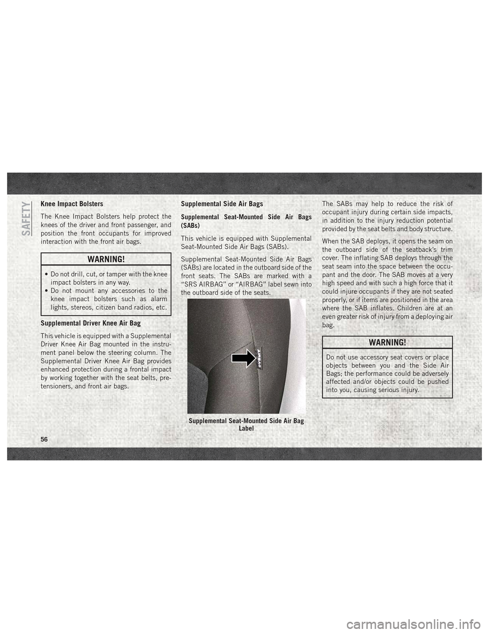
front seats. The SABs are marked with a
“SRS AIRBAG” or “AIRBAG” label sewn into
the outboard side of the seats. The SABs may help to reduce the risk of
occupant injury during certain side impacts,
in addition to the injury reduction potential
provided by the seat belts and body structure.
When the SAB deploys, it opens the seam on
the outboard side of the seatback’s trim
cover. The inflating SAB deploys through the
seat seam into the space between the occu-
pant and the door. The SAB moves at a very
high speed and with such a high force that it
could injure occupants if they are not seated
properly, or if items are positioned in the area
where the SAB inflates. Children are at an
even greater risk of injury from a deploying air
bag.
WARNING!
Do not use accessory seat covers or place
objects between you and the Side Air
Bags; the performance could be adversely
affected and/or objects could be pushed
into you, causing serious injury.
Supplemental Seat-Mounted Side Air Bag
Label
SAFETY
56