jump start Ram ProMaster City 2018 User Guide
[x] Cancel search | Manufacturer: RAM, Model Year: 2018, Model line: ProMaster City, Model: Ram ProMaster City 2018Pages: 180, PDF Size: 7.52 MB
Page 89 of 180
IN CASE OF EMERGENCY
BULB REPLACEMENT............88
Replacement Bulbs..............88
FUSES......................89
Underhood Fuses ...............89
Interior Fuses .................91
Central Unit Fuse Panel ...........92
JACKING AND TIRE CHANGING ......92
Jack Location.................93
Removing The Spare Tire ..........93
Preparations For Jacking ..........95Jacking Instructions
.............95
Vehicles With Alloy Wheels .........98
Vehicles Equipped With Wheel Covers. . .99
TIRE SERVICE KIT — IF EQUIPPED . .100
Tire Service Kit Storage ..........100
Tire Service Kit Usage ...........100
JUMP STARTING..............102
Preparations For Jump Starting ......102
Jump Starting Procedure ..........103
IGNITION KEY REMOVAL OVERRIDE . . .104 GEAR SELECTOR OVERRIDE
.......105
IF YOUR ENGINE OVERHEATS ......106
FREEING A STUCK VEHICLE .......106
TOWING A DISABLED VEHICLE .....108
ENHANCED ACCIDENT RESPONSE
SYSTEM (EARS) ...............108
EVENT DATA RECORDER (EDR) ......108
IN CASE OF EMERGENCY
87
Page 104 of 180
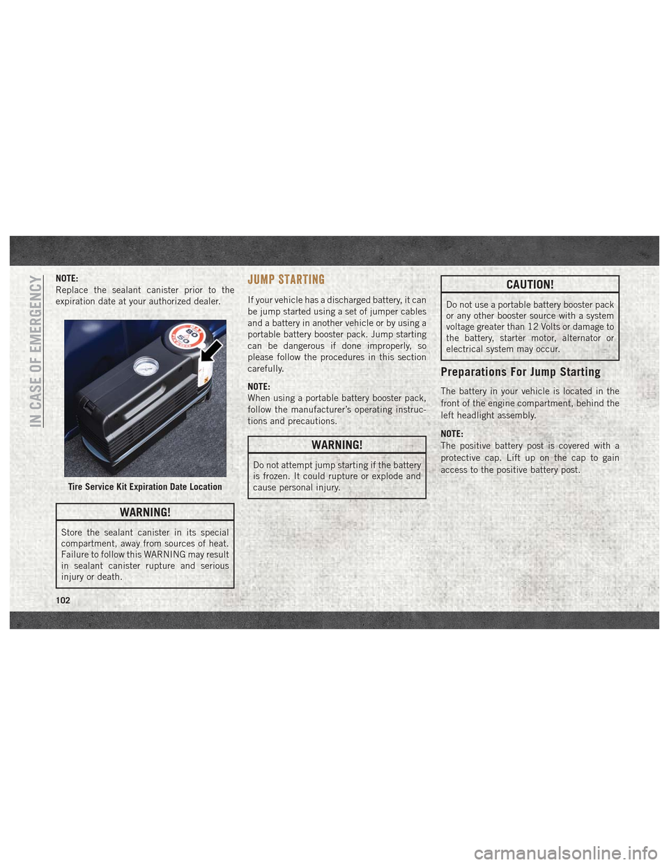
NOTE:
Replace the sealant canister prior to the
expiration date at your authorized dealer.
WARNING!
Store the sealant canister in its special
compartment, away from sources of heat.
Failure to follow this WARNING may result
in sealant canister rupture and serious
injury or death.
JUMP STARTING
If your vehicle has a discharged battery, it can
be jump started using a set of jumper cables
and a battery in another vehicle or by using a
portable battery booster pack. Jump starting
can be dangerous if done improperly, so
please follow the procedures in this section
carefully.
NOTE:
When using a portable battery booster pack,
follow the manufacturer’s operating instruc-
tions and precautions.
WARNING!
Do not attempt jump starting if the battery
is frozen. It could rupture or explode and
cause personal injury.
CAUTION!
Do not use a portable battery booster pack
or any other booster source with a system
voltage greater than 12 Volts or damage to
the battery, starter motor, alternator or
electrical system may occur.
Preparations For Jump Starting
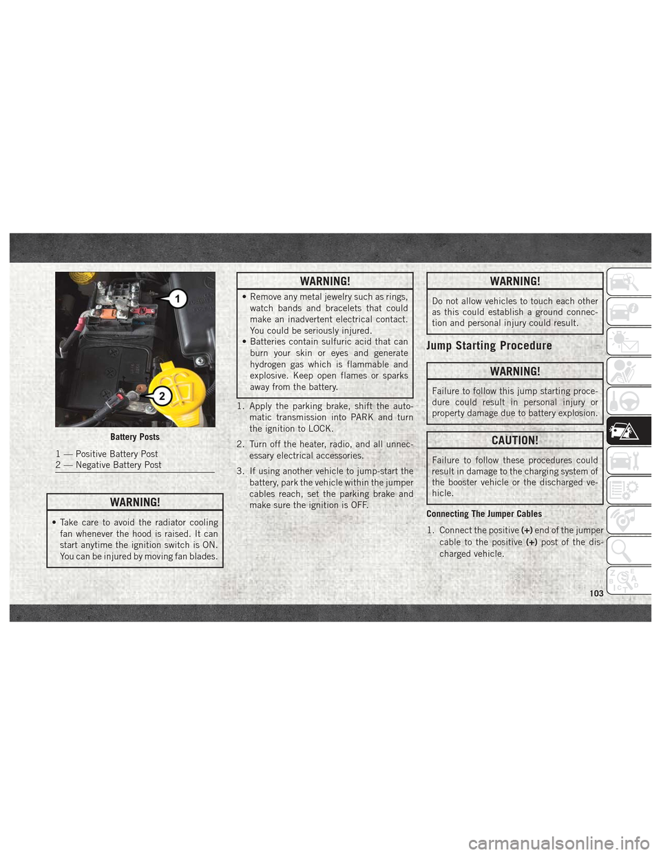
The battery in your vehicle is located in the
front of the engine compartment, behind the
left headlight assembly.
NOTE:
The positive battery post is covered with a
protective cap. Lift up on the cap to gain
access to the positive battery post.
Tire Service Kit Expiration Date Location
IN CASE OF EMERGENCY
102
Page 105 of 180
WARNING!
• Take care to avoid the radiator coolingfan whenever the hood is raised. It can
start anytime the ignition switch is ON.
You can be injured by moving fan blades.
WARNING!
• Remove any metal jewelry such as rings,watch bands and bracelets that could
make an inadvertent electrical contact.
You could be seriously injured.
• Batteries contain sulfuric acid that can
burn your skin or eyes and generate
hydrogen gas which is flammable and
explosive. Keep open flames or sparks
away from the battery.
1. Apply the parking brake, shift the auto- matic transmission into PARK and turn
the ignition to LOCK.
2. Turn off the heater, radio, and all unnec- essary electrical accessories.
3. If using another vehicle to jump-start the battery, park the vehicle within the jumper
cables reach, set the parking brake and
make sure the ignition is OFF.
WARNING!
Do not allow vehicles to touch each other
as this could establish a ground connec-
tion and personal injury could result.
Jump Starting Procedure
WARNING!
Failure to follow this jump starting proce-
dure could result in personal injury or
property damage due to battery explosion.
CAUTION!
Failure to follow these procedures could
result in damage to the charging system of
the booster vehicle or the discharged ve-
hicle.
Connecting The Jumper Cables
1. Connect the positive (+)end of the jumper
cable to the positive (+)post of the dis-
charged vehicle.
Battery Posts
1 — Positive Battery Post
2 — Negative Battery Post
103
Page 106 of 180
2. Connect the opposite end of the positive(+) jumper cable to the positive (+)post of
the booster battery.
3. Connect the negative (-)end of the jumper
cable to the negative (-)post of the
booster battery.
4. Connect the opposite end of the negative (-)jumper cable to a good engine ground
(exposed metal part of the discharged
vehicle’s engine) away from the battery
and the fuel injection system.
WARNING!
Do not connect the jumper cable to the
negative (-) post of the discharged battery.
The resulting electrical spark could cause
the battery to explode and could result in
personal injury. Only use the specific
ground point, do not use any other exposed
metal parts.
5. Start the engine in the vehicle that has the booster battery, let the engine idle a
few minutes, and then start the engine in
the vehicle with the discharged battery. 6. Once the engine is started, remove the
jumper cables in the reverse sequence:
Disconnecting The Jumper Cables
1. Disconnect the negative (-)end of the
jumper cable from the engine ground of
the vehicle with the discharged battery.
2. Disconnect the opposite end of the nega- tive (-)jumper cable from the negative (-)
post of the booster battery.
3. Disconnect the positive (+)end of the
jumper cable from the positive (+)post of
the booster battery.
4. Disconnect the opposite end of the posi- tive (+)jumper cable from the positive (+)
post of the vehicle with the discharged
battery.
If frequent jump-starting is required to start
your vehicle you should have the battery and
charging system inspected at an authorized
dealer.
CAUTION!
Accessories plugged into the vehicle
power outlets draw power from the vehi-
cle’s battery, even when not in use (i.e.,
cellular devices, etc.). Eventually, if
plugged in long enough without engine
operation, the vehicle’s battery will dis-
charge sufficiently to degrade battery life
and/or prevent the engine from starting.
IGNITION KEY REMOVAL OVERRIDE
This vehicle is equipped with a Key Ignition
Park Interlock which requires the transmis-
sion to be in PARK before the ignition switch
can be turned to the LOCK/OFF (key removal)
position. To remove the key manually, pro-
ceed as follows:
1. Firmly apply the parking brake.
2. Remove the Allen Key located in the rear cargo area, in the tool bag (if equipped) or
on the left side in the cargo box.
3. Unlock the steering column, pull the tilt/ telescoping control handle down.IN CASE OF EMERGENCY
104
Page 170 of 180
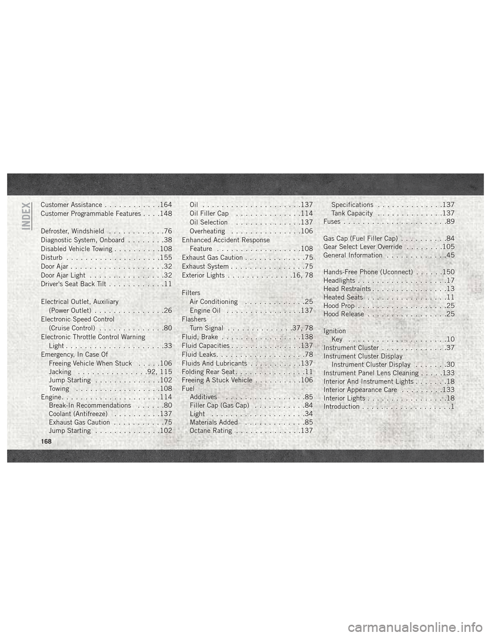
Customer Assistance............164
Customer Programmable Features . . . .148
Defroster, Windshield ............76
Diagnostic System, Onboard ........38
Disabled Vehicle Towing ..........108
Disturb ....................155
Door Ajar ....................32
Door Ajar Light ................32
Driver's Seat Back Tilt ............11
Electrical Outlet, Auxiliary (Power Outlet) ...............26
Electronic Speed Control (Cruise Control) ..............80
Electronic Throttle Control Warning Light .....................33
Emergency, In Case Of Freeing Vehicle When Stuck .....106
Jacking ...............92, 115
Jump Starting ..............102
Towing ..................108
Engine .....................114
Break-In Recommendations ......80
Coolant (Antifreeze) ..........137
Exhaust Gas Caution ...........75
Jump Starting ..............102 Oil .....................137
Oil Filler Cap
..............114
Oil Selection ..............137
Overheating ...............106
Enhanced Accident Response Feature ..................108
Exhaust Gas Caution .............75
Exhaust System ................75
Exterior Lights ..............16, 78
Filters Air Conditioning .............25
Engine Oil ................137
Flashers Turn Signal ..............37, 78
Fluid, Brake .................138
Fluid Capacities ...............137
Fluid Leaks ...................78
Fluids And Lubricants ...........137
Folding Rear Seat ...............11
Freeing A Stuck Vehicle ..........106
Fuel Additives .................
85
Filler Cap (Gas Cap) ...........84
Light ....................34
Materials Added .............85
Octane Rating ..............137 Specifications
..............137
Tank Capacity ..............137
Fuses ......................89
Gas Cap (Fuel Filler Cap) ..........84
Gear Select Lever Override ........105
General Information .............45
Hands-Free Phone (Uconnect) ......150
Headlights ...................17
Head Restraints ................13
Heated Seats .................11
Hood Prop ...................25
Hood Release .................25
Ignition Key .....................10
Instrument Cluster ..............37
Instrument Cluster Display Instrument Cluster Display .......30
Instrument Panel Lens Cleaning .....133
Interior And Instrument Lights .......18
Interior Appearance Care .........133
Interior Lights .................18
Introduction ...................1
INDEX
168
Page 171 of 180
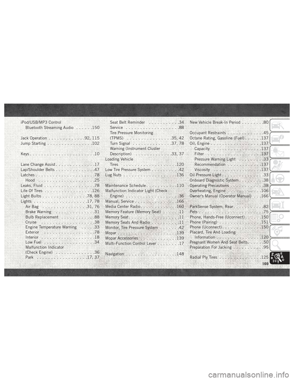
iPod/USB/MP3 ControlBluetooth Streaming Audio ......150
Jack Operation .............92, 115
Jump Starting ................102
Keys .......................10
Lane Change Assist ..............17
Lap/Shoulder Belts ..............47
Latches .....................78
Hood ....................25
Leaks, Fluid ..................78
Life Of Tires .................126
Light Bulbs ................78, 88
Lights ...................17, 78
AirBag ................31, 76
Brake Warning ..............31
Bulb Replacement ............88
Cruise ...................38
Engine Temperature Warning .....33
Exterior ..................78
Interior ...................18
Low Fuel ..................34
Malfunction Indicator
(Check Engine) ..............36
Park ..................17, 37 Seat Belt Reminder
...........34
Service ...................88
Tire Pressure Monitoring
(TPMS) ................35, 42
Turn Signal ..............37, 78
Warning (Instrument Cluster
Description) .............33, 37
Loading Vehicle Tires ...................120
Low Tire Pressure System ..........42
Lug Nuts ...................136
Maintenance Schedule ...........110
Malfunction Indicator Light (Check Engine) ...................36
Manual, Service ...............166
Media Center Radio .............160
Memory Feature (Memory Seat) ......11
Memory Seat ..................11
Memory Seats And Radio ..........11
Monitor, Tire Pressure System .......42
Mopar .....................139
Mopar Accessories .............139
Multi-Function Control Lever ........17
Navigation ..................148 New
Vehicle Break-In Period
........80
Occupant Restraints .............45
Octane Rating, Gasoline (Fuel) ......137
Oil, Engine ..................137
Capacity .................137
Filter ...................137
Pressure Warning Light .........33
Recommendation ............137
Viscosity .................137
Oil Pressure Light ...............33
Onboard Diagnostic System .........38
Operating Precautions ............38
Overheating, Engine ............106
Owner's Manual (Operator Manual) . . .166
ParkSense System, Rear ...........82
Pets .......................75
Phone, Hands-Free (Uconnect) ......150
Phone (Pairing) ...............151
Phone (Uconnect) ..............150
Placard, Tire And Loading Information ................120
Pregnant Women And Seat Belts ......50
Preparation For Jacking ...........95
Radial Ply Tires ...............125
169