lock Ram ProMaster City 2018 User Guide
[x] Cancel search | Manufacturer: RAM, Model Year: 2018, Model line: ProMaster City, Model: Ram ProMaster City 2018Pages: 180, PDF Size: 7.52 MB
Page 9 of 180
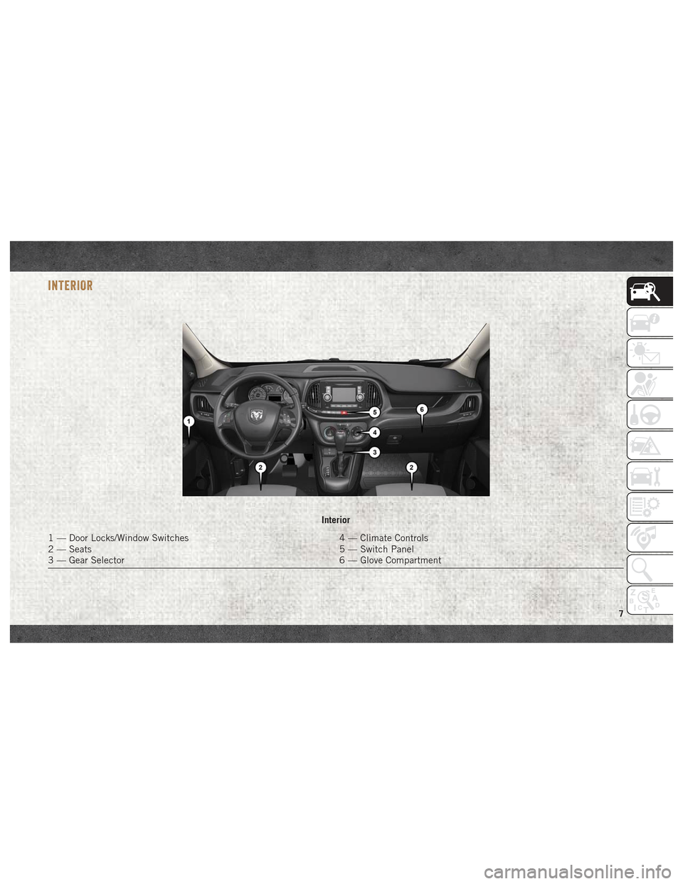
INTERIOR
Interior
1 — Door Locks/Window Switches4 — Climate Controls
2 — Seats 5 — Switch Panel
3 — Gear Selector 6 — Glove Compartment
7
Page 12 of 180
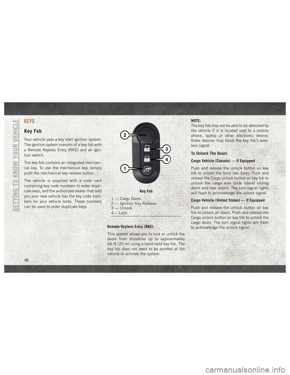
KEYS
Key Fob
Your vehicle uses a key start ignition system.
The ignition system consists of a key fob with
a Remote Keyless Entry (RKE) and an igni-
tion switch.
The key fob contains an integrated mechani-
cal key. To use the mechanical key, simply
push the mechanical key release button.
The vehicle is supplied with a code card
containing key code numbers to order dupli-
cate keys, and the authorized dealer that sold
you your new vehicle has the key code num-
bers for your vehicle locks. These numbers
can be used to order duplicate keys.Remote Keyless Entry (RKE)
This system allows you to lock or unlock the
doors from distances up to approximately
66 ft (20 m) using a hand-held key fob. The
key fob does not need to be pointed at the
vehicle to activate the system. NOTE:
The key fob may not be able to be detected by
the vehicle if it is located next to a mobile
phone, laptop or other electronic device;
these devices may block the key fob’s wire-
less signal.
To Unlock The Doors
Cargo Vehicle (Canada) — If Equipped
Push and release the unlock button on key
fob to unlock the front two doors. Push and
release the Cargo unlock button on key fob to
unlock the cargo area (side lateral sliding
doors and rear doors). The turn signal lights
will flash to acknowledge the unlock signal.
Cargo Vehicle (United States) — If Equipped
Push and release the unlock button on key
fob to unlock all doors. Push and release the
Cargo unlock button on key fob to unlock the
cargo doors. The turn signal lights will flash
to acknowledge the unlock signal.
Key Fob
1 — Cargo Doors
2 — Ignition Key Release
3 — Unlock
4— Lock
GETTING TO KNOW YOUR VEHICLE
10
Page 13 of 180
Passenger Vehicle
Push and release the unlock button on key
fob to unlock all doors. Push and release the
Cargo unlock button on key fob to unlock the
cargo doors. The turn signal lights will flash
to acknowledge the unlock signal.
To Lock The Doors
Push and release the lock button on the key
fob to lock all doors. The turn signal lights
will flash to acknowledge the signal; the horn
will chirp too during turn signal lights flash-
ing.
If a door is open, the turn signal lights will
flash at an increased rate, and there will be
no horn chirp. This is to indicate that a door is
still open.
Locking Doors With A Key
1. Insert the key with either side up.
2. Turn the key to the right to lock the door.
3. Turn the key to the left to unlock the door.For maintenance procedures, refer to
“Dealer Service” in “Servicing And Mainte-
nance” in the Owner’s Manual at
www.mopar.com/en-us/care/owners-manual.html
(U.S. Residents) or www.owners.mopar.ca
(Canadian Residents).
General Information
The following regulatory statement applies to
all radio frequency (RF) devices equipped in
this vehicle:
This device complies with Part 15 of the FCC
Rules and with Industry Canada license-
exempt RSS standard(s). Operation is sub-
ject to the following two conditions:
1. This device may not cause harmful inter-
ference, and
2. This device must accept any interference received, including interference that may
cause undesired operation.
NOTE:
Changes or modifications not expressly ap-
proved by the party responsible for compli-
ance could void the user’s authority to oper-
ate the equipment.
SEATS
Seats are a part of the Occupant Restraint
System of the vehicle.
WARNING!
• It is dangerous to ride in a cargo area, inside or outside of a vehicle. In a colli-
sion, people riding in these areas are
more likely to be seriously injured or
killed.
• Do not allow people to ride in any area of
your vehicle that is not equipped with
seats and seat belts. In a collision,
people riding in these areas are more
likely to be seriously injured or killed.
• Be sure everyone in your vehicle is in a
seat and using a seat belt properly.
Heated Seats — If Equipped
On some models, the front driver and passen-
ger seats may be equipped with heaters in
both the seat cushions and seatbacks. The
controls for the front heated seats are located
on the lower outboard side of the seat.
11
Page 15 of 180
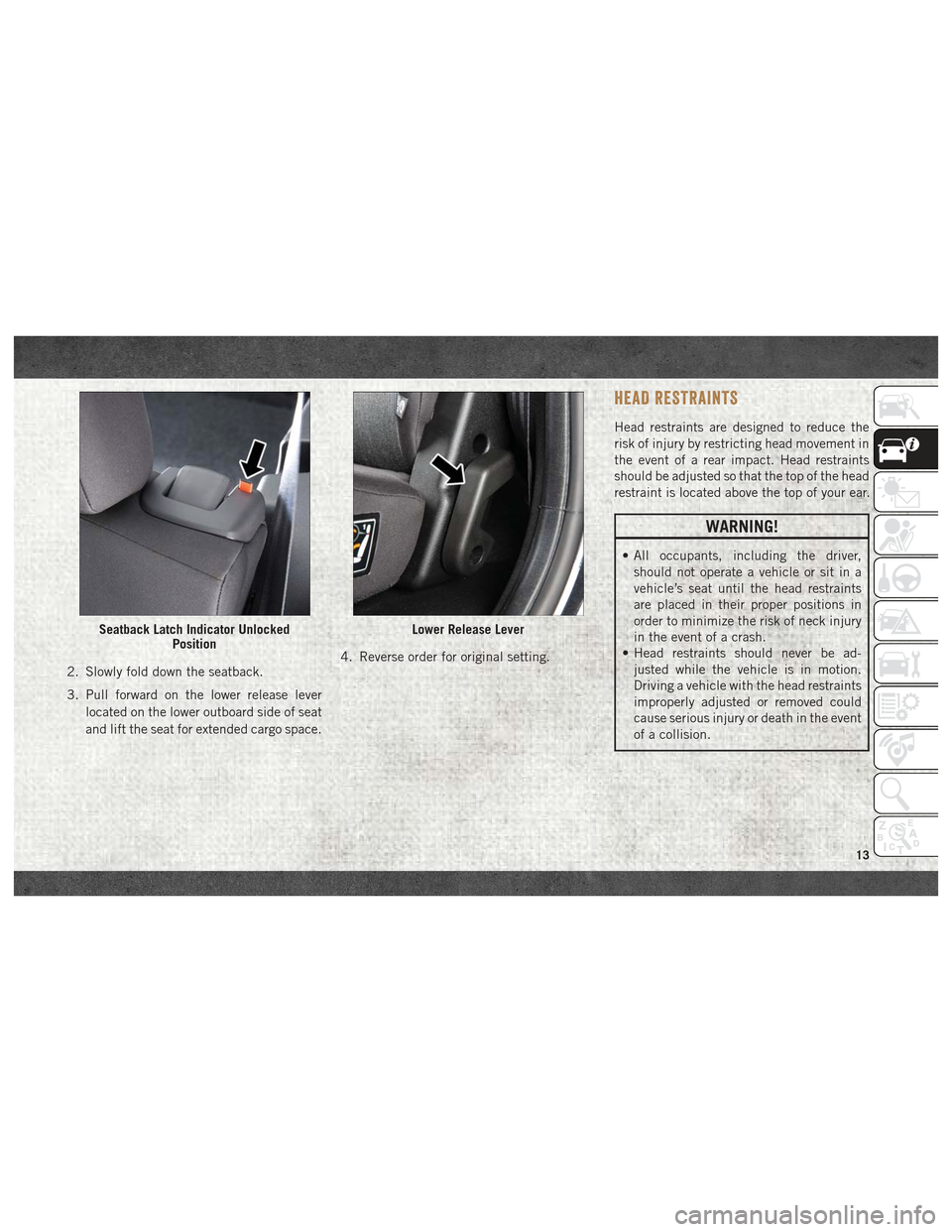
2. Slowly fold down the seatback.
3. Pull forward on the lower release leverlocated on the lower outboard side of seat
and lift the seat for extended cargo space. 4. Reverse order for original setting.
HEAD RESTRAINTS
Head restraints are designed to reduce the
risk of injury by restricting head movement in
the event of a rear impact. Head restraints
should be adjusted so that the top of the head
restraint is located above the top of your ear.
WARNING!
• All occupants, including the driver,
should not operate a vehicle or sit in a
vehicle’s seat until the head restraints
are placed in their proper positions in
order to minimize the risk of neck injury
in the event of a crash.
• Head restraints should never be ad-
justed while the vehicle is in motion.
Driving a vehicle with the head restraints
improperly adjusted or removed could
cause serious injury or death in the event
of a collision.
Seatback Latch Indicator Unlocked PositionLower Release Lever
13
Page 18 of 180
WARNING!
• A loose head restraint thrown forward ina collision or hard stop could cause
serious injury or death to occupants of
the vehicle. Always securely stow re-
moved head restraints in a location out-
side the occupant compartment.
• ALL the head restraints MUST be rein-
stalled in the vehicle to properly protect
the occupants. Follow the re-installation
instructions above prior to operating the
vehicle or occupying a seat.
STEERING WHEEL
Tilt/Telescoping Steering Column
This feature allows you to tilt the steering
column upward or downward. It also allows
you to lengthen or shorten the steering col-
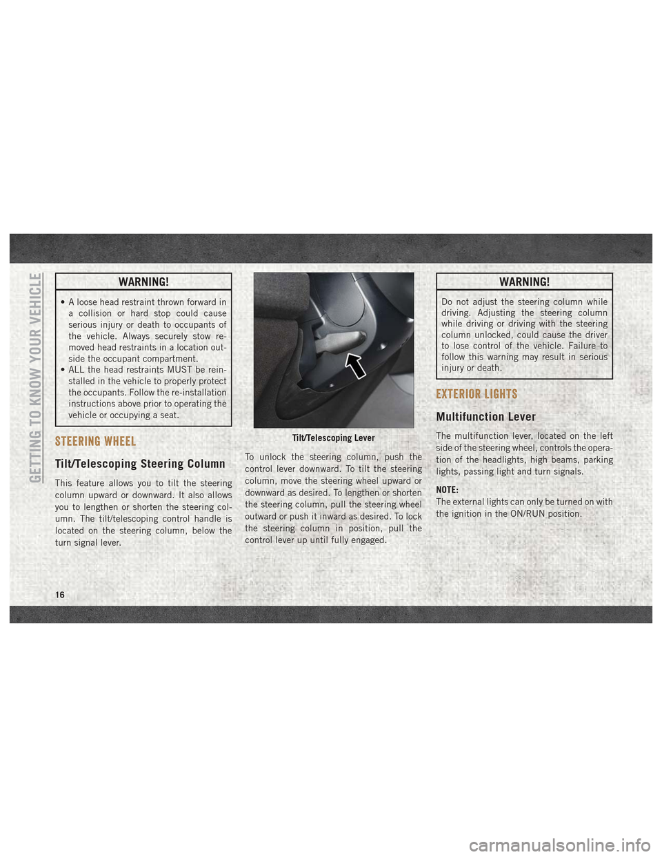
umn. The tilt/telescoping control handle is
located on the steering column, below the
turn signal lever. To unlock the steering column, push the
control lever downward. To tilt the steering
column, move the steering wheel upward or
downward as desired. To lengthen or shorten
the steering column, pull the steering wheel
outward or push it inward as desired. To lock
the steering column in position, pull the
control lever up until fully engaged.
WARNING!
Do not adjust the steering column while
driving. Adjusting the steering column
while driving or driving with the steering
column unlocked, could cause the driver
to lose control of the vehicle. Failure to
follow this warning may result in serious
injury or death.
EXTERIOR LIGHTS
Multifunction Lever
The multifunction lever, located on the left
side of the steering wheel, controls the opera-
tion of the headlights, high beams, parking
lights, passing light and turn signals.
NOTE:
The external lights can only be turned on with
the ignition in the ON/RUN position.Tilt/Telescoping Lever
GETTING TO KNOW YOUR VEHICLE
16
Page 19 of 180
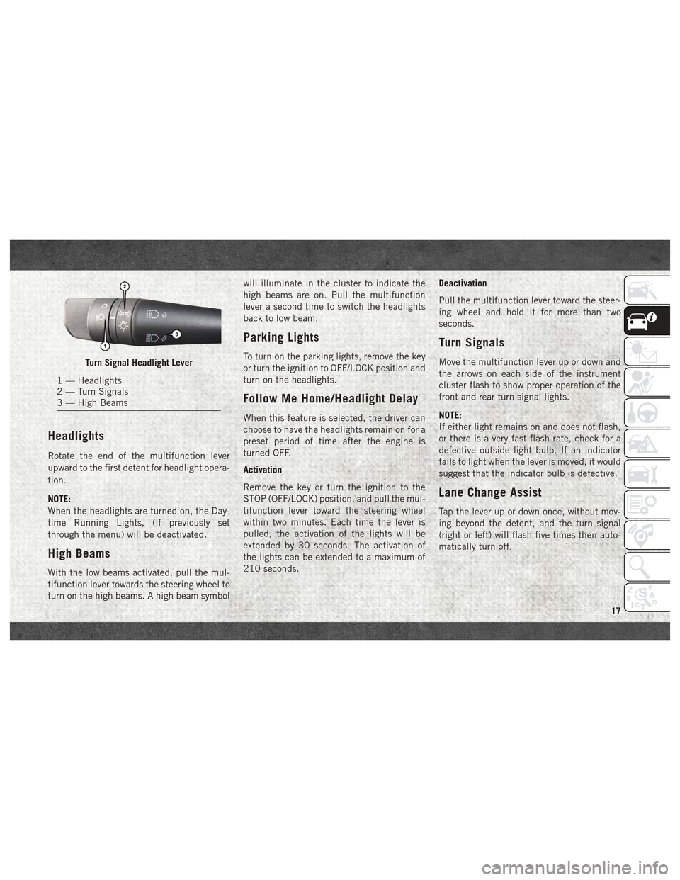
Headlights
Rotate the end of the multifunction lever
upward to the first detent for headlight opera-
tion.
NOTE:
When the headlights are turned on, the Day-
time Running Lights, (if previously set
through the menu) will be deactivated.
High Beams
With the low beams activated, pull the mul-
tifunction lever towards the steering wheel to
turn on the high beams. A high beam symbolwill illuminate in the cluster to indicate the
high beams are on. Pull the multifunction
lever a second time to switch the headlights
back to low beam.
Parking Lights
To turn on the parking lights, remove the key
or turn the ignition to OFF/LOCK position and
turn on the headlights.
Follow Me Home/Headlight Delay
When this feature is selected, the driver can
choose to have the headlights remain on for a
preset period of time after the engine is
turned OFF.
Activation
Remove the key or turn the ignition to the
STOP (OFF/LOCK) position, and pull the mul-
tifunction lever toward the steering wheel
within two minutes. Each time the lever is
pulled, the activation of the lights will be
extended by 30 seconds. The activation of
the lights can be extended to a maximum of
210 seconds.
Deactivation
Pull the multifunction lever toward the steer-
ing wheel and hold it for more than two
seconds.
Turn Signals
Move the multifunction lever up or down and
the arrows on each side of the instrument
cluster flash to show proper operation of the
front and rear turn signal lights.
NOTE:
If either light remains on and does not flash,
or there is a very fast flash rate, check for a
defective outside light bulb. If an indicator
fails to light when the lever is moved, it would
suggest that the indicator bulb is defective.
Lane Change Assist
Tap the lever up or down once, without mov-
ing beyond the detent, and the turn signal
(right or left) will flash five times then auto-
matically turn off.
Turn Signal Headlight Lever
1 — Headlights
2 — Turn Signals
3 — High Beams
17
Page 24 of 180
IconDescription
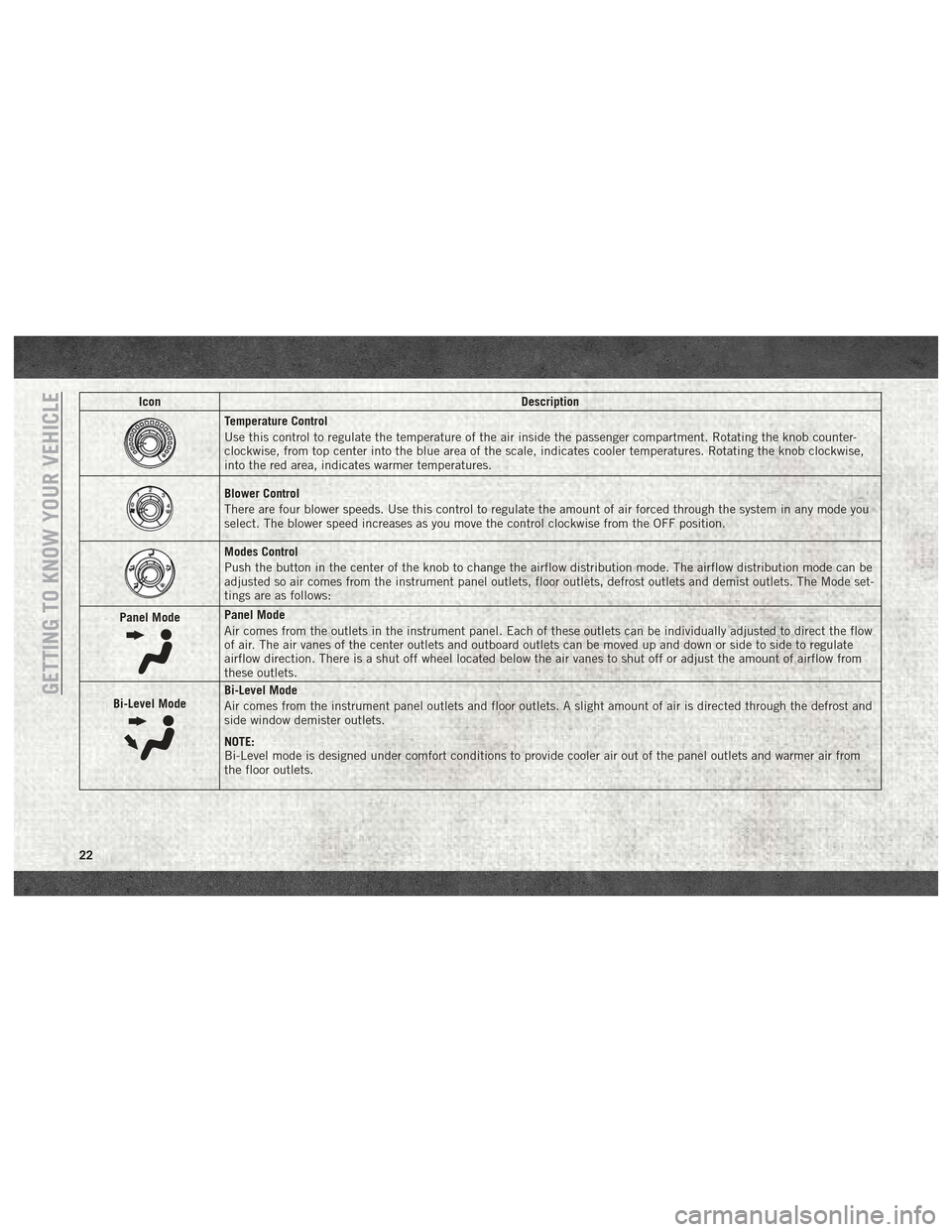
Temperature Control
Use this control to regulate the temperature of the air inside the passenger compartment. Rotating the knob counter-
clockwise, from top center into the blue area of the scale, indicates cooler temperatures. Rotating the knob clockwise,
into the red area, indicates warmer temperatures.
Blower Control
There are four blower speeds. Use this control to regulate the amount of air forced through the system in any mode you
select. The blower speed increases as you move the control clockwise from the OFF position.
Modes Control
Push the button in the center of the knob to change the airflow distribution mode. The airflow distribution mode can be
adjusted so air comes from the instrument panel outlets, floor outlets, defrost outlets and demist outlets. The Mode set-
tings are as follows:
Panel Mode
Panel Mode
Air comes from the outlets in the instrument panel. Each of these outlets can be individually adjusted to direct the flow
of air. The air vanes of the center outlets and outboard outlets can be moved up and down or side to side to regulate
airflow direction. There is a shut off wheel located below the air vanes to shut off or adjust the amount of airflow from
these outlets.
Bi-Level Mode
Bi-Level Mode
Air comes from the instrument panel outlets and floor outlets. A slight amount of air is directed through the defrost and
side window demister outlets.
NOTE:
Bi-Level mode is designed under comfort conditions to provide cooler air out of the panel outlets and warmer air from
the floor outlets.GETTING TO KNOW YOUR VEHICLE
22
Page 27 of 180
Window Fogging
Vehicle windows tend to fog on the inside of
the glass in mild, rainy and/or humid weather.
Windows may frost on the inside of the glass
in very cold weather. To clear the windows,
select Defrost or Mix mode and increase the
front blower speed. Do not use the Recircu-
lation mode without A/C for long periods, as
fogging may occur.
Outside Air Intake
Make sure the air intake, located directly in
front of the windshield, is free of obstructions
such as leaves. Leaves collected in the air
intake may reduce airflow, can cause odor,
and if they enter the plenum they could plug
the water drains. In Winter months make sure
the air intake is clear of ice, slush and snow.
A/C Air Filter
The climate control system filters outside air
containing dust, pollen and some odors.
Strong odors cannot be totally filtered out.
Refer to “Dealer Service” in “Servicing and
Maintenance” in your Owner’s Manual on
www.mopar.com/en-us/care/owners-manual.html
(U.S. Residents) or www.owners.mopar.ca
(Canadian Residents) for filter replacement
instructions.
HOOD
Opening
To open the hood, two latches must be re-
leased.
1. Pull the release lever located below theinstrument panel and in front of the driv-
er's door.
2. Move to the outside of the vehicle, reach into the opening beneath the center of the
hood and push up the safety latch lever to
release it, before raising the hood.
3. Raise the hood and place the hood prop rod in hood slot to secure the hood in the
open position.
CAUTION!
Be sure to disengage the rod and secure it
in close position before closing the hood.
Damage may occur.
Closing
WARNING!
Be sure the hood is fully latched before
driving your vehicle. If the hood is not fully
latched, it could open when the vehicle is
in motion and block your vision. Failure to
follow this warning could result in serious
injury or death.
CAUTION!
To prevent possible damage, do not slam
the hood to close it. Lower hood to approxi-
mately 12 inches (30 cm) and drop the
hood to close. Make sure hood is fully
closed for both latches. Never drive ve-
hicle unless hood is fully closed, with both
latches engaged.
25
Page 33 of 180
•UP Arrow Button
Push and release the uparrow button to
scroll upward through the main menu and
submenus.
• DOWN Arrow Button
Push and release the downarrow button to
scroll downward through the main menu
and submenus.
NOTE:
If equipped with a Uconnect system, some of
the menu items will be present in the radio
head unit. Refer to “Uconnect Settings” in
“Multimedia” in the Owner’s Manual at
www.mopar.com/en-us/care/owners-manual.html
(U.S. Residents) or www.owners.mopar.ca
(Canadian Residents) for further information.
Dimmer:
With headlights on and without entering in
the menu, push the upordown arrow button
to increase or decrease the brightness of the
instrument panel, graphics and command
buttons. Selecting An Option Of The Main Menu With
Submenu:
1. Briefly push and release the
MENUbutton
to display the first submenu option.
2. Push and release the upordown arrow
button (by single pushes) to scroll through
all the submenu options.
3. Briefly push and release the MENUbutton
to select the displayed submenu option
and to open the relevant setup menu.
4. Push and release the upordown arrow
button (by single pushes) to select the
new setting for this submenu option.
5. Briefly push and release the MENUbutton
to store the new setting and go back to the
previously selected submenu option.
6. Push and hold the MENUbutton to return
to the main menu (short hold) or the main
screen (longer hold).
WARNING LIGHTS AND MESSAGES
Red Warning Lights
— Air Bag Warning Light
This light will turn on for four to eight seconds
as a bulb check when the ignition is placed in
the ON/RUN or MAR/ON/RUN position. If the
light is either not on during startup, stays on,
or turns on while driving, have the system
inspected at an authorized dealer as soon as
possible. This light will illuminate with a
single chime when a fault with the Air Bag
Warning Light has been detected, it will stay
on until the fault is cleared. If the light comes
on intermittently or remains on while driving,
have an authorized dealer service the vehicle
immediately.
— Brake Warning Light
This light monitors various brake functions,
including brake fluid level and parking brake
application. If the brake light turns on it may
indicate that the parking brake is applied,
that the brake fluid level is low, or that there
is a problem with the anti-lock brake system
reservoir.
31
Page 34 of 180
If the light remains on when the parking
brake has been disengaged, and the fluid
level is at the full mark on the master cylinder
reservoir, it indicates a possible brake hy-
draulic system malfunction or that a problem
with the Brake Booster has been detected by
the Anti-Lock Brake System (ABS) / Elec-
tronic Stability Control (ESC) system. In this
case, the light will remain on until the condi-
tion has been corrected. If the problem is
related to the brake booster, the ABS pump
will run when applying the brake, and a brake
pedal pulsation may be felt during each stop.
The dual brake system provides a reserve
braking capacity in the event of a failure to a
portion of the hydraulic system. A leak in
either half of the dual brake system is indi-
cated by the Brake Warning Light, which will
turn on when the brake fluid level in the
master cylinder has dropped below a speci-
fied level.
The light will remain on until the cause is
corrected.NOTE:
The light may flash momentarily during sharp
cornering maneuvers, which change fluid
level conditions. The vehicle should have
service performed, and the brake fluid level
checked.
If brake failure is indicated, immediate repair
is necessary.
WARNING!
Driving a vehicle with the red brake light
on is dangerous. Part of the brake system
may have failed. It will take longer to stop
the vehicle. You could have a collision.
Have the vehicle checked immediately.
Vehicles equipped with the Anti-Lock Brake
System (ABS) are also equipped with Elec-
tronic Brake Force Distribution (EBD). In the
event of an EBD failure, the Brake Warning
Light will turn on along with the ABS Light.
Immediate repair to the ABS system is re-
quired.
Operation of the Brake Warning Light can be
checked by turning the ignition switch from
the OFF position to the ON/RUN position. The light should illuminate for approximately
two seconds. The light should then turn off
unless the parking brake is applied or a brake
fault is detected. If the light does not illumi-
nate, have the light inspected by your autho-
rized dealer.
The light also will turn on when the parking
brake is applied with the ignition switch in
the ON/RUN position.
NOTE:
This light shows only that the parking brake is
applied. It does not show the degree of brake
application.
— Battery Charge Warning Light
This light illuminates when the battery is not
charging properly. If it stays on while the
engine is running, there may be a malfunc-
tion with the charging system. Contact your
authorized dealer as soon as possible.
This indicates a possible problem with the
electrical system or a related component.
— Door Open Warning Light
This indicator will illuminate when one or
more door(s) are not fully closed.
GETTING TO KNOW YOUR INSTRUMENT PANEL
32