lock Ram ProMaster City 2018 Owner's Manual
[x] Cancel search | Manufacturer: RAM, Model Year: 2018, Model line: ProMaster City, Model: Ram ProMaster City 2018Pages: 180, PDF Size: 7.52 MB
Page 71 of 180
WARNING!
for attaching other items or equipment
to the vehicle.
Installing Child Restraints Using The Ve-
hicle Seat Belt In Vehicles With Rear Seat-
ing
Child restraint systems are designed to be
secured in vehicle seats by lap belts or the lap
belt portion of a lap/shoulder belt.
WARNING!
• Improper installation or failure to prop-erly secure a child restraint can lead to
failure of the restraint. The child could
be badly injured or killed.
WARNING!
• Follow the child restraint manufacturer’sdirections exactly when installing an in-
fant or child restraint.
The seat belts in the passenger seating posi-
tions are equipped with a Switchable Auto-
matic Locking Retractor (ALR) that is de-
signed to keep the lap portion of the seat belt
tight around the child restraint so that it is
not necessary to use a locking clip. The ALR
retractor can be “switched” into a locked
mode by pulling all of the webbing out of the
retractor and then letting the webbing retract
back into the retractor. If it is locked, the ALR
will make a clicking noise while the webbing
is pulled back into the retractor. Refer to the
“Automatic Locking Mode” description in
“Switchable Automatic Locking Retractors
(ALR)” under “Occupant Restraint Systems”
for additional information on ALR.
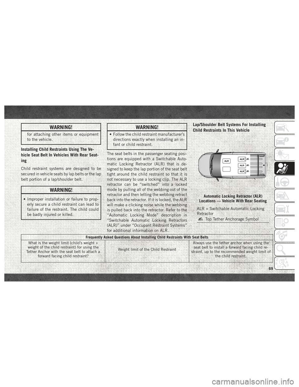
Lap/Shoulder Belt Systems For Installing
Child Restraints In This Vehicle
Frequently Asked Questions About Installing Child Restraints With Seat Belts
What is the weight limit (child’s weight +
weight of the child restraint) for using the
Tether Anchor with the seat belt to attach a forward facing child restraint? Weight limit of the Child RestraintAlways use the tether anchor when using the
seat belt to install a forward facing child re-
straint, up to the recommended weight limit of the child restraint.
Automatic Locking Retractor (ALR)
Locations — Vehicle With Rear Seating
ALR = Switchable Automatic Locking
Retractor
Top Tether Anchorage Symbol
69
Page 72 of 180
Frequently Asked Questions About Installing Child Restraints With Seat Belts
Can the rear-facing child restraint touch the back of the front passenger seat? Ye sContact between the front passenger seat and
the child restraint is allowed, if the child re- straint manufacturer also allows contact.
Can the head restraints be removed? YesSecond Row: The head restraints may be re-
moved from all positions.
Can the buckle stalk be twisted to tighten the seat belt against the belt path of the child re- straint? No
Do not twist the buckle stalk in a seating posi-
tion with an ALR retractor.
Installing A Child Restraint With A Switch-
able Automatic Locking Retractor (ALR):
Child restraint systems are designed to be
secured in vehicle seats by lap belts or the
lap belt portion of a lap/shoulder belt.
WARNING!
• Improper installation or failure to prop-
erly secure a child restraint can lead to
failure of the restraint. The child could
be badly injured or killed.
• Follow the child restraint manufactur-
er’s directions exactly when installing an
infant or child restraint. 1. Place the child seat in the center of the
seating position. For some second row
seats, you may need to recline the seat
and/or raise the head restraint to get a
better fit. If the rear seat can be moved
forward and rearward in the vehicle, you
may wish to move it to its rear-most posi-
tion to make room for the child seat. You
may also move the front seat forward to
allow more room for the child seat.
2. Pull enough of the seat belt webbing from the retractor to pass it through the belt
path of the child restraint. Do not twist the
belt webbing in the belt path.
3. Slide the latch plate into the buckle until you hear a “click.” 4. Pull on the webbing to make the lap
portion tight against the child seat.
5. To lock the seat belt, pull down on the shoulder part of the belt until you have
pulled all the seat belt webbing out of the
retractor. Then, allow the webbing to re-
tract back into the retractor. As the web-
bing retracts, you will hear a clicking
sound. This means the seat belt is now in
the Automatic Locking mode.
6. Try to pull the webbing out of the retractor. If it is locked, you should not be able to
pull out any webbing. If the retractor is
not locked, repeat step 5.
SAFETY
70
Page 74 of 180
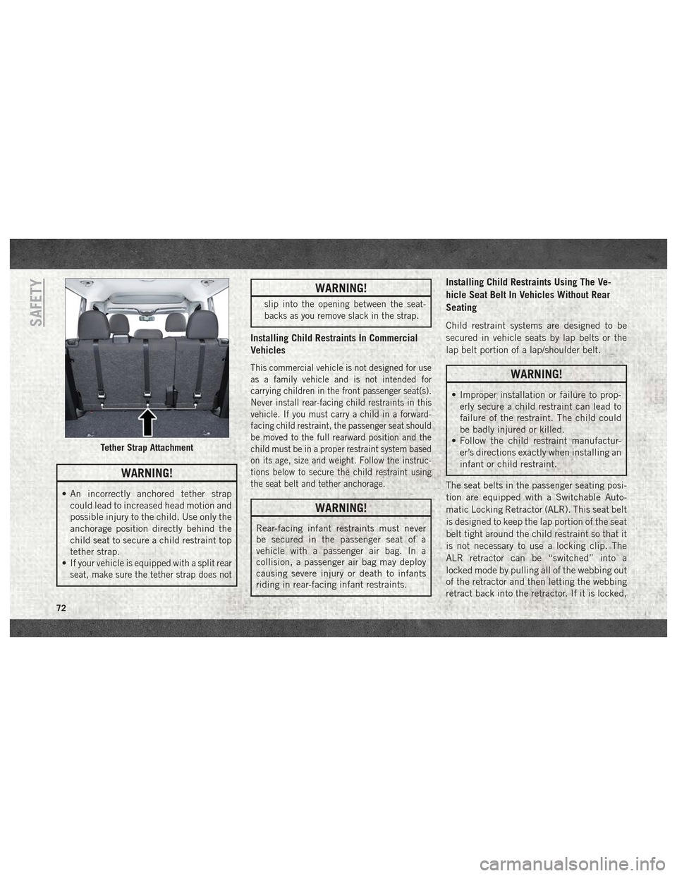
WARNING!
• An incorrectly anchored tether strapcould lead to increased head motion and
possible injury to the child. Use only the
anchorage position directly behind the
child seat to secure a child restraint top
tether strap.
•
If your vehicle is equipped with a split rear
seat, make sure the tether strap does not
WARNING!
slip into the opening between the seat-
backs as you remove slack in the strap.
Installing Child Restraints In Commercial
Vehicles
This commercial vehicle is not designed for use
as a family vehicle and is not intended for
carrying children in the front passenger seat(s).
Never install rear-facing child restraints in this
vehicle. If you must carry a child in a forward-
facing child restraint, the passenger seat should
be moved to the full rearward position and the
child must be in a proper restraint system based
on its age, size and weight. Follow the instruc-
tions below to secure the child restraint using
the seat belt and tether anchorage.
WARNING!
Rear-facing infant restraints must never
be secured in the passenger seat of a
vehicle with a passenger air bag. In a
collision, a passenger air bag may deploy
causing severe injury or death to infants
riding in rear-facing infant restraints.
Installing Child Restraints Using The Ve-
hicle Seat Belt In Vehicles Without Rear
Seating
Child restraint systems are designed to be
secured in vehicle seats by lap belts or the
lap belt portion of a lap/shoulder belt.
WARNING!
• Improper installation or failure to prop-
erly secure a child restraint can lead to
failure of the restraint. The child could
be badly injured or killed.
• Follow the child restraint manufactur-
er’s directions exactly when installing an
infant or child restraint.
The seat belts in the passenger seating posi-
tion are equipped with a Switchable Auto-
matic Locking Retractor (ALR). This seat belt
is designed to keep the lap portion of the seat
belt tight around the child restraint so that it
is not necessary to use a locking clip. The
ALR retractor can be “switched” into a
locked mode by pulling all of the webbing out
of the retractor and then letting the webbing
retract back into the retractor. If it is locked,
Tether Strap Attachment
SAFETY
72
Page 75 of 180
the ALR will make a clicking noise while the
webbing is pulled back into the retractor. For
additional information on ALR, refer to the
“Automatic Locking Mode” description un-
der “Occupant Restraints.”
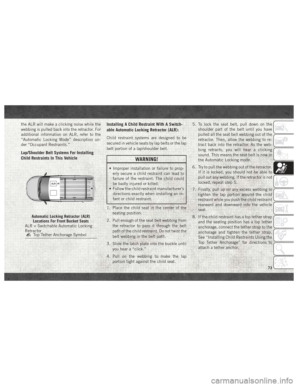
Lap/Shoulder Belt Systems For Installing
Child Restraints In This VehicleInstalling A Child Restraint With A Switch-
able Automatic Locking Retractor (ALR):
Child restraint systems are designed to be
secured in vehicle seats by lap belts or the lap
belt portion of a lap/shoulder belt.
WARNING!
• Improper installation or failure to prop-
erly secure a child restraint can lead to
failure of the restraint. The child could
be badly injured or killed.
• Follow the child restraint manufacturer’s
directions exactly when installing an in-
fant or child restraint.
1. Place the child seat in the center of the seating position.
2. Pull enough of the seat belt webbing from the retractor to pass it through the belt
path of the child restraint. Do not twist the
belt webbing in the belt path.
3. Slide the latch plate into the buckle until you hear a “click.”
4. Pull on the webbing to make the lap portion tight against the child seat. 5. To lock the seat belt, pull down on the
shoulder part of the belt until you have
pulled all the seat belt webbing out of the
retractor. Then, allow the webbing to re-
tract back into the retractor. As the web-
bing retracts, you will hear a clicking
sound. This means the seat belt is now in
the Automatic Locking mode.
6. Try to pull the webbing out of the retractor. If it is locked, you should not be able to
pull out any webbing. If the retractor is not
locked, repeat step 5.
7. Finally, pull up on any excess webbing to tighten the lap portion around the child
restraint while you push the child restraint
rearward and downward into the vehicle
seat.
8. If the child restraint has a top tether strap and the seating position has a top tether
anchorage, connect the tether strap to the
anchorage and tighten the tether strap.
See “Installing Child Restraints Using the
Top Tether Anchorage” for directions to
attach a tether anchor.
Automatic Locking Retractor (ALR)Locations For Front Bucket Seats
ALR = Switchable Automatic Locking
Retractor
Top Tether Anchorage Symbol
73
Page 80 of 180
Periodic Safety Checks You
Should Make Outside The Vehicle
Tires
Examine tires for excessive tread wear and
uneven wear patterns. Check for stones,
nails, glass, or other objects lodged in the
tread or sidewall. Inspect the tread for cuts
and cracks. Inspect sidewalls for cuts,
cracks, and bulges. Check the wheel bolts for
tightness. Check the tires (including spare)
for proper cold inflation pressure.
Lights
Have someone observe the operation of brake
lights and exterior lights while you work the
controls. Check turn signal and high beam
indicator lights on the instrument panel.
Door Latches
Check for proper closing, latching, and lock-
ing.
Fluid Leaks
Check area under the vehicle after overnight
parking for fuel, coolant, oil, or other fluid
leaks. Also, if gasoline fumes are detected or
if fuel, or brake fluid leaks are suspected. The
cause should be located and corrected imme-
diately.
SAFETY
78
Page 86 of 180
CAUTION!
• To avoid vehicle damage, the vehiclemust be driven slowly when using
ParkView to be able to stop in time when
an obstacle is seen. It is recommended
that the driver look frequently over his/
her shoulder when using ParkView.
NOTE:
If snow, ice, mud, or any foreign substance
builds up on the camera lens, clean the lens,
rinse with water, and dry with a soft cloth. Do
not cover the lens.
REFUELING THE VEHICLE
The gas cap is located behind the fuel filler
door on the left side of the vehicle. If the gas
cap is lost or damaged, be sure the replace-
ment cap is for use with this vehicle.
1. Open the fuel filler door.
2. Remove the fuel cap by rotating it counterclockwise. 3. Fully insert the gasoline nozzle into the
filler pipe.
4. Fill the vehicle with fuel.
NOTE:
When the fuel nozzle “clicks” or shuts off,
the fuel tank is full.
5. Remove gasoline nozzle, reinstall fuel cap and close fuel filler door.
WARNING!
• Never have any smoking materials lit inor near the vehicle when the gas cap is
removed or the tank is being filled.
• Never add fuel when the engine is run-
ning. This is in violation of most state
and federal fire regulations and may
cause the MIL to turn on.
• A fire may result if gasoline is pumped
into a portable container that is inside of
a vehicle. You could be burned. Always
place gas containers on the ground while
filling.
CAUTION!
• Damage to the fuel system or emissionscontrol system could result from using
an improper fuel tank filler tube cap. A
poorly fitting cap could let impurities
into the fuel system and may cause the
“Malfunction Indicator Light (MIL)” to
turn on, due to fuel vapors escaping
from the system.
• To avoid fuel spillage and overfilling, do
not “top off” the fuel tank after filling.
NOTE:
• When the fuel nozzle “clicks” or shuts off, the fuel tank is full.
• Tighten the fuel filler cap until you hear a “clicking” sound. This is an indication that
the fuel filler cap is properly tightened.
• If the gas cap is not tightened properly, the MIL may come on. Be sure the gas cap is
tightened every time the vehicle is
refueled.
STARTING AND OPERATING
84
Page 92 of 180
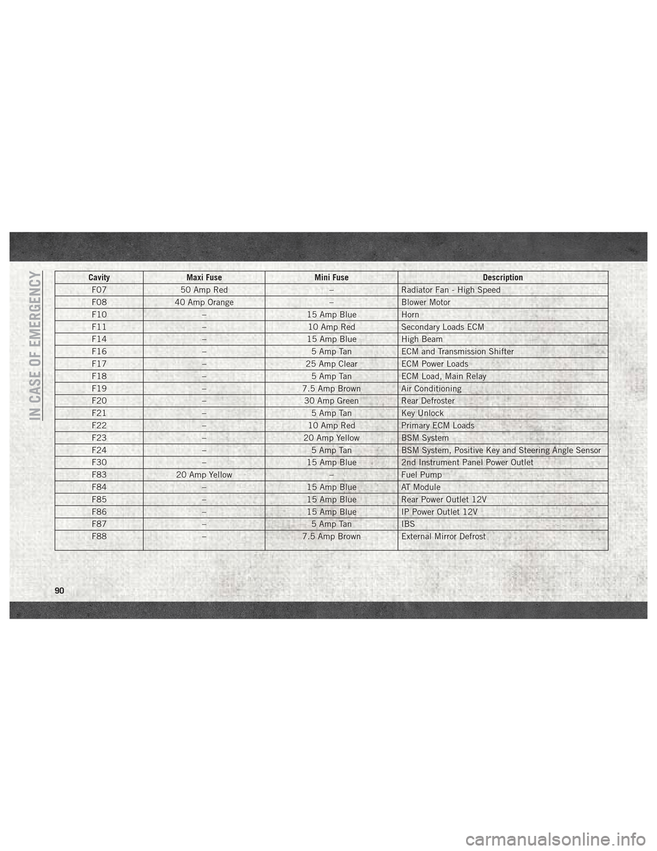
CavityMaxi Fuse Mini Fuse Description
F07 50 Amp Red –Radiator Fan - High Speed
F08 40 Amp Orange –Blower Motor
F10 –15 Amp BlueHorn
F11 –10 Amp RedSecondary Loads ECM
F14 –15 Amp BlueHigh Beam
F16 –5 Amp TanECM and Transmission Shifter
F17 –25 Amp ClearECM Power Loads
F18 –5 Amp TanECM Load, Main Relay
F19 –7.5 Amp Brown Air Conditioning
F20 –30 Amp Green Rear Defroster
F21 –5 Amp TanKey Unlock
F22 –10 Amp RedPrimary ECM Loads
F23 –20 Amp Yellow BSM System
F24 –5 Amp TanBSM System, Positive Key and Steering Angle Sensor
F30 –15 Amp Blue2nd Instrument Panel Power Outlet
F83 20 Amp Yellow –Fuel Pump
F84 –15 Amp BlueAT Module
F85 –15 Amp BlueRear Power Outlet 12V
F86 –15 Amp BlueIP Power Outlet 12V
F87 –5 Amp TanIBS
F88 –7.5 Amp Brown External Mirror Defrost
IN CASE OF EMERGENCY
90
Page 93 of 180
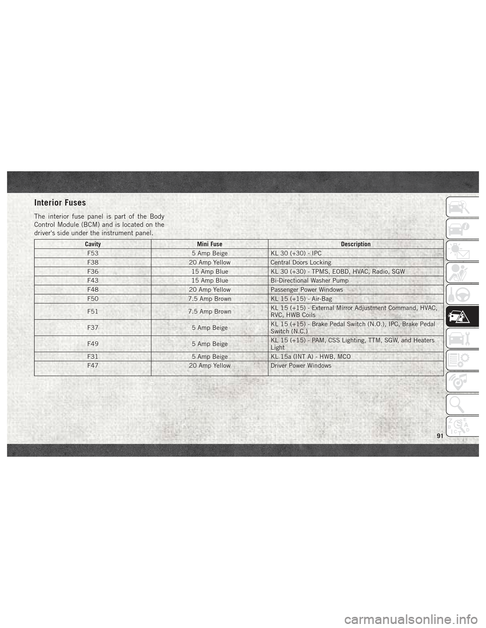
Interior Fuses
The interior fuse panel is part of the Body
Control Module (BCM) and is located on the
driver's side under the instrument panel.
CavityMini Fuse Description
F53 5 Amp BeigeKL 30 (+30) - IPC
F38 20 Amp YellowCentral Doors Locking
F36 15 Amp BlueKL 30 (+30) - TPMS, EOBD, HVAC, Radio, SGW
F43 15 Amp BlueBi-Directional Washer Pump
F48 20 Amp YellowPassenger Power Windows
F50 7.5 Amp BrownKL 15 (+15) - Air-Bag
F51 7.5 Amp BrownKL 15 (+15) - External Mirror Adjustment Command, HVAC,
RVC, HWB Coils
F37 5 Amp BeigeKL 15 (+15) - Brake Pedal Switch (N.O.), IPC, Brake Pedal
Switch (N.C.)
F49 5 Amp BeigeKL 15 (+15) - PAM, CSS Lighting, TTM, SGW, and Heaters
Light
F31 5 Amp BeigeKL 15a (INT A) - HWB, MCO
F47 20 Amp YellowDriver Power Windows
91
Page 96 of 180
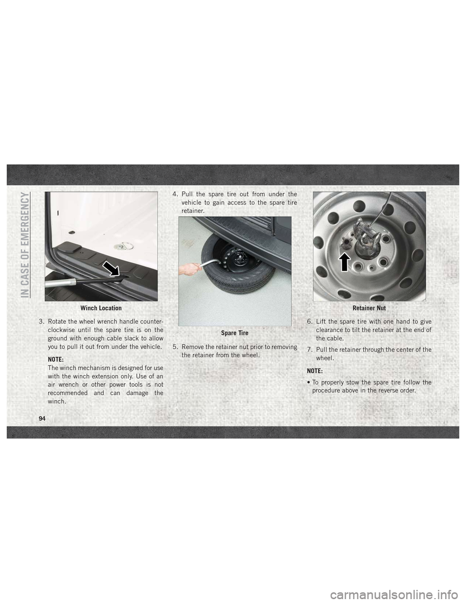
3. Rotate the wheel wrench handle counter-clockwise until the spare tire is on the
ground with enough cable slack to allow
you to pull it out from under the vehicle.
NOTE:
The winch mechanism is designed for use
with the winch extension only. Use of an
air wrench or other power tools is not
recommended and can damage the
winch. 4. Pull the spare tire out from under the
vehicle to gain access to the spare tire
retainer.
5. Remove the retainer nut prior to removing the retainer from the wheel. 6. Lift the spare tire with one hand to give
clearance to tilt the retainer at the end of
the cable.
7. Pull the retainer through the center of the wheel.
NOTE:
• To properly stow the spare tire follow the procedure above in the reverse order.
Winch Location
Spare Tire
Retainer Nut
IN CASE OF EMERGENCY
94
Page 97 of 180
• When winching the tire back into place, thewinch will make three audible noises once
secure. Reach underneath and shake tire
by hand to confirm that it is secure. The tire
should not move. If tire is still loose and/or
three audible noises are not heard, place
and secure damaged wheel into the vehicle
and seek dealer assistance for the winch
mechanism.
Preparations For Jacking
1. Park the vehicle on a firm level surface as
far from the edge of the roadway as pos-
sible. Avoid icy or slippery areas.
WARNING!
Do not attempt to change a tire on the side
of the vehicle close to moving traffic, pull
far enough off the road to avoid being hit
when operating the jack or changing the
wheel.
2. Turn on the Hazard Warning flasher.
3. Apply the parking brake. 4. Place the gear selector into PARK.
5. Turn the ignition off to the LOCK position.
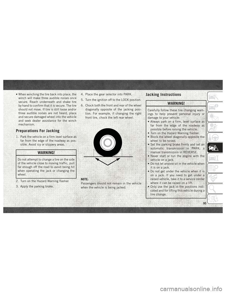
6. Chock both the front and rear of the wheel
diagonally opposite of the jacking posi-
tion. For example, if changing the right
front tire, chock the left rear wheel.
NOTE:
Passengers should not remain in the vehicle
when the vehicle is being jacked.
Jacking Instructions
WARNING!
Carefully follow these tire changing warn-
ings to help prevent personal injury or
damage to your vehicle:
• Always park on a firm, level surface as far from the edge of the roadway as
possible before raising the vehicle.
• Turn on the Hazard Warning flasher.
• Block the wheel diagonally opposite the
wheel to be raised.
• Set the parking brake firmly and set an
automatic transmission in PARK; a
manual transmission in REVERSE.
• Never start or run the engine with the
vehicle on a jack.
• Do not let anyone sit in the vehicle when
it is on a jack.
• Do not get under the vehicle when it is
on a jack. If you need to get under a
raised vehicle, take it to a service center
where it can be raised on a lift.
• Only use the jack in the positions indi-
cated and for lifting this vehicle during a
tire change.
95