technical specifications Ram ProMaster City 2019 Owner's Manual
[x] Cancel search | Manufacturer: RAM, Model Year: 2019, Model line: ProMaster City, Model: Ram ProMaster City 2019Pages: 348, PDF Size: 3.75 MB
Page 3 of 348
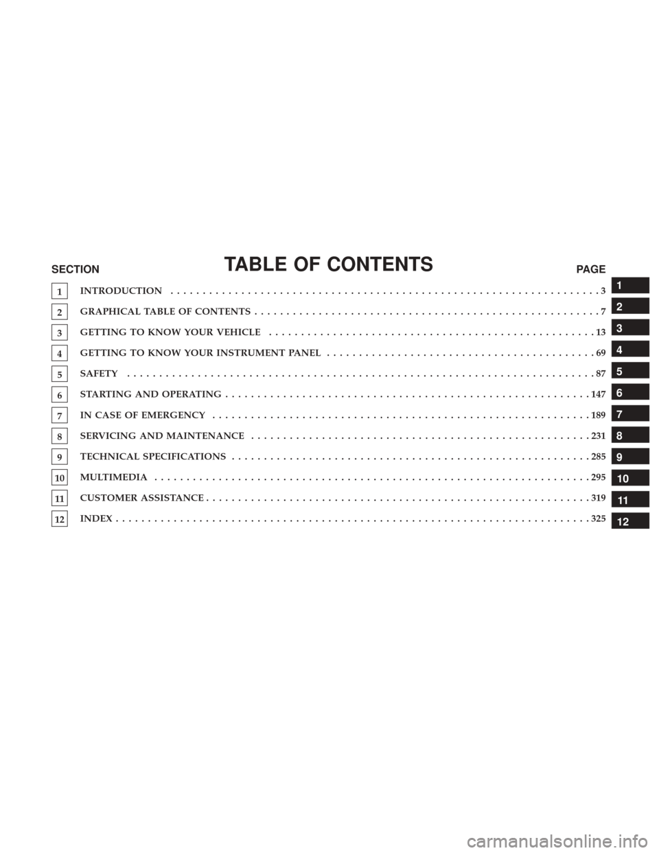
TABLE OF CONTENTSSECTIONPAGE
1INTRODUCTION
...................................................................3
2GRAPHICAL TABLE OF CONTENTS
......................................................7
3GETTING TO KNOW YOUR VEHICLE
...................................................13
4GETTING TO KNOW YOUR INSTRUMENT PANEL .
.........................................69
5SAFETY
........................................................................\
.87
6STARTINGANDOPERATING.........................................................147
7INCASEOFEMERGENCY ...........................................................189
8SERVICING AND MAINTENANCE
.....................................................231
9TECHNICAL SPECIFICATIONS
........................................................285
10MULTIMEDIA ....................................................................295
11CUSTOMER ASSISTANCE
............................................................319
12INDEX........................................................................\
..325
1
2
3
4
5
6
7
8
9
10 11
12
Page 7 of 348
HOW TO USE THIS MANUAL
Essential Information
Consult the Table of Contents to determine which section
contains the information you desire.
Since the specification of your vehicle depends on the items
of equipment ordered, certain descriptions and illustra-
tions may differ from your vehicle’s equipment.
The detailed index at the back of this Owner’s Manual
contains a complete listing of all subjects.
Symbols
Some vehicle components have colored labels whose sym-
bols indicate precautions to be observed when using this
component. Refer to “Warning Lights and Messages” in
“Getting To Know Your Instrument Panel” for further
information on the symbols used in your vehicle.
WARNINGS AND CAUTIONS
This Owner ’s Manual containsWARNINGSagainst oper-
ating procedures that could result in a collision, bodily
injury and/or death. It also contains CAUTIONSagainst
procedures that could result in damage to your vehicle. If you do not read this entire Owner ’s Manual, you may miss
important information. Observe all Warnings and Cau-
tions.
VAN CONVERSIONS/CAMPERS
The New Vehicle Limited Warranty does not apply to body
modifications or special equipment installed by van
conversion/camper manufacturers/body builders. U.S.
residents refer to the Warranty Information book, Section
2.1.C. Canadian residents refer to the “What Is Not Cov-
ered” section of the Warranty Information book. Such
equipment includes video monitors, VCRs, heaters, stoves,
refrigerators, etc. For warranty coverage and service on
these items, contact the applicable manufacturer.
Operating instructions for the special equipment installed
by the conversion/camper manufacturer should also be
supplied with your vehicle. If these instructions are miss-
ing, please contact your authorized dealer for assistance in
obtaining replacement documents from the applicable
manufacturer.
For information on the Body Builder ’s Guide refer to
www.rambodybuilder.com. This website contains dimen-
sional and technical specifications for your vehicle. It is
1
INTRODUCTION 5
Page 54 of 348
Climate Control Functions
A/C (Air Conditioning)
The Air Conditioning (A/C) button allows the operator to
manually activate or deactivate the air conditioning sys-
tem. When the air conditioning system is turned on, cool
dehumidified air will flow through the outlets into the
cabin. For improved fuel economy, press the A/C button to
turn off the air conditioning and manually adjust the
blower and airflow mode settings. Also, make sure to select
only Panel, Bi-Level or Floor modes.
NOTE:
•For Manual Climate Controls, if the system is in Mix,
Floor or Defrost Mode, the A/C can be turned off, but
the A/C system shall remain active to prevent fogging of
the windows.
• If fog or mist appears on the windshield or side glass,
select Defrost mode, and increase blower speed if
needed.
• If your air conditioning performance seems lower than
expected, check the front of the A/C condenser (located
in front of the radiator), for an accumulation of dirt or
insects. Clean with a gentle water spray from the front of
the radiator and through the condenser.
Recirculation
In cold weather, use of Recirculation mode may lead to
excessive window fogging. The Recirculation feature may
be unavailable (button on the touchscreen greyed out) if
conditions exist that could create fogging on the inside of
the windshield.
On systems with Manual Climate Controls, if equipped,
the Recirculation mode is not allowed in Defrost mode to
improve window clearing operation. Recirculation is dis-
abled automatically if this mode is selected. Attempting to
use Recirculation while in this mode causes the LED in the
control button to blink and then turns off.
Operating Tips
NOTE: Refer to the chart at the end of this section for
suggested control settings for various weather conditions.
Summer Operation
The engine cooling system must be protected with a
high-quality antifreeze coolant to provide proper corrosion
protection and to protect against engine overheating. OAT
coolant (conforming to MS.90032) is recommended. Refer
to “Fluids and Lubricants” in “Technical Specifications” for
proper coolant selection.
52 GETTING TO KNOW YOUR VEHICLE
Page 55 of 348
Winter Operation
To ensure the best possible heater and defroster perfor-
mance, make sure the engine cooling system is functioning
properly and the proper amount, type, and concentration
of coolant is used. Refer to “Fluids and Lubricants” in
“Technical Specifications” for proper coolant selection. Use
of the air recirculation mode during Winter months is not
recommended because it may cause window fogging.
Vacation/Storage
Any time you store your vehicle or keep it out of service
(i.e., vacation) for two weeks or more, run the air condi-
tioning system at idle for about five minutes in fresh air
with the blower setting on high. This will ensure adequate
system lubrication to minimize the possibility of compres-
sor damage when the system is started again.
Window Fogging
Vehicle windows tend to fog on the inside of the glass in
mild, rainy and/or humid weather. Windows may frost on
the inside of the glass in very cold weather. To clear the
windows, select Defrost or Mix mode and increase the
front blower speed. Do not use the Recirculation mode
without A/C for long periods, as fogging may occur.
CAUTION!
Failure to follow these cautions can cause damage to
the heating elements:
•Use care when washing the inside of the rear win-
dow. Do not use abrasive window cleaners on the
interior surface of the window. Use a soft cloth and a
mild washing solution, wiping parallel to the heat-
ing elements. Labels can be peeled off after soaking
with warm water.
•
Do not use scrapers, sharp instruments, or abrasive
window cleaners on the interior surface of the window.
• Keep all objects a safe distance from the window.
Outside Air Intake
Make sure the air intake, located directly in front of the
windshield, is free of obstructions such as leaves. Leaves
collected in the air intake may reduce airflow, can cause
odor, and if they enter the plenum they could plug the
water drains. In Winter months make sure the air intake is
clear of ice, slush and snow.
Cabin Air Filter
The climate control system filters out dust and pollen from
the air. Contact an authorized dealer to service your cabin
air filter, and to have it replaced when needed.
3
GETTING TO KNOW YOUR VEHICLE 53
Page 154 of 348
•The engine block heater must be plugged in at least one
hour to have an adequate warming effect on the engine.
WARNING!
Remember to disconnect the engine block heater cord
before driving. Damage to the 110-115 Volt electrical
cord could cause electrocution.
ENGINE BREAK-IN RECOMMENDATIONS
A long break-in period is not required for the engine and
drivetrain (transmission and axle) in your vehicle.
Drive moderately during the first 300 miles (500 km). After
the initial 60 miles (100 km), speeds up to 50 or 55 mph (80
or 90 km/h) are desirable.
While cruising, brief full-throttle acceleration within the
limits of local traffic laws contributes to a good break-in.
Wide-open throttle acceleration in low gear can be detri-
mental and should be avoided.
The engine oil installed in the engine at the factory is a
high-quality energy conserving type lubricant. Oil changes
should be consistent with anticipated climate conditions under which vehicle operations will occur. For the recom-
mended viscosity and quality grades, refer to “Fluids And
Lubricants” in “Technical Specifications”.
CAUTION!
Never use Non-Detergent Oil or Straight Mineral Oil
in the engine or damage may result.
NOTE: A new engine may consume some oil during its
first few thousand miles (kilometers) of operation. This
should be considered a normal part of the break-in and not
interpreted as a problem. Please check your oil level with
the engine oil indicator often during the break in period.
Add oil as required.
PARKING BRAKE
Before leaving the vehicle, make sure that the parking
brake is fully applied. Also, be certain to leave an auto-
matic transmission in PARK, or manual transmission in
REVERSE or first gear.
The parking brake lever is located in the center console. To
apply the parking brake, pull the lever up as firmly as
152 STARTING AND OPERATING
Page 165 of 348
NOTE:
•Increased noise levels at the end of the steering wheel
travel are considered normal and do not indicate that
there is a problem with the power steering system.
• Upon initial start-up in cold weather, the power steering
pump may make noise for a short amount of time. This
is due to the cold, thick fluid in the steering system. This
noise should be considered normal, and it does not in
any way damage the steering system.
CAUTION!
Prolonged operation of the steering system at the end of
the steering wheel travel will increase the steering fluid
temperature and it should be avoided when possible.
Damage to the power steering pump may occur.
Power Steering Fluid Check
Checking the power steering fluid level at a defined service
interval is not required. The fluid should only be checked
if a leak is suspected, abnormal noises are apparent,
and/or the system is not functioning as anticipated. Coor-
dinate inspection efforts through your authorized dealer.
WARNING!
Fluid level should be checked on a level surface and
with the engine off to prevent injury from moving
parts and to ensure accurate fluid level reading. Do not
overfill. Use only manufacturer’s recommended power
steering fluid.
CAUTION!
Do not use chemical flushes in your power steering
system as the chemicals can damage your power steer-
ing components. Such damage is not covered by the
New Vehicle Limited Warranty.
If necessary, add fluid to restore to the proper indicated
level. With a clean cloth, wipe any spilled fluid from all
surfaces. Refer to “Fluids And Lubricants” in “Technical
Specifications” for further information.
6
STARTING AND OPERATING 163
Page 215 of 348
5. Remove the wheel lug bolts. For vehicles with wheelcovers, remove the cover from the wheel by hand. Do
not pry the wheel cover off. Then pull the wheel off the
hub.
6. Install the spare tire. Lightly tighten the wheel lug bolts using the bolt install wrench.
WARNING!
To avoid the risk of forcing the vehicle off the jack, do
not fully tighten the wheel bolts until the vehicle has
been lowered. Failure to follow this warning may
result in serious injury.
CAUTION!
Be sure to mount the spare tire with the valve stem
facing outward. The vehicle could be damaged if the
spare tire is mounted incorrectly.
7. Lower the vehicle by turning the jack screw to the left.
8. Refer to “Torque Specifications” in “Technical Specifica- tions” for proper wheel lug bolt torque.
9. Lower the jack to its fully-closed position.
Mounting Spare Tire
7
IN CASE OF EMERGENCY 213
Page 218 of 348
Vehicles Equipped With Wheel Covers
1. Mount the road tire on the axle.
2. To ease the installation process for steel wheels withwheel covers, install two wheel bolts on the wheel.
Install the wheel bolts with the threaded end of the bolt
toward the wheel. Lightly tighten the wheel bolts. 3. Align the valve notch in the wheel cover with the valve
stem on the wheel. Install the cover by hand, snapping
the cover over the two wheel bolts. Do not use a
hammer or excessive force to install the cover.
4. Install the remaining wheel bolts with the threaded end of the wheel bolt toward the wheel. Lightly tighten the
wheel bolts.
WARNING!
To avoid the risk of forcing the vehicle off the jack, do
not fully tighten the wheel bolts until the vehicle has
been lowered. Failure to follow this warning may
result in serious injury.
5. Lower the vehicle to the ground by turning the jack handle counterclockwise.
6. Finish tightening the wheel bolts. Push down on the wrench while holding at the end of the handle for
increased leverage. Tighten the wheel bolts in a star
pattern until each wheel bolt has been tightened twice.
Refer to “Torque Specifications” in “Technical Specifica-
tions” for correct wheel bolt torque.
Tire And Wheel Cover Or Center Cap
1 — Valve Stem 4 — Wheel Cover
2 — Valve Notch 5 — Road Wheel
3 — Wheel Bolt 216 IN CASE OF EMERGENCY
Page 253 of 348
WARNING!
Riding the brakes can lead to brake failure and possi-
bly a collision. Driving with your foot resting or riding
on the brake pedal can result in abnormally high brake
temperatures, excessive lining wear, and possible
brake damage. You would not have your full braking
capacity in an emergency.
Brake Master Cylinder
The fluid in the master cylinder should be checked when
performing under hood services or immediately if the
“Brake Warning Light” is illuminated.
Be sure to clean the top of the master cylinder area before
removing the cap. If necessary, add fluid to bring the fluid
level up to the requirements described on the brake fluid
reservoir. With disc brakes, fluid level can be expected to
fall as the brake pads wear. Brake fluid level should be
checked when pads are replaced. However, low fluid level
may be caused by a leak and a checkup may be needed.
Use only manufacturer’s recommended brake fluid. Refer
to “Fluids And Lubricants” in “Technical Specifications”
for further information.
WARNING!
•Use only manufacturer’s recommended brake fluid.
Refer to “Fluids And Lubricants” in “Technical
Specifications” for further information. Using the
wrong type of brake fluid can severely damage your
brake system and/or impair its performance. The
proper type of brake fluid for your vehicle is also
identified on the original factory installed hydraulic
master cylinder reservoir.
• To avoid contamination from foreign matter or mois-
ture, use only new brake fluid or fluid that has been
in a tightly closed container. Keep the master cylin-
der reservoir cap secured at all times. Brake fluid in
a open container absorbs moisture from the air
resulting in a lower boiling point. This may cause it
to boil unexpectedly during hard or prolonged brak-
ing, resulting in sudden brake failure. This could
result in a collision.
• Overfilling the brake fluid reservoir can result in
spilling brake fluid on hot engine parts, causing the
brake fluid to catch fire. Brake fluid can also damage
painted and vinyl surfaces, care should be taken to
avoid its contact with these surfaces.
(Continued)
8
SERVICING AND MAINTENANCE 251
Page 254 of 348
WARNING!(Continued)
•Do not allow petroleum based fluid to contaminate
the brake fluid. Brake seal components could be
damaged, causing partial or complete brake failure.
This could result in a collision.
Power Steering Fluid
Check the fluid level with the vehicle on flat ground and
engine cold. Fluid should be between MIN and MAX
references on the reservoir body.
The level may go over the MAX line when oil is hot.
If topping off is required, make sure the oil you use is
approved. Refer to “Fluids And Lubricants” in “Technical
Specifications” for further information.
WARNING!
Because it is flammable, do not allow the power
steering fluid to come into contact with hot engine
parts
NOTE: Power steering fluid consumption is very low. If
you need to top off your fluid often and multiple times
have your system inspected by your authorized dealer.
Automatic Transmission
Selection Of Lubricant
It is important to use the proper transmission fluid to
ensure optimum transmission performance and life. Use
only the manufacturer’s specified transmission fluid. Refer
to “Fluids And Lubricants” in “Technical Specifications”
for fluid specifications. It is important to maintain the
transmission fluid at the correct level using the recom-
mended fluid.
NOTE: No chemical flushes should be used in any trans-
mission; only the approved lubricant should be used.
CAUTION!
Using a transmission fluid other than the manufactur-
er ’s recommended fluid may cause deterioration in
transmission shift quality and/or torque converter
shudder. Refer to “Fluids And Lubricants” in “Techni-
cal Specifications” for fluid specifications.
252 SERVICING AND MAINTENANCE