turn signal Ram ProMaster City 2020 User Guide
[x] Cancel search | Manufacturer: RAM, Model Year: 2020, Model line: ProMaster City, Model: Ram ProMaster City 2020Pages: 350, PDF Size: 13.27 MB
Page 48 of 350

GETTING TO KNOW YOUR VEHICLE 45
Deactivation
Pull the multifunction lever toward the steering wheel and
hold it for more than two seconds.
Fog Lights — If Equipped
The fog light switch is located on the center stack of the
instrument panel, just below the climate controls.Push the switch once to turn the fog lights on.
Push the switch a second time to turn the fog
lights off.
NOTE:
If the vehicle’s ignition is turned off, the fog lights will also
turn off.
Turn Signals
Move the multifunction lever up or down and the arrows on
each side of the instrument cluster flash to show proper oper -
ation of the front and rear turn signal lights.
NOTE:
If either light remains on and does not flash, or there is a very
fast flash rate, check for a defective outside light bulb. If an
indicator fails to light when the lever is moved, it would
suggest that the indicator bulb is defective.
Lane Change Assist
Tap the lever up or down once, without moving beyond the
detent, and the turn signal (right or left) will flash five times
then automatically turn off.
2
2020_RAM_PROMASTER_CITY_OM_USA=GUID-7B6A7FCA-79B0-423F-95C5-ED2A949C3D13=1=en=.book Page 45
Page 84 of 350

GETTING TO KNOW YOUR INSTRUMENT PANEL 81
Push the MENU button briefly to return to the menu screen
or hold the MENU button down to return to the standard
screen without storing.
To cancel the setting:
1. Briefly push the MENU button, “ON” will flash in the
display.
2. Push the down arrow button, “OFF” will flash in the
display.
3. Push the MENU button briefly to return to the menu
screen or hold the MENU button down to return to the
standard screen without storing.
Trip B Data
This function can be used to activate (On) or deactivate (Off)
the Trip B display (Partial Trip).
Refer to “Trip Computer” in this section for further informa -
tion. To switch the function On/Off:
1. Push the
MENU button briefly. The display will flash On
or Off according to the previous setting.
2. Push and release the up or down arrow button to select.
Push the MENU button briefly to return to the menu screen
or hold the MENU button down to return to the standard
screen without storing.
Buzzer Volume
With this function, the volume of the acoustic signal which
accompanies the display of failure/warning can be adjusted
according to seven levels.
To set the desired volume:
1. Push the MENU button, the previously set volume level
will flash on the display.
2. Push and release the up or down arrow button to adjust.
3. Push the MENU button to return to the menu screen or
hold the MENU button down to return to the standard
screen without storing.
3
2020_RAM_PROMASTER_CITY_OM_USA=GUID-7B6A7FCA-79B0-423F-95C5-ED2A949C3D13=1=en=.book Page 81
Page 85 of 350

82 GETTING TO KNOW YOUR INSTRUMENT PANEL
Seat Belt Buzzer
Only shows in the instrument cluster display if the seat belt
reminder was previously deactivated by an authorized dealer.
NOTE:
This is a one-time occurrence to enable the acoustic signal.
Exit Menu
This is the last function that closes the cycle of settings listed
in the menu screen.
1. Pushing the MENU button briefly will return the display
to the standard screen without storing.
2. Push the down arrow button to return to the first menu
item on the display.
TRIP COMPUTER
The Trip Computer is located in the instrument cluster. It
features a driver-interactive display (displays information
such as trip information, range, fuel consumption, average
speed, and travel time).
NOTE:
The Uconnect System also has a Trip Computer display and
menus to customize the information displayed in the cluster. For further information, refer to “Uconnect Settings” in
“Multimedia”.
Trip Button
The
TRIP button, located on the right steering column stalk,
can be used to display and to reset the previously described
values.
• A short button push displays the different values.
• A long button push resets the system and then starts a new trip.
New Trip
To reset:
• Push and hold the TRIP button to reset the system manually.
• When the “Trip distance” reaches 99999.9 miles or kilome -
ters or when the “Travel time” reaches 999.59 (999 hours
and 59 minutes), the system is reset automatically.
• Disconnecting/Reconnecting the battery resets the system.
NOTE:
If the reset operation occurs in the presence of the screens
concerning Trip A or Trip B, only the information associated
with Trip A or Trip B functions will be reset.
2020_RAM_PROMASTER_CITY_OM_USA=GUID-7B6A7FCA-79B0-423F-95C5-ED2A949C3D13=1=en=.book Page 82
Page 87 of 350

84 GETTING TO KNOW YOUR INSTRUMENT PANEL
NOTE:
The range depends on several factors: driving style, type of
route (freeway, residential, mountain roads, etc.), conditions
of use of the vehicle (load, tire pressure, etc.). Trip planning
must take into account the above notes.
Travel Distance
This value shows the distance covered since the last reset.
Average Fuel Consumption
This value shows the approximate average consumption
since the last reset.
Current Fuel Consumption
This indicates the fuel consumption. The value is constantly
updated. The message “----” will appear on the display if the
vehicle is parked with the engine running.
Average Speed
This value shows the vehicle's average speed as a function of
the overall time elapsed since the last reset.
Travel Time
This value shows the time elapsed since the last reset.WARNING LIGHTS AND MESSAGES
The warning/indicator lights will illuminate in the instrument
panel together with a dedicated message and/or acoustic signal
when applicable. These indications are indicative and precau-
tionary and as such must not be considered as exhaustive and/
or alternative to the information contained in the Owner’s
Manual, which you are advised to read carefully in all cases.
Always refer to the information in this chapter in the event of a
failure indication. All active telltales will display first if appli -
cable. The system check menu may appear different based upon
equipment options and current vehicle status. Some telltales are
optional and may not appear.
Red Warning Lights
Air Bag Warning Light
This light will turn on for four to eight seconds as a bulb
check when the ignition is placed in the ON/RUN or
MAR/ON/RUN position. If the light is either not on
during startup, stays on, or turns on while driving, have the
system inspected at an authorized dealer as soon as possible.
This light will illuminate with a single chime when a fault with
the Air Bag Warning Light has been detected, it will stay on until
the fault is cleared. If the light comes on intermittently or
remains on while driving, have an authorized dealer service the
vehicle immediately.
2020_RAM_PROMASTER_CITY_OM_USA=GUID-7B6A7FCA-79B0-423F-95C5-ED2A949C3D13=1=en=.book Page 84
Page 95 of 350

92 GETTING TO KNOW YOUR INSTRUMENT PANEL
Electronic Stability Control (ESC) Warning Light — If
Equipped
The Electronic Stability Control (ESC) Indicator Light in
the instrument cluster will come on when the ignition is
placed in the ON/RUN or MAR/ON/RUN position, and
when ESC is activated. It should go out with the engine running. If
the “ESC Indicator Light” comes on continuously with the engine
running, a malfunction has been detected in the ESC system. If this
light remains on after several ignition cycles, and the vehicle has
been driven several miles (kilometers) at speeds greater than
30 mph (48 km/h), see your authorized dealer as soon as possible
to have the problem diagnosed and corrected.
• The “ESC OFF Indicator Light” and the “ESC Indicator Light” come on momentarily each time the ignition is
placed in the ON/RUN or MAR/ON/RUN position.
• Each time the ignition is turned to ON/RUN or MAR/ON/ RUN, the ESC system will be on, even if it was turned off
previously.
• The ESC system will make buzzing or clicking sounds when it is active. This is normal; the sounds will stop when
ESC becomes inactive.
• This light will come on when the vehicle is in an ESC event. Electronic Stability Control (ESC) OFF Warning Light —
If Equipped
This warning light indicates the Electronic Stability
Control (ESC) is off.
Each time the ignition is turned to ON/RUN or ACC/ON/RUN,
the ESC system will be on, even if it was turned off previously.
Green Indicator Lights
Turn Signal Indicator Lights When the left or right turn signal is activated, the
turn signal indicator will flash independently and
the corresponding exterior turn signal lamps will
flash. Turn signals can be activated when the multifunction
lever is moved down (left) or up (right).
NOTE:
• A continuous chime will sound if the vehicle is driven more than 1 mile (1.6 km) with either turn signal on.
• Check for an inoperative outside light bulb if either indicator flashes at a rapid rate.
2020_RAM_PROMASTER_CITY_OM_USA=GUID-7B6A7FCA-79B0-423F-95C5-ED2A949C3D13=1=en=.book Page 92
Page 108 of 350

SAFETY 105
Base SystemThis is the TPMS warning indicator located in the
instrument cluster.
The TPMS uses wireless technology with wheel rim
mounted electronic sensors to monitor tire pressure levels.
Sensors, mounted to each wheel as part of the valve stem,
transmit tire pressure readings to the Receiver Module.
NOTE:
It is particularly important for you to check the tire pressure
in all of the tires on your vehicle regularly and to maintain
the proper pressure.
The TPMS consists of the following components:
• Receiver Module
• Four Tire Pressure Monitoring sensors
• Tire Pressure Monitoring System Warning Light
Tire Pressure Monitoring Low Pressure Warnings
The Tire Pressure Monitoring System Warning Light will
illuminate in the instrument cluster, an audible chime will be
activated, and the “Check tire pressure” text message will
display when one or more of the four active road tire pres -
sures are low. Should this occur, you should stop as soon as possible, check the inflation pressure of each tire on your
vehicle, and inflate each tire to the vehicle’s recommended
cold placard pressure value. The system will automatically
update and the Tire Pressure Monitoring Light will extin
-
guish once the updated tire pressures have been received.
The vehicle may need to be driven for up to 20 minutes
above 15 mph (24 km/h) to receive this information.
Check TPMS Warnings
The Tire Pressure Monitoring Warning Light will flash on
and off for 75 seconds and remain on solid when a system
fault is detected, an audible chime will be activated and a
proper text message will be displayed. If the ignition key is
cycled, this sequence will repeat providing the system fault
still exists. The Tire Pressure Monitoring Warning Light will
turn off when the fault condition no longer exists. A system
fault can occur with any of the following scenarios:
1. Jamming due to electronic devices or driving next to facil -
ities emitting the same radio frequencies as the TPM
sensors.
2. Installing some form of aftermarket window tinting that affects radio wave signals.
3. Snow or ice around the wheels or wheel housings.
4
2020_RAM_PROMASTER_CITY_OM_USA=GUID-7B6A7FCA-79B0-423F-95C5-ED2A949C3D13=1=en=.book Page 105
Page 113 of 350

110 SAFETY
Initial Indication
If the driver is unbuckled when the ignition switch is first in the
AVV/START or MAR/RUN position, a chime will signal for a few
seconds. If the driver or outboard front seat passenger (if equipped
with outboard front passenger seat BeltAlert) is unbuckled when
the ignition switch is first in the AVV/START or MAR/RUN posi-
tion the Seat Belt Reminder Light will turn on and remain on until
both outboard front seat belts are buckled. The outboard front
passenger seat BeltAlert is not active when an outboard front
passenger seat is unoccupied.
BeltAlert Warning Sequence
The BeltAlert warning sequence is activated when the vehicle is
moving above a specified vehicle speed range and the driver or
outboard front seat passenger is unbuckled (if equipped with
outboard front passenger seat BeltAlert) (the outboard front
passenger seat BeltAlert is not active when the outboard front
passenger seat is unoccupied). The BeltAlert warning sequence
starts by blinking the Seat Belt Reminder Light and sounding an
intermittent chime. Once the BeltAlert warning sequence has
completed, the Seat Belt Reminder Light will remain on until the
seat belts are buckled. The BeltAlert warning sequence may repeat
based on vehicle speed until the driver and occupied outboard front
seat passenger seat belts are buckled. The driver should instruct all
occupants to buckle their seat belts.
Change of Status
If the driver or outboard front seat passenger (if equipped
with outboard front passenger seat BeltAlert) unbuckles
their seat belt while the vehicle is traveling, the BeltAlert
warning sequence will begin until the seat belts are buckled
again.
The outboard front passenger seat BeltAlert is not active
when the outboard front passenger seat is unoccupied.
BeltAlert may be triggered when an animal or other items are
placed on the outboard front passenger seat or when the seat
is folded flat (if equipped). It is recommended that pets be
restrained in the rear seat (if equipped) in pet harnesses or
pet carriers that are secured by seat belts, and cargo is prop
-
erly stowed.
BeltAlert can be activated or deactivated by an authorized
dealer. FCA US LLC does not recommend deactivating
BeltAlert.
NOTE:
If BeltAlert has been deactivated and the driver or outboard
front seat passenger (if equipped with outboard front
passenger seat BeltAlert) is unbuckled the Seat Belt
Reminder Light will turn on and remain on until the driver
and outboard front seat passenger seat belts are buckled.
2020_RAM_PROMASTER_CITY_OM_USA=GUID-7B6A7FCA-79B0-423F-95C5-ED2A949C3D13=1=en=.book Page 110
Page 159 of 350

156 SAFETY
Periodic Safety Checks You Should Make Outside
The Vehicle
Tires
Examine tires for excessive tread wear and uneven wear
patterns. Check for stones, nails, glass, or other objects
lodged in the tread or sidewall. Inspect the tread for cuts and
cracks. Inspect sidewalls for cuts, cracks, and bulges. Check
the wheel bolts for tightness. Check the tires (including
spare) for proper cold inflation pressure.
Lights
Have someone observe the operation of brake lights and
exterior lights while you work the controls. Check turn signal
and high beam indicator lights on the instrument panel.
Door Latches
Check for proper closing, latching, and locking.
Fluid Leaks
Check area under the vehicle after overnight parking for
fuel, coolant, oil, or other fluid leaks. Also, if gasoline fumes
are detected or if fuel, or brake fluid leaks are suspected, the
cause should be located and corrected immediately.
• NEVER place any objects under the floor mat (e.g.,
towels, keys, etc.). These objects could change the posi -
tion of the floor mat and may cause interference with
the accelerator, brake, or clutch pedals.
• If the vehicle carpet has been removed and re-installed, always properly attach carpet to the floor and check the
floor mat fasteners are secure to the vehicle carpet.
Fully depress each pedal to check for interference with
the accelerator, brake, or clutch pedals then re-install
the floor mats.
• It is recommended to only use mild soap and water to clean your floor mats. After cleaning, always check
your floor mat has been properly installed and is
secured to your vehicle using the floor mat fasteners by
lightly pulling mat.
WARNING! (Continued)
2020_RAM_PROMASTER_CITY_OM_USA=GUID-7B6A7FCA-79B0-423F-95C5-ED2A949C3D13=1=en=.book Page 156
Page 180 of 350

STARTING AND OPERATING 177
While audible signals are emitted, the audio system is
muted.
The audible signal is turned off immediately if the distance
increases. The tone cycle remains constant if the distance
measured by the inner sensors is constant. If this condition occurs
for the external sensors, the signal is turned off after three seconds
(stopping warnings during maneuvers parallel to walls).
ParkSense Rear Park Assist Failure Indications
A malfunction of the ParkSense sensors or system is indi
-
cated, during REVERSE gear engagement, by the instrument
panel warning icon.
The warning icon is illuminated and a message is
displayed on the instrument cluster display (if
equipped). Refer to “Warning Lights And
Messages” in “Getting To Know Your Instrument Panel” for
further information.
The sensors and wiring are tested continuously when the
ignition is in the MAR (ACC/ON/RUN) position. Failures are
indicated immediately if they occur when the system is on.
Even if the system is able to identify that a specific sensor is
in failure condition, the instrument cluster display shall
indicate that the ParkSense system is unavailable, without
reference to the sensor in failure condition. If even a single
sensor fails, the entire system must be disabled. The system
is turned off automatically.
Audible And Visual Signals Supplied By The Park
Assist System
SIGNAL MEANING INDICATION
Obstacle
Distance An obstacle
is present
within the sensors' field of view Audible signal
(dashboard
loudspeaker)
• Sound pulses emitted at a rate
that increases as the distance
decreases
• Emits continuous tone at
12 inches (30 cm)
• Adjustable volume level
programmable through personal
settings in the instrument cluster
display. Refer to “Instrument
Cluster Display” in “Getting To
Know Your Instrument Panel” for
further information.
Failure Sensor or
system
failures Visual Signal
(instrument panel)
• Icon appears on display
• Message is displayed on
instrument cluster display (if
equipped)
5
2020_RAM_PROMASTER_CITY_OM_USA=GUID-7B6A7FCA-79B0-423F-95C5-ED2A949C3D13=1=en=.book Page 177
Page 195 of 350

192 STARTING AND OPERATING
Towing Requirements — Trailer Lights And Wiring
Whenever you pull a trailer, regardless of the trailer size,
stoplights and turn signals on the trailer are required for
motoring safety.
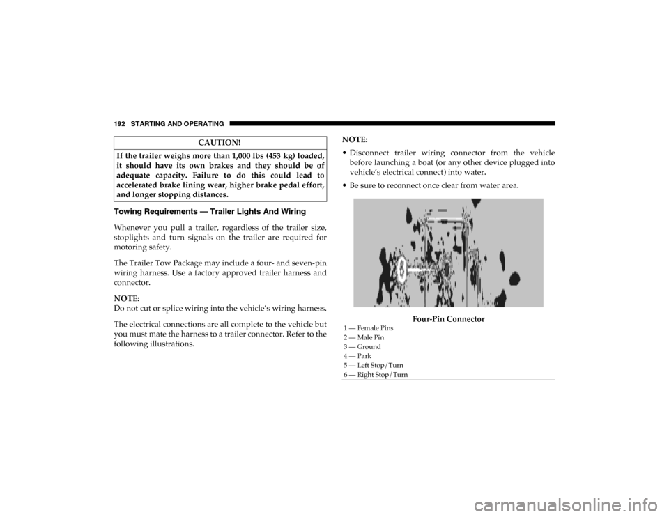
The Trailer Tow Package may include a four- and seven-pin
wiring harness. Use a factory approved trailer harness and
connector.
NOTE:
Do not cut or splice wiring into the vehicle’s wiring harness.
The electrical connections are all complete to the vehicle but
you must mate the harness to a trailer connector. Refer to the
following illustrations.NOTE:
• Disconnect trailer wiring connector from the vehicle
before launching a boat (or any other device plugged into
vehicle’s electrical connect) into water.
• Be sure to reconnect once clear from water area.
Four-Pin Connector
CAUTION!
If the trailer weighs more than 1,000 lbs (453 kg) loaded,
it should have its own brakes and they should be of
adequate capacity. Failure to do this could lead to
accelerated brake lining wear, higher brake pedal effort,
and longer stopping distances.
1 — Female Pins
2 — Male Pin
3 — Ground
4 — Park
5 — Left Stop/Turn
6 — Right Stop/Turn
2020_RAM_PROMASTER_CITY_OM_USA=GUID-7B6A7FCA-79B0-423F-95C5-ED2A949C3D13=1=en=.book Page 192