fuse RAM PROMASTER CITY 2021 Owners Manual
[x] Cancel search | Manufacturer: RAM, Model Year: 2021, Model line: PROMASTER CITY, Model: RAM PROMASTER CITY 2021Pages: 280, PDF Size: 15.78 MB
Page 6 of 280
4
MULTIMEDIA
UCONNECT SYSTEMS ..........................................86
CYBERSECURITY ..................................................86
UCONNECT SETTINGS .........................................87 Uconnect 3/3 NAV Settings ........................ 87
UCONNECT INTRODUCTION.................................97
Identifying Your Radio ................................. 97
Safety And General Information ................. 99
UCONNECT MODES ........................................... 100
Radio Mode ................................................100
Media Mode ...............................................107Phone Mode ..............................................109
NAVIGATION MODE — IF EQUIPPED ................ 121
Operating Navigation Mode —
If Equipped .................................................121
STEERING WHEEL AUDIO CONTROLS — IF
EQUIPPED ........................................................... 142
Radio Operation .........................................142
Media Mode ...............................................142
RAM TELEMATICS - IF EQUIPPED .................... 142
Ram Telematics General Information ......143
RADIO OPERATION AND MOBILE PHONES.... 143
Regulatory And Safety Information........... 144
SAFETY
SAFETY FEATURES ............................................ 145 Four-Wheel Anti-Lock Brake
System (ABS) ..............................................145 Electronic Brake Control (EBC) System ...146 AUXILIARY DRIVING SYSTEMS.........................149
Tire Pressure Monitoring
System (TPMS) ........................................... 149
OCCUPANT RESTRAINT SYSTEMS .................. 153
Occupant Restraint Systems .................... 153
Important Safety Precautions ................... 153
Seat Belt Systems ..................................... 154
Supplemental Restraint Systems (SRS)... 161
Child Restraints ......................................... 170
Transporting Pets ...................................... 184
SAFETY TIPS ....................................................... 185
Transporting Passengers .......................... 185Exhaust Gas .............................................. 185
Safety Checks You Should Make Inside
The Vehicle ................................................ 185 Periodic Safety Checks You Should Make
Outside The Vehicle ................................... 187
IN CASE OF EMERGENCY
HAZARD WARNING FLASHERS........................188
FUSES ..................................................................188
General Information .................................. 188Underhood Fuses ...................................... 189
Interior Fuses ............................................. 192
Central Unit Fuse Panel............................. 193 JACKING AND TIRE CHANGING ...................... 194
Jack Location — If Equipped ..................... 194
Removing The Spare Tire — If Equipped .. 194Preparations For Jacking ......................... 196
Jacking Instructions................................... 197
Vehicles With Alloy Wheels ....................... 200Vehicles Equipped With Wheel Covers .... 201
TIRE SERVICE KIT — IF EQUIPPED .................. 202
Tire Service Kit Storage............................. 202
Tire Service Kit Usage ............................... 202
JUMP STARTING ................................................ 204
Preparations For Jump Starting ................ 205
Jump Starting Procedure .......................... 206
IF YOUR ENGINE OVERHEATS ......................... 207
IGNITION KEY REMOVAL OVERRIDE ............... 208
GEAR SELECTOR OVERRIDE ............................ 209
FREEING A STUCK VEHICLE ............................ 209
TOWING A DISABLED VEHICLE ........................ 211
ENHANCED ACCIDENT RESPONSE SYSTEM
(EARS) ................................................................ 212
EVENT DATA RECORDER (EDR) ....................... 212
BULB REPLACEMENT ........................................ 213 Replacement Bulbs ................................... 213
Replacing Exterior Bulbs ........................... 214
Replacing Interior Bulbs ............................ 215
21_VM_OM_EN_USC_t.book Page 4
Page 38 of 280
36GETTING TO KNOW YOUR VEHICLE
If the window runs into any obstacle during
auto-closure, it will reverse direction and then
go back down. Remove the obstacle and use
the window switch again to close the window.
Power Windows System Initialization
The power windows may be reset if any of the
following occurs:
On the front doors:
Fuse or battery are disconnected when
the window is moving
50 window movements without ever
closing the window
On the rear doors (in addition to the condi -
tions for the front doors):
Fuse or battery are disconnected when
the window is moving
The auto-reverse system is activated
while the window is moving and the door
is opening
50 window movements without ever
closing the window
One door opening with the window
moving, without ever closing the door
Three door opening with the window in
motion. During these maneuvers, the
upper stop position is never reached
Proceed as follows for initialization:
1. Completely close the driver's door window, keeping the window switch pushed for at
least five seconds after the (upper) end of
travel position.
2. Proceed in the same way on the passenger's window switches.
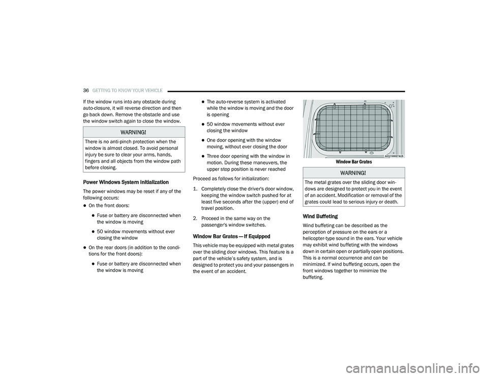
Window Bar Grates — If Equipped
This vehicle may be equipped with metal grates
over the sliding door windows. This feature is a
part of the vehicle’s safety system, and is
designed to protect you and your passengers in
the event of an accident.
Window Bar Grates
Wind Buffeting
Wind buffeting can be described as the
perception of pressure on the ears or a
helicopter-type sound in the ears. Your vehicle
may exhibit wind buffeting with the windows
down in certain open or partially open positions.
This is a normal occurrence and can be
minimized. If wind buffeting occurs, open the
front windows together to minimize the
buffeting.
WARNING!
There is no anti-pinch protection when the
window is almost closed. To avoid personal
injury be sure to clear your arms, hands,
fingers and all objects from the window path
before closing.
WARNING!
The metal grates over the sliding door win
-
dows are designed to protect you in the event
of an accident. Modification or removal of the
grates could lead to serious injury or death.
21_VM_OM_EN_USC_t.book Page 36
Page 43 of 280

GETTING TO KNOW YOUR VEHICLE41
(Continued)
(Continued)
Underhood Power Outlet Fuse Locations
ROOF RACK — IF EQUIPPED
The crossbars and siderails are designed to
carry weight on vehicles equipped with a
luggage rack. The load must not exceed 150 lbs
(68 kg), and should be uniformly distributed
over the luggage rack crossbars.
NOTE:
If not equipped with crossbars, an authorized
dealer can order and install Mopar crossbars
built specifically for this roof rack system.
Distribute cargo weight evenly on the roof rack
crossbars. The roof rack does not increase the
total load carrying capacity of the vehicle. Be
sure the total load of cargo inside the vehicle
plus that on the external rack does not exceed
the maximum vehicle load capacity.1 — #86 Fuse 15A Blue IP Power Outlet 12V (Key)
2 — #30 Fuse 15A Blue 2nd IP Power Outlet 12V
(Battery)
3 — #85 Fuse 15A Blue Rear Power Outlet 12V
(Key)
WARNING!
To avoid serious injury or death:
Only devices designed for use in this type of
outlet should be inserted into any 12 Volt
outlet.
Do not touch with wet hands.
Close the lid when not in use and while
driving the vehicle.
If this outlet is mishandled, it may cause an
electric shock and failure.
CAUTION!
Many accessories that can be plugged in
draw power from the vehicle's battery, even
when not in use (i.e., cellular phones, etc.).
Eventually, if plugged in long enough, the
vehicle's battery will discharge sufficiently
to degrade battery life and/or prevent the
engine from starting.
All accessories connected to the “battery”
powered outlets should be removed or
turned off when the vehicle is not in use.
Leaving devices connected overnight will
drain the vehicle’s battery.
Accessories that draw higher power (i.e.,
coolers, vacuum cleaners, lights, etc.) will
degrade the battery even more quickly.
Only use these intermittently and with
greater caution.
WARNING! (Continued)
After the use of high power draw accesso -
ries, or long periods of the vehicle not being
started (with accessories still plugged in),
the vehicle must be driven a sufficient
length of time to allow the generator to
recharge the vehicle's battery.
CAUTION! (Continued)
2
21_VM_OM_EN_USC_t.book Page 41
Page 190 of 280
188 (Continued)
IN CASE OF EMERGENCY
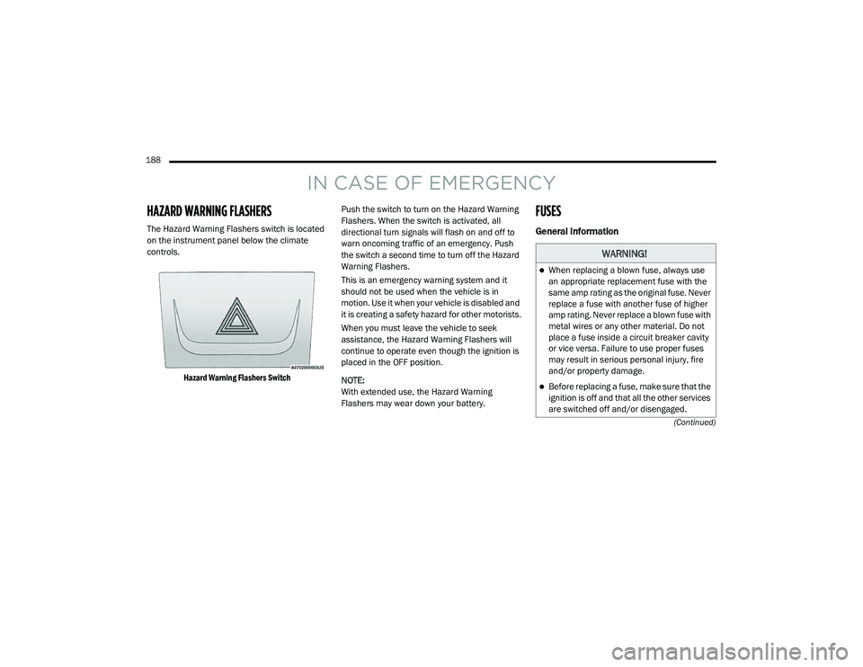
HAZARD WARNING FLASHERS
The Hazard Warning Flashers switch is located
on the instrument panel below the climate
controls.
Hazard Warning Flashers Switch
Push the switch to turn on the Hazard Warning
Flashers. When the switch is activated, all
directional turn signals will flash on and off to
warn oncoming traffic of an emergency. Push
the switch a second time to turn off the Hazard
Warning Flashers.
This is an emergency warning system and it
should not be used when the vehicle is in
motion. Use it when your vehicle is disabled and
it is creating a safety hazard for other motorists.
When you must leave the vehicle to seek
assistance, the Hazard Warning Flashers will
continue to operate even though the ignition is
placed in the OFF position.
NOTE:
With extended use, the Hazard Warning
Flashers may wear down your battery.
FUSES
General Information
WARNING!
When replacing a blown fuse, always use
an appropriate replacement fuse with the
same amp rating as the original fuse. Never
replace a fuse with another fuse of higher
amp rating. Never replace a blown fuse with
metal wires or any other material. Do not
place a fuse inside a circuit breaker cavity
or vice versa. Failure to use proper fuses
may result in serious personal injury, fire
and/or property damage.
Before replacing a fuse, make sure that the
ignition is off and that all the other services
are switched off and/or disengaged.
21_VM_OM_EN_USC_t.book Page 188
Page 191 of 280
IN CASE OF EMERGENCY189
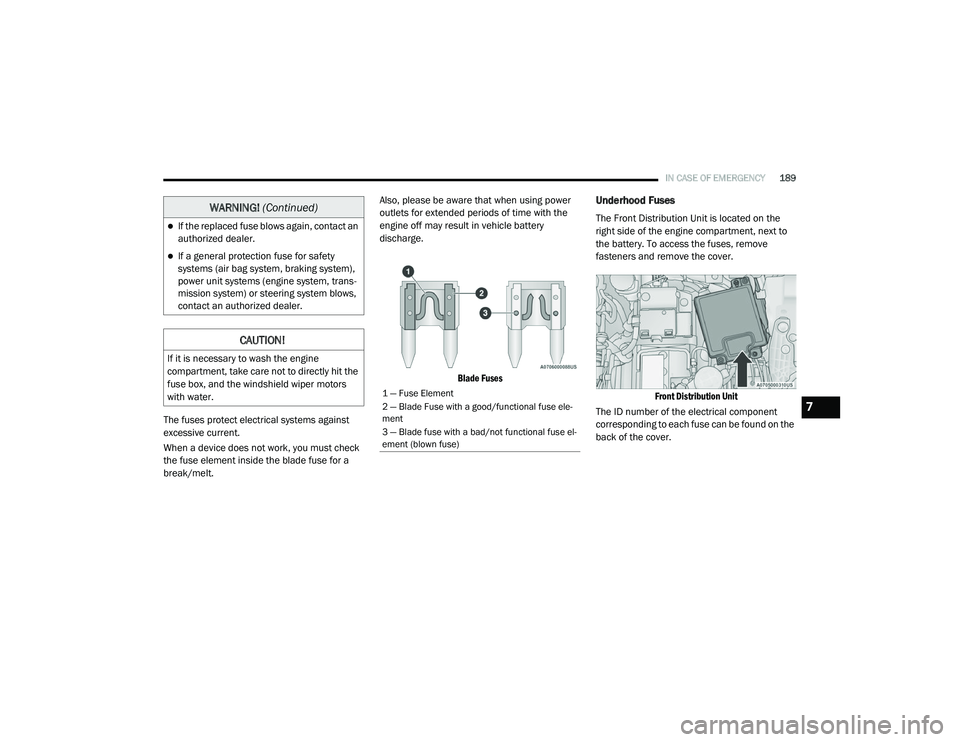
The fuses protect electrical systems against
excessive current.
When a device does not work, you must check
the fuse element inside the blade fuse for a
break/melt. Also, please be aware that when using power
outlets for extended periods of time with the
engine off may result in vehicle battery
discharge.
Blade Fuses
Underhood Fuses
The Front Distribution Unit is located on the
right side of the engine compartment, next to
the battery. To access the fuses, remove
fasteners and remove the cover.
Front Distribution Unit
The ID number of the electrical component
corresponding to each fuse can be found on the
back of the cover.If the replaced fuse blows again, contact an
authorized dealer.
If a general protection fuse for safety
systems (air bag system, braking system),
power unit systems (engine system, trans -
mission system) or steering system blows,
contact an authorized dealer.
CAUTION!
If it is necessary to wash the engine
compartment, take care not to directly hit the
fuse box, and the windshield wiper motors
with water.
WARNING! (Continued)
1 — Fuse Element
2 — Blade Fuse with a good/functional fuse ele -
ment
3 — Blade fuse with a bad/not functional fuse el -
ement (blown fuse)
7
21_VM_OM_EN_USC_t.book Page 189
Page 192 of 280
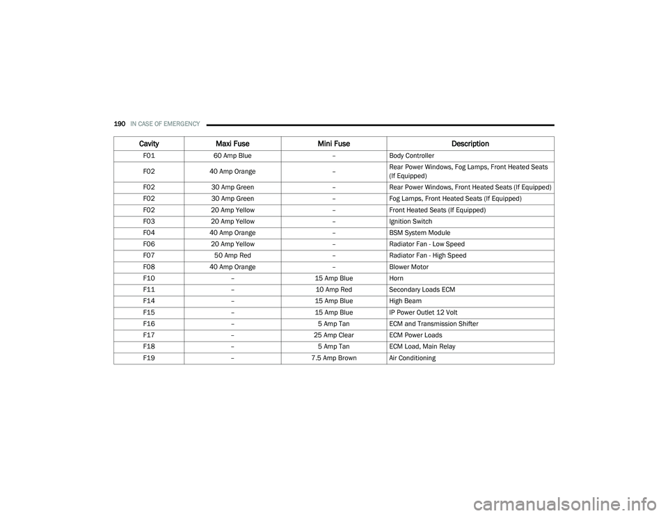
190IN CASE OF EMERGENCY
CavityMaxi Fuse Mini Fuse Description
F0160 Amp Blue –Body Controller
F02 40 Amp Orange –Rear Power Windows, Fog Lamps, Front Heated Seats
(If Equipped)
F02 30 Amp Green –Rear Power Windows, Front Heated Seats (If Equipped)
F02 30 Amp Green –Fog Lamps, Front Heated Seats (If Equipped)
F02 20 Amp Yellow –Front Heated Seats (If Equipped)
F03 20 Amp Yellow –Ignition Switch
F04 40 Amp Orange –BSM System Module
F06 20 Amp Yellow –Radiator Fan - Low Speed
F07 50 Amp Red –Radiator Fan - High Speed
F08 40 Amp Orange –Blower Motor
F10 –15 Amp BlueHorn
F11 –10 Amp RedSecondary Loads ECM
F14 –15 Amp BlueHigh Beam
F15 –15 Amp BlueIP Power Outlet 12 Volt
F16 –5 Amp TanECM and Transmission Shifter
F17 –25 Amp ClearECM Power Loads
F18 –5 Amp TanECM Load, Main Relay
F19 –7.5 Amp Brown Air Conditioning
21_VM_OM_EN_USC_t.book Page 190
Page 193 of 280
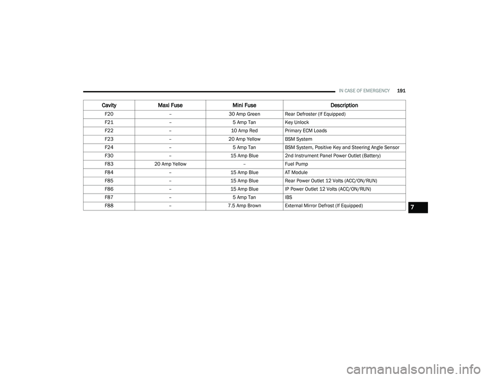
IN CASE OF EMERGENCY191
F20 –30 Amp Green Rear Defroster (If Equipped)
F21 –5 Amp TanKey Unlock
F22 –10 Amp RedPrimary ECM Loads
F23 –20 Amp Yellow BSM System
F24 –5 Amp TanBSM System, Positive Key and Steering Angle Sensor
F30 –15 Amp Blue2nd Instrument Panel Power Outlet (Battery)
F83 20 Amp Yellow –Fuel Pump
F84 –15 Amp BlueAT Module
F85 –15 Amp BlueRear Power Outlet 12 Volts (ACC/ON/RUN)
F86 –15 Amp BlueIP Power Outlet 12 Volts (ACC/ON/RUN)
F87 –5 Amp TanIBS
F88 –7.5 Amp Brown External Mirror Defrost (If Equipped)
CavityMaxi Fuse Mini Fuse Description
7
21_VM_OM_EN_USC_t.book Page 191
Page 194 of 280
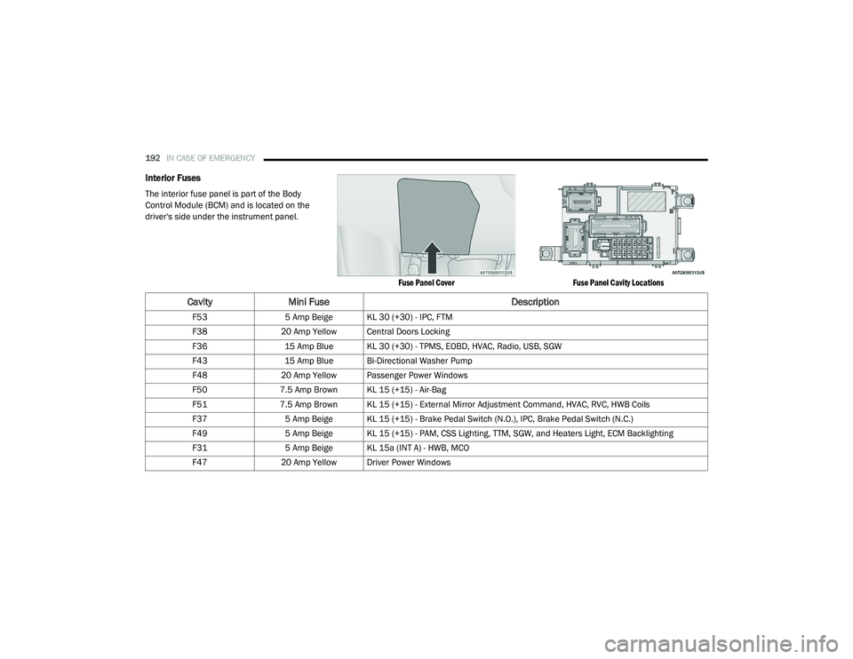
192IN CASE OF EMERGENCY
Interior Fuses
The interior fuse panel is part of the Body
Control Module (BCM) and is located on the
driver's side under the instrument panel.
Fuse Panel CoverFuse Panel Cavity Locations
CavityMini Fuse Description
F535 Amp Beige KL 30 (+30) - IPC, FTM
F38 20 Amp Yellow Central Doors Locking
F36 15 Amp Blue KL 30 (+30) - TPMS, EOBD, HVAC, Radio, USB, SGW
F43 15 Amp Blue Bi-Directional Washer Pump
F48 20 Amp Yellow Passenger Power Windows
F50 7.5 Amp Brown KL 15 (+15) - Air-Bag
F51 7.5 Amp Brown KL 15 (+15) - External Mirror Adjustment Command, HVAC, RVC, HWB Coils
F37 5 Amp Beige KL 15 (+15) - Brake Pedal Switch (N.O.), IPC, Brake Pedal Switch (N.C.)
F49 5 Amp Beige KL 15 (+15) - PAM, CSS Lighting, TTM, SGW, and Heaters Light, ECM Backlighting
F31 5 Amp Beige KL 15a (INT A) - HWB, MCO
F47 20 Amp Yellow Driver Power Windows
21_VM_OM_EN_USC_t.book Page 192
Page 195 of 280
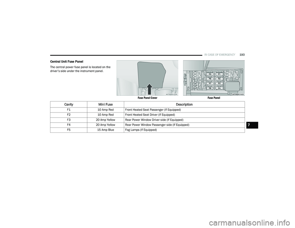
IN CASE OF EMERGENCY193
Central Unit Fuse Panel
The central power fuse panel is located on the
driver’s side under the instrument panel.
Fuse Panel CoverFuse Panel
CavityMini Fuse Description
F110 Amp Red Front Heated Seat Passenger (If Equipped)
F2 10 Amp Red Front Heated Seat Driver (If Equipped)
F3 20 Amp Yellow Rear Power Window Driver side (If Equipped)
F4 20 Amp Yellow Rear Power Window Passenger side (If Equipped)
F5 15 Amp Blue Fog Lamps (If Equipped)
7
21_VM_OM_EN_USC_t.book Page 193
Page 223 of 280
SERVICING AND MAINTENANCE221
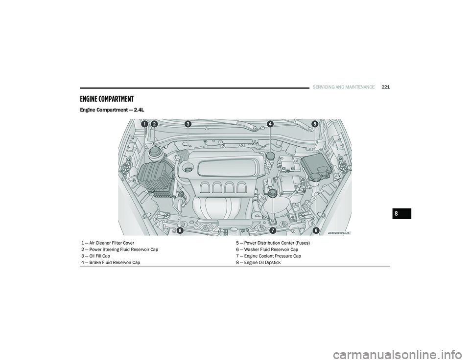
ENGINE COMPARTMENT
Engine Compartment — 2.4L
1 — Air Cleaner Filter Cover 5 — Power Distribution Center (Fuses)
2 — Power Steering Fluid Reservoir Cap 6 — Washer Fluid Reservoir Cap
3 — Oil Fill Cap 7 — Engine Coolant Pressure Cap
4 — Brake Fluid Reservoir Cap 8 — Engine Oil Dipstick
8
21_VM_OM_EN_USC_t.book Page 221