engine RAM PROMASTER CITY 2022 Service Manual
[x] Cancel search | Manufacturer: RAM, Model Year: 2022, Model line: PROMASTER CITY, Model: RAM PROMASTER CITY 2022Pages: 260, PDF Size: 8.45 MB
Page 135 of 260
SAFETY133
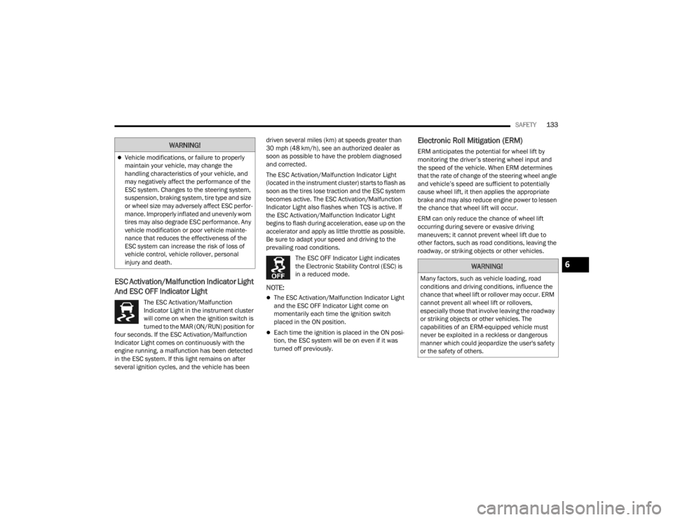
ESC Activation/Malfunction Indicator Light
And ESC OFF Indicator Light
The ESC Activation/Malfunction
Indicator Light in the instrument cluster
will come on when the ignition switch is
turned to the MAR (ON/RUN) position for
four seconds. If the ESC Activation/Malfunction
Indicator Light comes on continuously with the
engine running, a malfunction has been detected
in the ESC system. If this light remains on after
several ignition cycles, and the vehicle has been driven several miles (km) at speeds greater than
30 mph (48 km/h), see an authorized dealer as
soon as possible to have the problem diagnosed
and corrected.
The ESC Activation/Malfunction Indicator Light
(located in the instrument cluster) starts to flash as
soon as the tires lose traction and the ESC system
becomes active. The ESC Activation/Malfunction
Indicator Light also flashes when TCS is active. If
the ESC Activation/Malfunction Indicator Light
begins to flash during acceleration, ease up on the
accelerator and apply as little throttle as possible.
Be sure to adapt your speed and driving to the
prevailing road conditions.
The ESC OFF Indicator Light indicates
the Electronic Stability Control (ESC) is
in a reduced mode.
NOTE:
The ESC Activation/Malfunction Indicator Light
and the ESC OFF Indicator Light come on
momentarily each time the ignition switch
placed in the ON position.
Each time the ignition is placed in the ON posi -
tion, the ESC system will be on even if it was
turned off previously.
Electronic Roll Mitigation (ERM)
ERM anticipates the potential for wheel lift by
monitoring the driver’s steering wheel input and
the speed of the vehicle. When ERM determines
that the rate of change of the steering wheel angle
and vehicle’s speed are sufficient to potentially
cause wheel lift, it then applies the appropriate
brake and may also reduce engine power to lessen
the chance that wheel lift will occur.
ERM can only reduce the chance of wheel lift
occurring during severe or evasive driving
maneuvers; it cannot prevent wheel lift due to
other factors, such as road conditions, leaving the
roadway, or striking objects or other vehicles.Vehicle modifications, or failure to properly
maintain your vehicle, may change the
handling characteristics of your vehicle, and
may negatively affect the performance of the
ESC system. Changes to the steering system,
suspension, braking system, tire type and size
or wheel size may adversely affect ESC perfor -
mance. Improperly inflated and unevenly worn
tires may also degrade ESC performance. Any
vehicle modification or poor vehicle mainte -
nance that reduces the effectiveness of the
ESC system can increase the risk of loss of
vehicle control, vehicle rollover, personal
injury and death.
WARNING!
WARNING!
Many factors, such as vehicle loading, road
conditions and driving conditions, influence the
chance that wheel lift or rollover may occur. ERM
cannot prevent all wheel lift or rollovers,
especially those that involve leaving the roadway
or striking objects or other vehicles. The
capabilities of an ERM-equipped vehicle must
never be exploited in a reckless or dangerous
manner which could jeopardize the user's safety
or the safety of others.
6
22_VM_OM_EN_USC_t.book Page 133
Page 136 of 260

134SAFETY
Hill Start Assist (HSA)
HSA is designed to assist the driver when starting
a vehicle from a stop on a hill. HSA will maintain
the level of brake pressure the driver applied for a
short period of time after the driver takes their foot
off of the brake pedal. If the driver does not apply
the throttle during this short period of time, the
system will release brake pressure and the vehicle
will roll down the hill. The system will release brake
pressure in proportion to the amount of throttle
applied as the vehicle starts to move in the
intended direction of travel.
HSA ACTIVATION CRITERIA
The following criteria must be met in order for HSA
to activate:
The vehicle must be stopped.
The vehicle must be on a 5% (approximate)
grade or greater hill.
Gear selection matches vehicle uphill direction
(i.e., vehicle facing uphill is in forward gear;
vehicle backing uphill is in REVERSE gear).
HSA will work in REVERSE and all forward gears
when the activation criteria have been met. The
system will not activate if the vehicle is placed in
NEUTRAL or PARK.
Traction Control System (TCS)
TCS monitors the amount of wheel spin of each of
the driven wheels. If wheel spin is detected, brake
pressure is applied to the slipping wheel(s) and
engine power is reduced to provide enhanced
acceleration and stability. A feature of the TCS
system, Brake Limited Differential (BLD) functions
similarly to a limited slip differential and controls
the wheel spin across a driven axle. If one wheel on
a driven axle is spinning faster than the other, the
system will apply the brake of the spinning wheel.
This will allow more engine torque to be applied to
the wheel that is not spinning. This feature remains
active even if TCS and ESC are in the “Partial Off”
mode Ú page 132.
Trailer Sway Control (TSC) — If Equipped
TSC uses sensors in the vehicle to recognize an
excessively swaying trailer and will take the
appropriate actions to attempt to stop the sway.
The system may reduce engine power and apply
the brake of the appropriate wheel(s) to counteract
the sway of the trailer.
NOTE:TSC cannot stop all trailers from swaying. Always
use caution when towing a trailer and follow the
trailer tongue weight recommendations
Úpage 68.
When TSC is functioning, the ESC Activation/
Malfunction Indicator Light will flash, the engine
power may be reduced and you may feel the
brakes being applied to individual wheels to
attempt to stop the trailer from swaying. TSC is
disabled when the ESC system is in the “Partial
Off” mode.
WARNING!
There may be situations on minor hills with a
loaded vehicle, or while pulling a trailer, when
the system will not activate and slight rolling may
occur. This could cause a collision with another
vehicle or object. Always remember the driver is
responsible for braking the vehicle.
WARNING!
If TSC activates while driving, slow the vehicle
down, stop at the nearest safe location, and
adjust the trailer load to eliminate trailer sway.
22_VM_OM_EN_USC_t.book Page 134
Page 147 of 260
SAFETY145
(Continued)
NOTE:If the speedometer, tachometer, or any engine
related gauges are not working, the Occupant
Restraint Controller (ORC) may also be disabled. In
this condition the air bags may not be ready to
inflate for your protection. Have an authorized
dealer service the air bag system immediately.
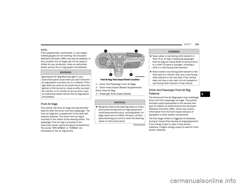
Front Air Bags
This vehicle has front air bags and lap/shoulder
belts for both the driver and front passenger. The
front air bags are a supplement to the seat belt
restraint systems. The driver front air bag is
mounted in the center of the steering wheel. The
passenger front air bag is mounted in the
instrument panel, above the glove compartment.
The words “SRS AIRBAG” or “AIRBAG” are
embossed on the air bag covers.
Front Air Bag/Knee Impact Bolster Locations
Driver And Passenger Front Air Bag
Features
The Advanced Front Air Bag system has multistage
driver and front passenger air bags. This system
provides output appropriate to the severity and
type of collision as determined by the Occupant
Restraint Controller (ORC), which may receive
information from the front impact sensors (if
equipped) or other system components.
The first stage inflator is triggered immediately
during an impact that requires air bag deployment.
A low energy output is used in less severe
collisions. A higher energy output is used for more
severe collisions.
WARNING!
Ignoring the Air Bag Warning Light in your
instrument panel could mean you won’t have the
air bag system to protect you in a collision. If the
light does not come on as a bulb check when the
ignition is first turned on, stays on after you start
the vehicle, or if it comes on as you drive, have
an authorized dealer service the air bag system
immediately.
1 — Driver And Passenger Front Air Bags
2 — Driver Knee Impact Bolster/Supplemental
Driver Knee Air Bag
3 — Passenger Knee Impact Bolster
WARNING!
Being too close to the steering wheel or instru
-
ment panel during front air bag deployment
could cause serious injury, including death. Air
bags need room to inflate. Sit back, comfort -
ably extending your arms to reach the steering
wheel or instrument panel.
Never place a rear-facing child restraint in
front of an air bag. A deploying passenger
front air bag can cause death or serious injury
to a child 12 years or younger, including a
child in a rear-facing child restraint.
Never install a rear-facing child restraint in the
front seat of a vehicle. Only use a rear-facing
child restraint in the rear seat. If the vehicle
does not have a rear seat, do not transport a
rear-facing child restraint in that vehicle.
WARNING!
6
22_VM_OM_EN_USC_t.book Page 145
Page 152 of 260

150SAFETY
NOTE:
Air bag covers may not be obvious in the interior
trim, but they will open during air bag deploy -
ment.
After any collision, the vehicle should be taken
to an authorized dealer immediately.
Enhanced Accident Response System
In the event of an impact, if the communication
network remains intact, and the power remains
intact, depending on the nature of the event, the
Occupant Restraint Controller (ORC) will determine
whether to have the Enhanced Accident Response
System perform the following functions:
Cut off fuel to the engine (if equipped)
Cut off battery power to the electric motor
(if equipped)
Flash hazard lights as long as the battery has
power
Turn on the interior lights, which remain on as
long as the battery has power or for 15 minutes
from the intervention of the Enhanced Accident
Response System
Unlock the power door locks
Your vehicle may also be designed to perform any
of these other functions in response to the
Enhanced Accident Response System:
Turn off the Fuel Filter Heater, Turn off the HVAC
Blower Motor, Close the HVAC Circulation Door
Cut off battery power to the:
Engine
Electric Motor (if equipped)
Electric Power Steering
Brake booster
Electric park brake
Automatic transmission gear selector
Horn
Front wiper
Headlamp washer pump (if equipped)
NOTE:After an accident, remember to cycle the ignition to
the STOP/OFF position and remove the key from
the ignition switch to avoid draining the battery.
Carefully check the vehicle for fuel leaks in the
engine compartment and on the ground near the
engine compartment and fuel tank before
resetting the system and starting the engine. If
there are no fuel leaks or damage to the vehicle
electrical devices (e.g. headlights) after an
accident, reset the system by following the
procedure described below. If you have any doubt,
contact an authorized dealer.
Enhanced Accident Response System
Reset Procedure
In order to reset the Enhanced Accident Response
System functions after an event, the ignition switch
must be changed from ignition AVV/START or
MAR/RUN to ignition STOP/OFF. Carefully check
the vehicle for fuel leaks in the engine
compartment and on the ground near the engine
compartment and fuel tank before resetting the
system and starting the engine. After an accident,
if the vehicle will not start after performing the
reset procedure, the vehicle must be towed to an
authorized dealer to be inspected and to have the
Enhanced Accident Response System reset.
WARNING!
Deployed air bags and seat belt pretensioners
cannot protect you in another collision. Have the
air bags, seat belt pretensioners, and the seat
belt retractor assemblies replaced by an
authorized dealer immediately. Also, have the
Occupant Restraint Controller System serviced
as well.
22_VM_OM_EN_USC_t.book Page 150
Page 171 of 260
SAFETY169
(Continued)
(Continued)
PERIODIC SAFETY CHECKS YOU SHOULD
M
AKE OUTSIDE THE VEHICLE
Tires
Examine tires for excessive tread wear and uneven
wear patterns. Check for stones, nails, glass, or
other objects lodged in the tread or sidewall.
Inspect the tread for cuts and cracks. Inspect
sidewalls for cuts, cracks, and bulges. Check the
lug nut/bold torque for tightness. Check the tires
(including spare) for proper cold inflation pressure.
WARNING!
An improperly attached, damaged, folded, or
stacked floor mat, or damaged floor mat
fasteners may cause your floor mat to interfere
with the accelerator, brake, or clutch pedals and
cause a loss of vehicle control. To prevent
SERIOUS INJURY or DEATH:
ALWAYS securely attach your floor
mat using the floor mat fasteners. DO
NOT install your floor mat upside down
or turn your floor mat over. Lightly pull
to confirm mat is secured using the floor mat
fasteners on a regular basis.
ALWAYS REMOVE THE EXISTING
FLOOR MAT FROM THE VEHICLE
before installing any other floor mat.
NEVER install or stack an additional
floor mat on top of an existing floor mat.
ONLY install floor mats designed to fit your
vehicle. NEVER install a floor mat that cannot
be properly attached and secured to your
vehicle. If a floor mat needs to be replaced,
only use a FCA approved floor mat for the
specific make, model, and year of your
vehicle.
ONLY use the driver’s side floor mat on the
driver’s side floor area. To check for interfer -
ence, with the vehicle properly parked with the
engine off, fully depress the accelerator, the
brake, and the clutch pedal (if present) to
check for interference. If your floor mat inter -
feres with the operation of any pedal, or is not
secure to the floor, remove the floor mat from
the vehicle and place the floor mat in your
trunk.
ONLY use the passenger’s side floor mat on
the passenger’s side floor area.
ALWAYS make sure objects cannot fall or slide
into the driver’s side floor area when the
vehicle is moving. Objects can become
trapped under accelerator, brake, or clutch
pedals and could cause a loss of vehicle
control.
NEVER place any objects under the floor mat
(e.g., towels, keys, etc.). These objects could
change the position of the floor mat and may
cause interference with the accelerator,
brake, or clutch pedals.
WARNING!
If the vehicle carpet has been removed and
re-installed, always properly attach carpet to
the floor and check the floor mat fasteners are
secure to the vehicle carpet. Fully depress
each pedal to check for interference with the
accelerator, brake, or clutch pedals then
re-install the floor mats.
It is recommended to only use mild soap and
water to clean your floor mats. After cleaning,
always check your floor mat has been properly
installed and is secured to your vehicle using
the floor mat fasteners by lightly pulling mat.
WARNING!
6
22_VM_OM_EN_USC_t.book Page 169
Page 172 of 260
170SAFETY
(Continued)
Lights
Have someone observe the operation of brake
lights and exterior lights while you work the
controls. Check turn signal and high beam
indicator lights on the instrument panel.
Door Latches
Check for proper closing, latching, and locking.
Fluid Leaks
Check area under the vehicle after overnight
parking for fuel, coolant, oil, or other fluid leaks.
Also, if gasoline fumes are detected or if fuel or
brake fluid leaks are suspected, the cause should
be located and corrected immediately.
EXHAUST GAS
The best protection against carbon monoxide entry
into the vehicle body is a properly maintained
engine exhaust system.
Whenever a change is noticed in the sound of the
exhaust system, when exhaust fumes can be
detected inside the vehicle, or when the underside
or rear of the vehicle is damaged, have an
authorized dealer inspect the complete exhaust
system and adjacent body areas for broken,
damaged, deteriorated, or mispositioned parts.
Open seams or loose connections could permit
exhaust fumes to seep into the passenger
compartment. In addition, inspect the exhaust
system each time the vehicle is raised for
lubrication or oil change. Replace as required.
CARBON MONOXIDE WARNINGS
WARNING!
Exhaust gases can injure or kill. They contain
carbon monoxide (CO), which is colorless and
odorless. Breathing it can make you
unconscious and can eventually poison you. To
avoid breathing (CO), follow these safety tips:
Do not run the engine in a closed garage or in
confined areas any longer than needed to
move your vehicle in or out of the area.
If you are required to drive with the trunk/lift -
gate/rear doors open, make sure that all
windows are closed and the climate control
BLOWER switch is set at high speed. DO NOT
use the recirculation mode.
If it is necessary to sit in a parked vehicle with
the engine running, adjust your heating or
cooling controls to force outside air into the
vehicle. Set the blower at high speed.
WARNING!
WARNING!
Carbon monoxide (CO) in exhaust gases is
deadly. Follow the precautions below to prevent
carbon monoxide poisoning:
Do not inhale exhaust gases. They contain
carbon monoxide, a colorless and odorless
gas, which can kill. Never run the engine in a
closed area, such as a garage, and never sit in
a parked vehicle with the engine running for
an extended period. If the vehicle is stopped in
an open area with the engine running for more
than a short period, adjust the ventilation
system to force fresh, outside air into the
vehicle.
Guard against carbon monoxide with proper
maintenance. Have the exhaust system
inspected every time the vehicle is raised.
Have any abnormal conditions repaired
promptly. Until repaired, drive with all side
windows fully open.
22_VM_OM_EN_USC_t.book Page 170
Page 173 of 260
171
(Continued)
IN CASE OF EMERGENCY
HAZARD WARNING FLASHERS
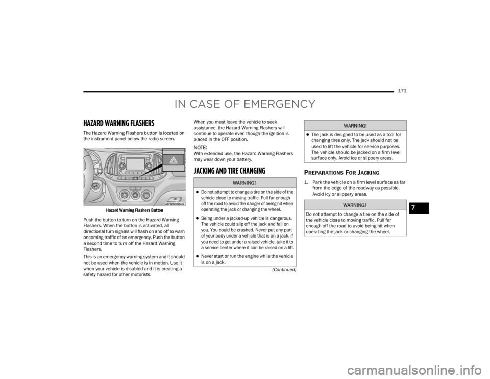
The Hazard Warning Flashers button is located on
the instrument panel below the radio screen.
Hazard Warning Flashers Button
Push the button to turn on the Hazard Warning
Flashers. When the button is activated, all
directional turn signals will flash on and off to warn
oncoming traffic of an emergency. Push the button
a second time to turn off the Hazard Warning
Flashers.
This is an emergency warning system and it should
not be used when the vehicle is in motion. Use it
when your vehicle is disabled and it is creating a
safety hazard for other motorists. When you must leave the vehicle to seek
assistance, the Hazard Warning Flashers will
continue to operate even though the ignition is
placed in the OFF position.
NOTE:With extended use, the Hazard Warning Flashers
may wear down your battery.
JACKING AND TIRE CHANGING PREPARATIONS FOR JACKING
1. Park the vehicle on a firm level surface as far
from the edge of the roadway as possible.
Avoid icy or slippery areas.
WARNING!
Do not attempt to change a tire on the side of the
vehicle close to moving traffic. Pull far enough
off the road to avoid the danger of being hit when
operating the jack or changing the wheel.
Being under a jacked-up vehicle is dangerous.
The vehicle could slip off the jack and fall on
you. You could be crushed. Never put any part
of your body under a vehicle that is on a jack. If
you need to get under a raised vehicle, take it to
a service center where it can be raised on a lift.
Never start or run the engine while the vehicle
is on a jack.
The jack is designed to be used as a tool for
changing tires only. The jack should not be
used to lift the vehicle for service purposes.
The vehicle should be jacked on a firm level
surface only. Avoid ice or slippery areas.
WARNING!
Do not attempt to change a tire on the side of
the vehicle close to moving traffic. Pull far
enough off the road to avoid being hit when
operating the jack or changing the wheel.
WARNING!
7
22_VM_OM_EN_USC_t.book Page 171
Page 176 of 260
174IN CASE OF EMERGENCY
(Continued)
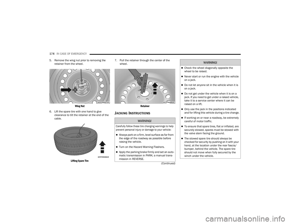
5. Remove the wing nut prior to removing the
retainer from the wheel.
Wing Nut
6. Lift the spare tire with one hand to give clearance to tilt the retainer at the end of the
cable.
Lifting Spare Tire
7. Pull the retainer through the center of the
wheel.
Retainer
JACKING INSTRUCTIONS
WARNING!
Carefully follow these tire changing warnings to help
prevent personal injury or damage to your vehicle:
Always park on a firm, level surface as far from
the edge of the roadway as possible before
raising the vehicle.
Turn on the Hazard Warning Flashers.
Apply the parking brake firmly and set an auto -
matic transmission in PARK; a manual trans -
mission in REVERSE.
Chock the wheel diagonally opposite the
wheel to be raised.
Never start or run the engine with the vehicle
on a jack.
Do not let anyone sit in the vehicle when it is
on a jack.
Do not get under the vehicle when it is on a
jack. If you need to get under a raised vehicle,
take it to a service center where it can be
raised on a lift.
Only use the jack in the positions indicated
and for lifting this vehicle during a tire change.
If working on or near a roadway, be extremely
careful of motor traffic.
To ensure that spare tires, flat or inflated, are
securely stowed, spares must be stowed with
the valve stem facing the ground.
The stowed spare tire should always be
checked for security by pushing on it with your
hand, at the location under the rear fascia/
bumper, behind the vehicle. The spare tire
should not move when fully secured by the
winch under the vehicle.
WARNING!
22_VM_OM_EN_USC_t.book Page 174
Page 182 of 260
180IN CASE OF EMERGENCY
Insert the power plug into the vehicle power outlet
socket. Start the vehicle engine. Push the Tire Service Kit power button on. The
electric compressor will be turned on, sealant and
air will inflate the tire.
Minimum 26 psi (1.8 bar) of pressure should be
reached within 20 minutes. If the pressure has not
been reached, turn off and remove the Tire Service
Kit, drive the vehicle 30 feet (10 meters) back and
forth, to better distribute the sealant inside the
tire.
Attach the clear flexible filling tube of the
compressor directly to the tire valve and repeat the
inflation process.
When the correct pressure has been reached,
start driving the vehicle to uniformly distribute the
sealant inside the tire. After 10 minutes, stop and
check the tire pressure. If the pressure is below
19 psi (1.3 bar), do not drive the vehicle, as the
tire is too damaged, contact the nearest
authorized dealer.
If the pressure is at 19 psi (1.3 bar) or above
repeat the inflation process to reach the correct
tire pressure and continue driving.
Peel off the warning label from the bottle and place
it on the dashboard as a reminder to the driver that
a tire has been treated with Tire Service Kit.
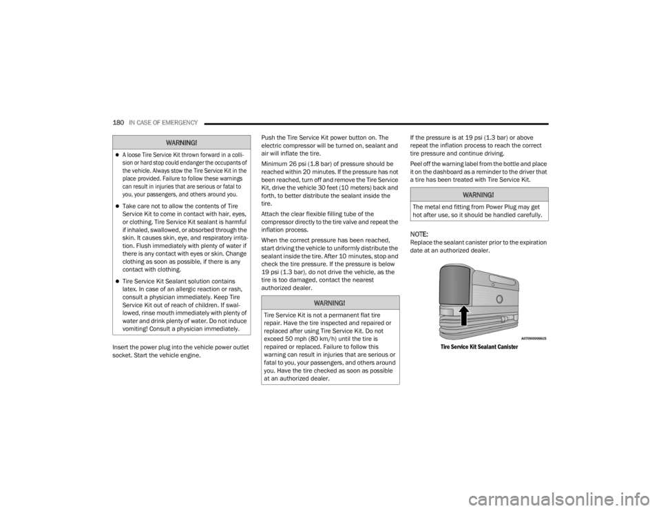
NOTE:Replace the sealant canister prior to the expiration
date at an authorized dealer.
Tire Service Kit Sealant Canister
A loose Tire Service Kit thrown forward in a colli -
sion or hard stop could endanger the occupants of
the vehicle. Always stow the Tire Service Kit in the
place provided. Failure to follow these warnings
can result in injuries that are serious or fatal to
you, your passengers, and others around you.
Take care not to allow the contents of Tire
Service Kit to come in contact with hair, eyes,
or clothing. Tire Service Kit sealant is harmful
if inhaled, swallowed, or absorbed through the
skin. It causes skin, eye, and respiratory irrita -
tion. Flush immediately with plenty of water if
there is any contact with eyes or skin. Change
clothing as soon as possible, if there is any
contact with clothing.
Tire Service Kit Sealant solution contains
latex. In case of an allergic reaction or rash,
consult a physician immediately. Keep Tire
Service Kit out of reach of children. If swal -
lowed, rinse mouth immediately with plenty of
water and drink plenty of water. Do not induce
vomiting! Consult a physician immediately.
WARNING!
WARNING!
Tire Service Kit is not a permanent flat tire
repair. Have the tire inspected and repaired or
replaced after using Tire Service Kit. Do not
exceed 50 mph (80 km/h) until the tire is
repaired or replaced. Failure to follow this
warning can result in injuries that are serious or
fatal to you, your passengers, and others around
you. Have the tire checked as soon as possible
at an authorized dealer.
WARNING!
The metal end fitting from Power Plug may get
hot after use, so it should be handled carefully.
22_VM_OM_EN_USC_t.book Page 180
Page 183 of 260
IN CASE OF EMERGENCY181
JUMP STARTING
If your vehicle has a discharged battery, it can be
jump started using a set of jumper cables and a
battery in another vehicle or by using a portable
battery booster pack. Jump starting can be
dangerous if done improperly, so please follow the
procedures in this section carefully.
NOTE:When using a portable battery booster pack, follow
the manufacturer’s operating instructions and
precautions.
PREPARATIONS FOR JUMP STARTING
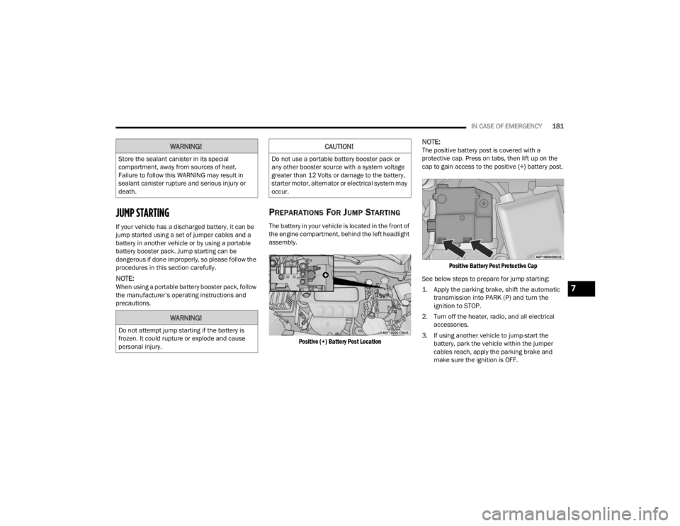
The battery in your vehicle is located in the front of
the engine compartment, behind the left headlight
assembly.
Positive (+) Battery Post Location
NOTE:The positive battery post is covered with a
protective cap. Press on tabs, then lift up on the
cap to gain access to the positive (+) battery post.
Positive Battery Post Protective Cap
See below steps to prepare for jump starting:
1. Apply the parking brake, shift the automatic transmission into PARK (P) and turn the
ignition to STOP.
2. Turn off the heater, radio, and all electrical accessories.
3. If using another vehicle to jump-start the battery, park the vehicle within the jumper
cables reach, apply the parking brake and
make sure the ignition is OFF.WARNING!
Store the sealant canister in its special
compartment, away from sources of heat.
Failure to follow this WARNING may result in
sealant canister rupture and serious injury or
death.
WARNING!
Do not attempt jump starting if the battery is
frozen. It could rupture or explode and cause
personal injury.
CAUTION!
Do not use a portable battery booster pack or
any other booster source with a system voltage
greater than 12 Volts or damage to the battery,
starter motor, alternator or electrical system may
occur.
7
22_VM_OM_EN_USC_t.book Page 181