air condition RAM PROMASTER CITY 2022 Owners Manual
[x] Cancel search | Manufacturer: RAM, Model Year: 2022, Model line: PROMASTER CITY, Model: RAM PROMASTER CITY 2022Pages: 260, PDF Size: 8.45 MB
Page 7 of 260
5
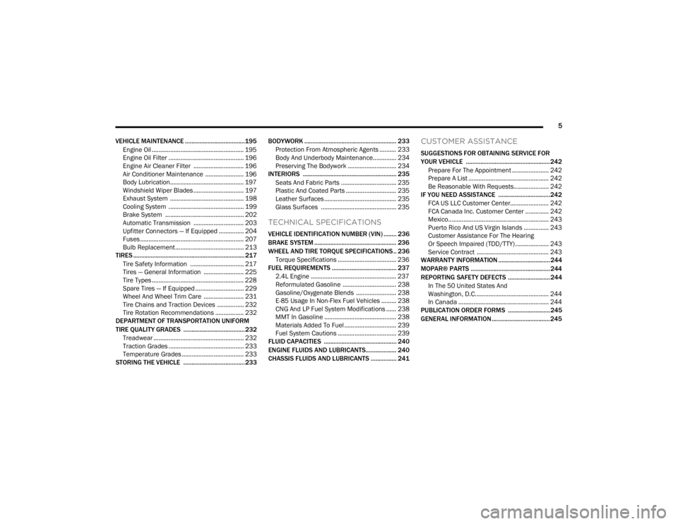
VEHICLE MAINTENANCE ..................................... 195 Engine Oil ....................................................... 195
Engine Oil Filter ............................................. 196
Engine Air Cleaner Filter .............................. 196Air Conditioner Maintenance ....................... 196
Body Lubrication............................................ 197
Windshield Wiper Blades .............................. 197Exhaust System ............................................ 198
Cooling System ............................................. 199
Brake System ............................................... 202
Automatic Transmission .............................. 203Upfitter Connectors — If Equipped ............... 204
Fuses.............................................................. 207
Bulb Replacement ......................................... 213
TIRES ..................................................................... 217
Tire Safety Information ................................ 217
Tires — General Information ........................ 225
Tire Types ....................................................... 228
Spare Tires — If Equipped ............................. 229
Wheel And Wheel Trim Care ........................ 231
Tire Chains and Traction Devices ................ 232
Tire Rotation Recommendations ................. 232
DEPARTMENT OF TRANSPORTATION UNIFORM
TIRE QUALITY GRADES ...................................... 232
Treadwear ...................................................... 232Traction Grades ............................................. 233
Temperature Grades ..................................... 233
STORING THE VEHICLE ...................................... 233 BODYWORK ......................................................... 233
Protection From Atmospheric Agents .......... 233
Body And Underbody Maintenance.............. 234Preserving The Bodywork ............................. 234
INTERIORS .......................................................... 235
Seats And Fabric Parts ................................. 235
Plastic And Coated Parts .............................. 235Leather Surfaces ........................................... 235Glass Surfaces ............................................. 235
TECHNICAL SPECIFICATIONS
VEHICLE IDENTIFICATION NUMBER (VIN) ........ 236
BRAKE SYSTEM ................................................... 236
WHEEL AND TIRE TORQUE SPECIFICATIONS .. 236
Torque Specifications ................................... 236
FUEL REQUIREMENTS ........................................ 237
2.4L Engine ................................................... 237
Reformulated Gasoline ................................ 238Gasoline/Oxygenate Blends ........................ 238
E-85 Usage In Non-Flex Fuel Vehicles ......... 238CNG And LP Fuel System Modifications ...... 238MMT In Gasoline ........................................... 238Materials Added To Fuel ............................... 239
Fuel System Cautions ................................... 239
FLUID CAPACITIES ............................................. 240
ENGINE FLUIDS AND LUBRICANTS................... 240
CHASSIS FLUIDS AND LUBRICANTS ................ 241
CUSTOMER ASSISTANCE
SUGGESTIONS FOR OBTAINING SERVICE FOR
YOUR VEHICLE .................................................... 242
Prepare For The Appointment ...................... 242
Prepare A List ................................................ 242
Be Reasonable With Requests..................... 242
IF YOU NEED ASSISTANCE ................................ 242
FCA US LLC Customer Center....................... 242
FCA Canada Inc. Customer Center .............. 242
Mexico............................................................ 243
Puerto Rico And US Virgin Islands ............... 243
Customer Assistance For The Hearing
Or Speech Impaired (TDD/TTY) .................... 243
Service Contract ........................................... 243
WARRANTY INFORMATION ................................ 244
MOPAR® PARTS ................................................. 244
REPORTING SAFETY DEFECTS .......................... 244
In The 50 United States And
Washington, D.C............................................ 244
In Canada ...................................................... 244
PUBLICATION ORDER FORMS .......................... 245
GENERAL INFORMATION.................................... 245
22_VM_OM_EN_USC_t.book Page 5
Page 30 of 260
28GETTING TO KNOW YOUR VEHICLE
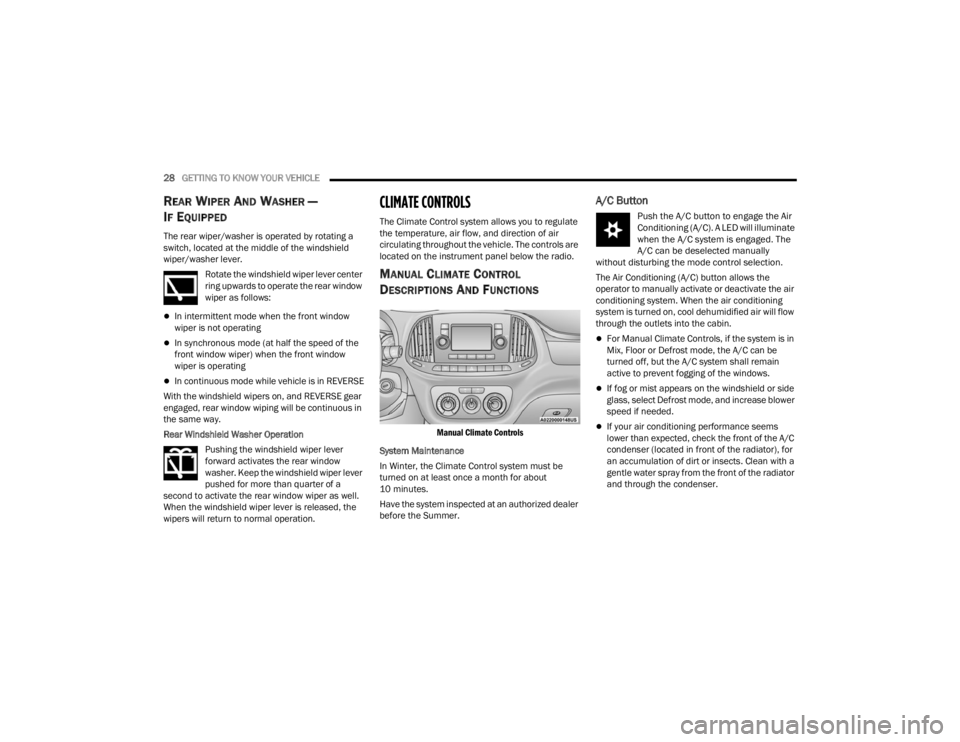
REAR WIPER AND WASHER —
I
F EQUIPPED
The rear wiper/washer is operated by rotating a
switch, located at the middle of the windshield
wiper/washer lever.
Rotate the windshield wiper lever center
ring upwards to operate the rear window
wiper as follows:
In intermittent mode when the front window
wiper is not operating
In synchronous mode (at half the speed of the
front window wiper) when the front window
wiper is operating
In continuous mode while vehicle is in REVERSE
With the windshield wipers on, and REVERSE gear
engaged, rear window wiping will be continuous in
the same way.
Rear Windshield Washer Operation Pushing the windshield wiper lever
forward activates the rear window
washer. Keep the windshield wiper lever
pushed for more than quarter of a
second to activate the rear window wiper as well.
When the windshield wiper lever is released, the
wipers will return to normal operation.
CLIMATE CONTROLS
The Climate Control system allows you to regulate
the temperature, air flow, and direction of air
circulating throughout the vehicle. The controls are
located on the instrument panel below the radio.
MANUAL CLIMATE CONTROL
D
ESCRIPTIONS AND FUNCTIONS
Manual Climate Controls
System Maintenance
In Winter, the Climate Control system must be
turned on at least once a month for about
10 minutes.
Have the system inspected at an authorized dealer
before the Summer.
A/C Button
Push the A/C button to engage the Air
Conditioning (A/C). A LED will illuminate
when the A/C system is engaged. The
A/C can be deselected manually
without disturbing the mode control selection.
The Air Conditioning (A/C) button allows the
operator to manually activate or deactivate the air
conditioning system. When the air conditioning
system is turned on, cool dehumidified air will flow
through the outlets into the cabin.
For Manual Climate Controls, if the system is in
Mix, Floor or Defrost mode, the A/C can be
turned off, but the A/C system shall remain
active to prevent fogging of the windows.
If fog or mist appears on the windshield or side
glass, select Defrost mode, and increase blower
speed if needed.
If your air conditioning performance seems
lower than expected, check the front of the A/C
condenser (located in front of the radiator), for
an accumulation of dirt or insects. Clean with a
gentle water spray from the front of the radiator
and through the condenser.
22_VM_OM_EN_USC_t.book Page 28
Page 31 of 260
GETTING TO KNOW YOUR VEHICLE29
(Continued)
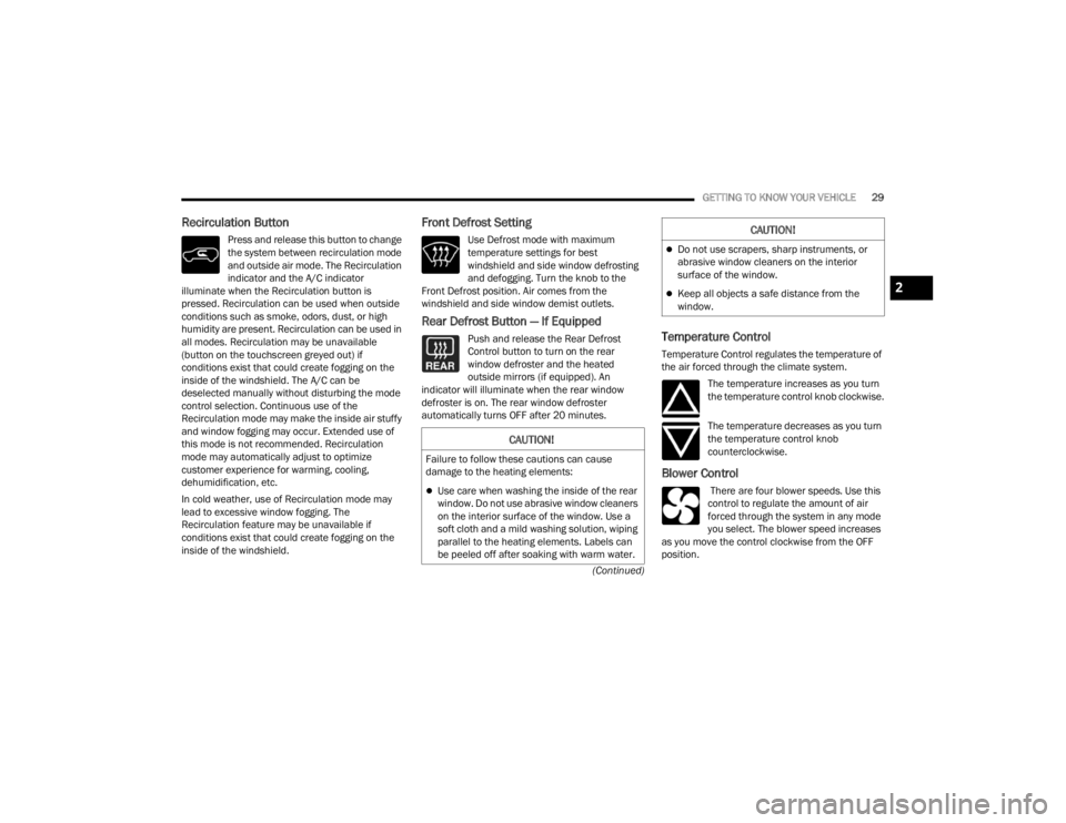
Recirculation Button
Press and release this button to change
the system between recirculation mode
and outside air mode. The Recirculation
indicator and the A/C indicator
illuminate when the Recirculation button is
pressed. Recirculation can be used when outside
conditions such as smoke, odors, dust, or high
humidity are present. Recirculation can be used in
all modes. Recirculation may be unavailable
(button on the touchscreen greyed out) if
conditions exist that could create fogging on the
inside of the windshield. The A/C can be
deselected manually without disturbing the mode
control selection. Continuous use of the
Recirculation mode may make the inside air stuffy
and window fogging may occur. Extended use of
this mode is not recommended. Recirculation
mode may automatically adjust to optimize
customer experience for warming, cooling,
dehumidification, etc.
In cold weather, use of Recirculation mode may
lead to excessive window fogging. The
Recirculation feature may be unavailable if
conditions exist that could create fogging on the
inside of the windshield.
Front Defrost Setting
Use Defrost mode with maximum
temperature settings for best
windshield and side window defrosting
and defogging. Turn the knob to the
Front Defrost position. Air comes from the
windshield and side window demist outlets.
Rear Defrost Button — If Equipped
Push and release the Rear Defrost
Control button to turn on the rear
window defroster and the heated
outside mirrors (if equipped). An
indicator will illuminate when the rear window
defroster is on. The rear window defroster
automatically turns OFF after 20 minutes.Temperature Control
Temperature Control regulates the temperature of
the air forced through the climate system.
The temperature increases as you turn
the temperature control knob clockwise.
The temperature decreases as you turn
the temperature control knob
counterclockwise.
Blower Control
There are four blower speeds. Use this
control to regulate the amount of air
forced through the system in any mode
you select. The blower speed increases
as you move the control clockwise from the OFF
position.
CAUTION!
Failure to follow these cautions can cause
damage to the heating elements:
Use care when washing the inside of the rear
window. Do not use abrasive window cleaners
on the interior surface of the window. Use a
soft cloth and a mild washing solution, wiping
parallel to the heating elements. Labels can
be peeled off after soaking with warm water.
Do not use scrapers, sharp instruments, or
abrasive window cleaners on the interior
surface of the window.
Keep all objects a safe distance from the
window.
CAUTION!
2
22_VM_OM_EN_USC_t.book Page 29
Page 32 of 260
30GETTING TO KNOW YOUR VEHICLE
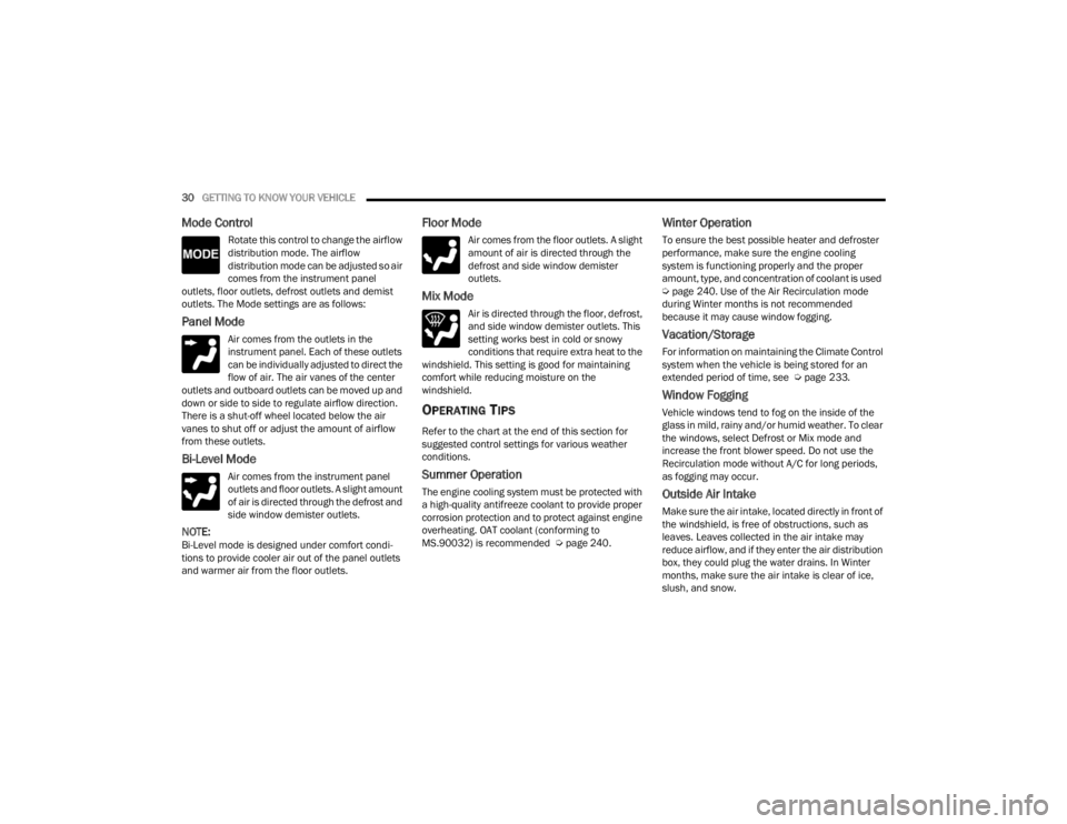
Mode Control
Rotate this control to change the airflow
distribution mode. The airflow
distribution mode can be adjusted so air
comes from the instrument panel
outlets, floor outlets, defrost outlets and demist
outlets. The Mode settings are as follows:
Panel Mode
Air comes from the outlets in the
instrument panel. Each of these outlets
can be individually adjusted to direct the
flow of air. The air vanes of the center
outlets and outboard outlets can be moved up and
down or side to side to regulate airflow direction.
There is a shut-off wheel located below the air
vanes to shut off or adjust the amount of airflow
from these outlets.
Bi-Level Mode
Air comes from the instrument panel
outlets and floor outlets. A slight amount
of air is directed through the defrost and
side window demister outlets.
NOTE:Bi-Level mode is designed under comfort condi -
tions to provide cooler air out of the panel outlets
and warmer air from the floor outlets.
Floor Mode
Air comes from the floor outlets. A slight
amount of air is directed through the
defrost and side window demister
outlets.
Mix Mode
Air is directed through the floor, defrost,
and side window demister outlets. This
setting works best in cold or snowy
conditions that require extra heat to the
windshield. This setting is good for maintaining
comfort while reducing moisture on the
windshield.
OPERATING TIPS
Refer to the chart at the end of this section for
suggested control settings for various weather
conditions.
Summer Operation
The engine cooling system must be protected with
a high-quality antifreeze coolant to provide proper
corrosion protection and to protect against engine
overheating. OAT coolant (conforming to
MS.90032) is recommended Ú page 240.
Winter Operation
To ensure the best possible heater and defroster
performance, make sure the engine cooling
system is functioning properly and the proper
amount, type, and concentration of coolant is used
Úpage 240. Use of the Air Recirculation mode
during Winter months is not recommended
because it may cause window fogging.
Vacation/Storage
For information on maintaining the Climate Control
system when the vehicle is being stored for an
extended period of time, see Ú page 233.
Window Fogging
Vehicle windows tend to fog on the inside of the
glass in mild, rainy and/or humid weather. To clear
the windows, select Defrost or Mix mode and
increase the front blower speed. Do not use the
Recirculation mode without A/C for long periods,
as fogging may occur.
Outside Air Intake
Make sure the air intake, located directly in front of
the windshield, is free of obstructions, such as
leaves. Leaves collected in the air intake may
reduce airflow, and if they enter the air distribution
box, they could plug the water drains. In Winter
months, make sure the air intake is clear of ice,
slush, and snow.
22_VM_OM_EN_USC_t.book Page 30
Page 33 of 260
GETTING TO KNOW YOUR VEHICLE31
Cabin Air Filter
The Climate Control system filters out dust and
pollen from the air. Contact an authorized dealer to
service your cabin air filter, and to have it replaced
when needed.
Operating Tips Chart
INTERIOR STORAGE AND EQUIPMENT
STORAGE
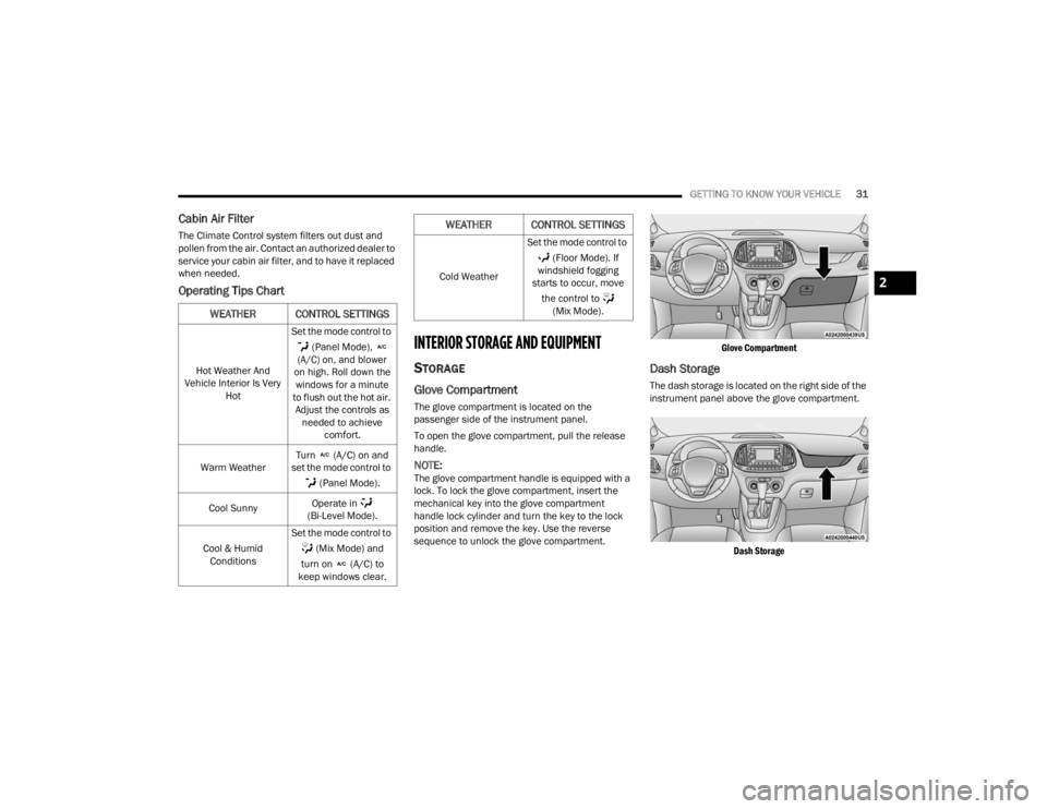
Glove Compartment
The glove compartment is located on the
passenger side of the instrument panel.
To open the glove compartment, pull the release
handle.
NOTE:The glove compartment handle is equipped with a
lock. To lock the glove compartment, insert the
mechanical key into the glove compartment
handle lock cylinder and turn the key to the lock
position and remove the key. Use the reverse
sequence to unlock the glove compartment.
Glove Compartment
Dash Storage
The dash storage is located on the right side of the
instrument panel above the glove compartment.
Dash Storage
WEATHER CONTROL SETTINGS
Hot Weather And
Vehicle Interior Is Very Hot Set the mode control to
(Panel Mode),
(A/C) on, and blower
on high. Roll down the windows for a minute
to flush out the hot air. Adjust the controls as needed to achieve comfort.
Warm Weather Turn (A/C) on and
set the mode control to
(Panel Mode).
Cool Sunny Operate in
(Bi-Level Mode).
Cool & Humid Conditions Set the mode control to
(Mix Mode) and
turn on (A/C) to
keep windows clear.
Cold Weather Set the mode control to
(Floor Mode). If
windshield fogging
starts to occur, move
the control to (Mix Mode).
WEATHER CONTROL SETTINGS
2
22_VM_OM_EN_USC_t.book Page 31
Page 42 of 260
40GETTING TO KNOW YOUR INSTRUMENT PANEL
INSTRUMENT CLUSTER DESCRIPTIONS
1. Speedometer
Indicates vehicle speed.
2. Fuel Gauge
The pointer shows the level of fuel in the
fuel tank when the ignition switch is in the
ON/RUN position.
The fuel pump arrow symbol
points to the side of the vehicle
where the fuel door is located.
3.Temperature Gauge
The temperature gauge shows engine
coolant temperature. Any reading within the
normal range indicates that the engine
cooling system is operating satisfactorily.
The pointer will likely indicate a higher
temperature when driving in hot weather or
up mountain grades. It should not be
allowed to exceed the upper limits of the
normal operating range. 4. Tachometer
Indicates the engine speed in revolutions
per minute (RPM x 1000).
5. Instrument Cluster Display
When the appropriate conditions exist, this
display shows the instrument cluster
display messages Ú page 40.
INSTRUMENT CLUSTER DISPLAY
Your vehicle will be equipped with an instrument
cluster display, which offers useful information to
the driver. With the ignition in the OFF mode,
opening/closing of a door will activate the display
for viewing, and display the total miles, or
kilometers, in the odometer. The steering wheel
mounted controls allow you to scroll through the
main menus and submenus. You can access the
specific information you want and make selections
and adjustments.
LOCATION AND CONTROLS
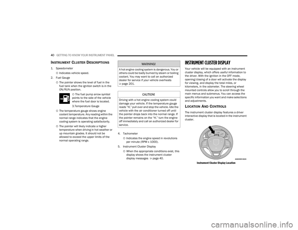
The instrument cluster display features a driver
interactive display that is located in the instrument
cluster.
Instrument Cluster Display Location
WARNING!
A hot engine cooling system is dangerous. You or
others could be badly burned by steam or boiling
coolant. You may want to call an authorized
dealer for service if your vehicle overheats
Úpage 201.
CAUTION!
Driving with a hot engine cooling system could
damage your vehicle. If the temperature gauge
reads “H,” pull over and stop the vehicle. Idle the
vehicle with the air conditioner turned off until
the pointer drops back into the normal range. If
the pointer remains on the “H,” turn the engine
off immediately and call an authorized dealer for
service.
22_VM_OM_EN_USC_t.book Page 40
Page 46 of 260
44GETTING TO KNOW YOUR INSTRUMENT PANEL
“Trip B” can be used to display the figures relating to:
Trip distance B
Average Economy B
Average speed B
Travel time B (driving time)
NOTE:“Trip B” functions may be excluded (see “Trip B
Data”). Range and Instantaneous Economy cannot
be reset.
VALUES DISPLAYED
Range
This indicates the distance which may be traveled
with the fuel remaining in the tank, assuming that
driving conditions will not change. The message “----”
will appear on the display in the following cases:
Distance less than 30 miles (or 50 km).
The vehicle is parked for a long time with the
engine running.
NOTE:The range depends on several factors: driving
style, type of route (freeway, residential, mountain
roads, etc.), conditions of use of the vehicle (load,
tire pressure, etc.). Trip planning must take into
account the above notes.
Travel Distance
This value shows the distance covered since the
last reset.
Average Fuel Consumption
This value shows the approximate average
consumption since the last reset.
Current Fuel Consumption
This indicates the fuel consumption. The value is
constantly updated. The message “----” will appear
on the display if the vehicle is parked with the
engine running.
Average Speed
This value shows the vehicle's average speed as a
function of the overall time elapsed since the last
reset.
Travel Time
This value shows the time elapsed since the last
reset.
WARNING LIGHTS AND MESSAGES
The warning/indicator lights will illuminate in the
instrument panel together with a dedicated
message and/or acoustic signal when applicable.
These indications are indicative and precautionary
and as such must not be considered as exhaustive
and/or alternative to the information contained in
the Owner’s Manual, which you are advised to read
carefully in all cases. Always refer to the information
in this chapter in the event of a failure indication. All
active telltales will display first if applicable. The
system check menu may appear different based
upon equipment options and current vehicle status.
Some telltales are optional and may not appear.
RED WARNING LIGHTS
Air Bag Warning Light
This light will turn on for four to eight
seconds as a bulb check when the
ignition is placed in the ON/RUN or
MAR/ON/RUN position. If the light is
either not on during startup, stays on, or turns on
while driving, have the system inspected by an
authorized dealer as soon as possible. This light
will illuminate with a single chime when a fault with
the Air Bag Warning Light has been detected, it will
stay on until the fault is cleared. If the light comes
on intermittently or remains on while driving, have
an authorized dealer service the vehicle
immediately.
22_VM_OM_EN_USC_t.book Page 44
Page 47 of 260
GETTING TO KNOW YOUR INSTRUMENT PANEL45
Brake Warning Light
This warning light monitors various
brake functions, including brake fluid
level and parking brake application. If
the brake light turns on it may indicate
that the parking brake is applied, that the brake
fluid level is low, or that there is a problem with the
Anti-Lock Brake System reservoir.
If the light remains on when the parking brake has
been disengaged, and the fluid level is at the full
mark on the master cylinder reservoir, it indicates
a possible brake hydraulic system malfunction or
that a problem with the Brake Booster has been
detected by the Anti-Lock Brake System (ABS) /
Electronic Stability Control (ESC) system. In this
case, the light will remain on until the condition has
been corrected. If the problem is related to the
brake booster, the ABS pump will run when
applying the brake, and a brake pedal pulsation
may be felt during each stop.
The dual brake system provides a reserve braking
capacity in the event of a failure to a portion of the
hydraulic system. A leak in either half of the dual
brake system is indicated by the Brake Warning
Light, which will turn on when the brake fluid level
in the master cylinder has dropped below a
specified level.
The light will remain on until the cause is corrected.
NOTE:The light may flash momentarily during sharp
cornering maneuvers, which change fluid level
conditions. The vehicle should have service
performed, and the brake fluid level checked.
If brake failure is indicated, immediate repair is
necessary.
Vehicles equipped with the Anti-Lock Brake System
(ABS) are also equipped with Electronic Brake
Force Distribution (EBD). In the event of an EBD
failure, the Brake Warning Light will turn on along
with the ABS Light. Immediate repair to the ABS
system is required.
Operation of the Brake Warning Light can be
checked by turning the ignition switch from the OFF
position to the ON/RUN position. The light should
illuminate for approximately two seconds. The light
should then turn off unless the parking brake is
applied or a brake fault is detected. If the light does
not illuminate, have the light inspected by an
authorized dealer. The light also will turn on when the parking brake
is applied with the ignition switch in the ON/RUN
position.
NOTE:This light shows only that the parking brake is
applied. It does not show the degree of brake appli
-
cation.
Battery Charge Warning Light
This warning light will illuminate when
the battery is not charging properly. If it
stays on while the engine is running,
there may be a malfunction with the
charging system. Contact an authorized dealer as
soon as possible. This indicates a possible
problem with the electrical system or a related
component.
Door Open Warning Light
This indicator will illuminate when one or
more door(s) are not fully closed.
NOTE:If the vehicle is moving and a door is opened, there
will also be a single chime.
WARNING!
Driving a vehicle with the red brake light on is
dangerous. Part of the brake system may have
failed. It will take longer to stop the vehicle. You
could have a collision. Have the vehicle checked
immediately.
3
22_VM_OM_EN_USC_t.book Page 45
Page 48 of 260
46GETTING TO KNOW YOUR INSTRUMENT PANEL
Electronic Throttle Control (ETC) Warning
Light
This warning light will illuminate to
inform of a problem with the ETC
system. If a problem is detected while
the vehicle is running, the light will
either stay on or flash depending on the nature of
the problem. Cycle the ignition when the vehicle is
safely and completely stopped and the
transmission is placed in the PARK (P) position.
The light should turn off. If the light remains on with
the vehicle running, your vehicle will usually be
drivable; however, see an authorized dealer for
service as soon as possible.
If the light continues to flash when the vehicle is
running, immediate service is required and you
may experience reduced performance, an
elevated/rough idle, or engine stall and your
vehicle may require towing. The light will come on
when the ignition is placed in the ON/RUN or MAR/
ON/RUN position and remain on briefly as a bulb
check. If the light does not come on during starting,
have the system checked by an authorized dealer.
Engine Coolant Temperature Warning
Light
This warning light warns of an
overheated engine condition. If the
engine coolant temperature is too high,
this indicator will illuminate and a single chime will sound. If the temperature reaches the
upper limit, a continuous chime will sound for four
minutes or until the engine is able to cool,
whichever comes first.
If the light turns on while driving, safely pull over
and stop the vehicle. If the Air Conditioning (A/C)
system is on, turn it off. Also, shift the transmission
into NEUTRAL (N) and idle the vehicle. If the
temperature reading does not return to normal,
turn the engine off immediately and call for service
Ú
page 183.
Oil Pressure Warning Light
This warning light will illuminate to
indicate low engine oil pressure. If the
light turns on while driving, stop the
vehicle, shut off the engine as soon as
possible, and contact an authorized dealer. A
chime will sound when this light turns on.
Do not operate the vehicle until the cause is
corrected. This light does not indicate how much oil
is in the engine. The engine oil level must be
checked under the hood.
Transmission Temperature Warning Light —
If Equipped
This warning light will illuminate to warn
of a high transmission fluid
temperature. This may occur with
strenuous usage such as trailer towing.
If this light turns on, stop the vehicle and run the engine at idle or slightly faster, with the
transmission in PARK (P) or NEUTRAL (N), until the
light turns off. Once the light turns off, you may
continue to drive normally.
Seat Belt Reminder Warning Light
When the ignition is first placed in the
ON/RUN or MAR/ON/RUN position, if
the driver’s seat belt is unbuckled, a
chime will sound and the light will turn
on. When driving, if the driver or front passenger
seat belt remains unbuckled, the Seat Belt
Reminder Light will flash or remain on continuously
and a chime will sound Ú page 137.
WARNING!
If you continue operating the vehicle when the
Transmission Temperature Warning Light is
illuminated you could cause the fluid to boil over,
come in contact with hot engine or exhaust
components and cause a fire.
CAUTION!
Continuous driving with the Transmission
Temperature Warning Light illuminated will
eventually cause severe transmission damage
or transmission failure.
22_VM_OM_EN_USC_t.book Page 46
Page 49 of 260

GETTING TO KNOW YOUR INSTRUMENT PANEL47
Transmission Fault Warning Light
This light will illuminate (together with a
message in the instrument cluster
display and a buzzer) to indicate a
transmission fault. Contact an
authorized dealer if the message remains after
restarting the engine.
Engine Oil Level Warning Light
This warning light appears on the panel
when the engine oil level falls below the
minimum recommended value. Restore
the correct engine oil level or contact an
authorized dealer for service.
YELLOW WARNING LIGHTS
Anti-Lock Brake System (ABS) Warning
Light
This light monitors the ABS. The light will
turn on when the ignition is placed in the
ON/RUN or MAR/ON/RUN position and
may stay on for as long as four seconds.
If the ABS light remains on or turns on while
driving, then the Anti-Lock portion of the brake
system is not functioning and service is required.
However, the conventional brake system will
continue to operate normally if the brake warning
light is not on. If the ABS light is on, the brake system should be
serviced as soon as possible to restore the
benefits of Anti-Lock Brakes. If the ABS light does
not turn on when the ignition is placed in the ON/
RUN or MAR/ON/RUN position, have the light
inspected by an authorized dealer.
Low Fuel Warning Light
When the fuel level reaches
approximately 2–3 gal (9–11 L) this
light will turn on, and remain on until
fuel is added.
Generic Warning Light
The Generic Warning Light will
illuminate if any of the following
conditions occur: Engine Oil Pressure
Sensor Failure, External Light Failure,
Parking Sensor Failure, Fuel Cut-Off Fail/
Intervention, Generic Failure on Trailer, or Air Bag
telltale recovery.
The telltale will blink in case of an Air Bag Warning
Light Failure. Contact an authorized dealer
immediately for service.
Tire Pressure Monitoring System (TPMS)
Warning Light
The warning light switches on and a
message is displayed to indicate that
the tire pressure is lower than the
recommended value and/or that slow
pressure loss is occurring. In these cases, optimal
tire duration and fuel consumption may not be
guaranteed.
Should one or more tires be in the condition
mentioned above, the display will show the
indications corresponding to each tire.
Each tire, including the spare (if provided), should be
checked monthly when cold and inflated to the
inflation pressure recommended by the vehicle
manufacturer on the vehicle placard or tire inflation
pressure label. If your vehicle has tires of a different
size than the size indicated on the vehicle placard or
tire inflation pressure label, you should determine the
proper tire inflation pressure for those tires.
CAUTION!
Do not continue driving with one or more flat
tires as handling may be compromised. Stop the
vehicle, avoiding sharp braking and steering. If a
tire puncture occurs, repair immediately using
the dedicated tire repair kit and contact an
authorized dealer as soon as possible.
3
22_VM_OM_EN_USC_t.book Page 47