interior lights RAM PROMASTER CITY 2022 Owners Manual
[x] Cancel search | Manufacturer: RAM, Model Year: 2022, Model line: PROMASTER CITY, Model: RAM PROMASTER CITY 2022Pages: 260, PDF Size: 8.45 MB
Page 4 of 260
2
INTRODUCTION
SYMBOLS KEY ...........................................................7
VAN CONVERSIONS/CAMPERS ..............................7
VEHICLE MODIFICATIONS/ALTERATIONS .............7
SYMBOL GLOSSARY.................................................8
GETTING TO KNOW YOUR VEHICLE
KEYS ....................................................................... 10 Key Fob .............................................................10
SENTRY KEY ........................................................... 12
IGNITION SWITCH .................................................. 12
DOORS ................................................................... 13
Power Door Locks ............................................13
Auto Unlock Doors ............................................13
Sliding Side Door ..............................................13
Double Rear Swing Doors ................................15
Child-Protection Door Lock System.................15
STEERING WHEEL.................................................. 16
Tilt/Telescoping Steering Column ...................16
SEATS ...................................................................... 16
Manual Adjustment (Front Seats) ...................16
Folding Rear Seat — If Equipped .....................17
Heated Seats — If Equipped ............................18
Head Restraints ...............................................19 UCONNECT VOICE RECOGNITION ........................21
Introducing Voice Recognition.........................21
Basic Voice Commands ...................................21
Get Started .......................................................21
Additional Information .....................................21
MIRRORS ...............................................................22
Inside Rearview Mirror .....................................22
Vanity Mirror .....................................................22
Outside Mirrors ................................................22
EXTERIOR LIGHTS ..................................................24
Multifunction Lever ..........................................24
Headlights ........................................................24
Daytime Running Lights (DRLs) —
If Equipped .......................................................24
High/Low Beam Switch....................................24
Flash-To-Pass ..................................................24
Parking Lights ..................................................24
Follow Me Home/Headlight Delay ..................24
Fog Lights — If Equipped .................................25
Turn Signals ......................................................25
Lane Change Assist..........................................25
INTERIOR LIGHTS ..................................................25
Courtesy/Interior Lights ...................................25
WIPERS AND WASHERS ......................................26
Front Wiper Operation......................................27
Rear Wiper And Washer —If Equipped ............28 CLIMATE CONTROLS ............................................ 28
Manual Climate Control Descriptions And
Functions .......................................................... 28
Operating Tips .................................................. 30
INTERIOR STORAGE AND EQUIPMENT ............... 31
Storage ............................................................. 31
USB Control — If Equipped .............................. 32
Power Outlets .................................................. 32
WINDOWS ............................................................. 34
Power Window Controls —If Equipped ........... 34
Window Bar Grates — If Equipped .................. 35
Wind Buffeting .................................................35
HOOD....................................................................... 36
Opening............................................................. 36
Closing ..............................................................36
CARGO AREA FEATURES ...................................... 37
Rear Cargo Tie-Downs ..................................... 37
ROOF RACK — IF EQUIPPED................................. 37
GETTING TO KNOW YOUR
INSTRUMENT PANEL
INSTRUMENT CLUSTER......................................... 39
Instrument Cluster Descriptions ..................... 40
INSTRUMENT CLUSTER DISPLAY ....................... 40
Location And Controls...................................... 40
Change Engine Oil — If Equipped ................... 41
Instrument Cluster Display Menu Items ......... 42
22_VM_OM_EN_USC_t.book Page 2
Page 16 of 260
14GETTING TO KNOW YOUR VEHICLE
Closing/Locking With A Key Fob
Push and release the lock button on the key fob to
lock all doors, including the cargo area (side lateral
sliding doors and rear doors). The turn signal lights
will flash to acknowledge the lock signal.
Horn activation settings after a key fob lock
command can be adjusted manually through the
Uconnect system Ú page 79.
Locking With The Mechanical Key In Passenger
Vehicle
Push the mechanical key release button to expose
the mechanical key, insert the key into the driver
door exterior lock cylinder and turn the key
clockwise to lock all doors.
Locking With The Mechanical Key In Cargo Vehicle
Push the mechanical key release button to expose
the mechanical key, insert the key into the driver
door exterior lock cylinder and turn the key
clockwise to lock the front doors. Insert the key into
the rear door exterior lock cylinder and turn the key
clockwise to lock the rear doors.
Closing And Locking From Outside
Grab the side door handle and push towards the
front of the vehicle. Once the side door is secured
in the full closed position, use one of the prior
locking methods to lock the sliding side doors.
Opening And Closing From The Inside
Opening:
Pull the interior door handle to unlock the door,
then pull the handle and slide the door towards the
rear of the vehicle until it can go no farther.
Closing:
Pull the interior door handle to release the door
and then push it towards the front of the vehicle.
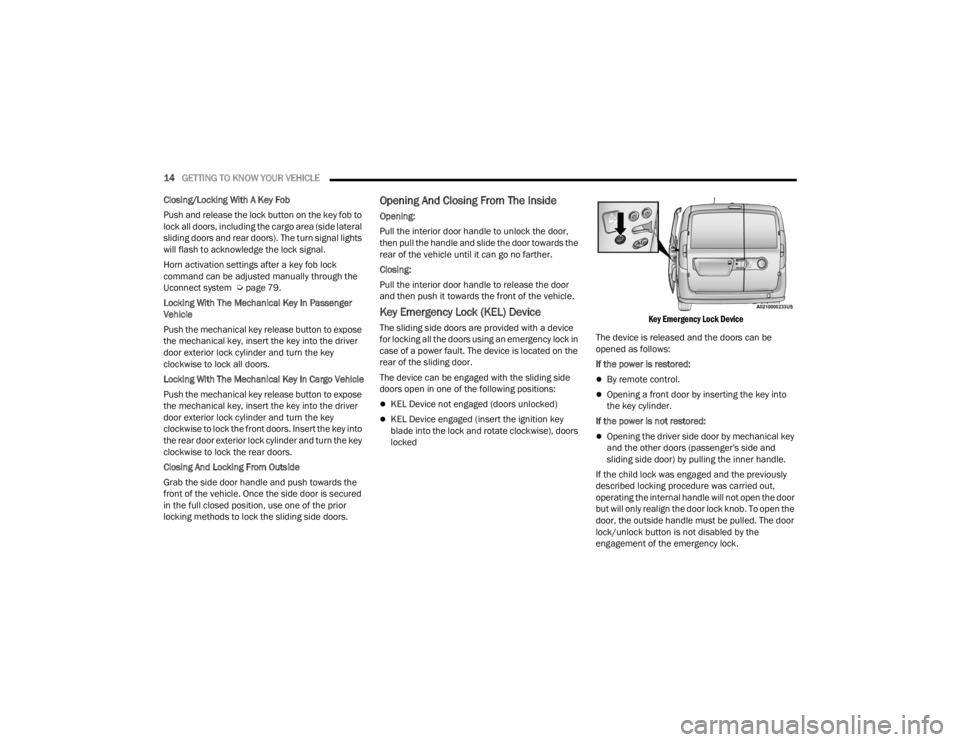
Key Emergency Lock (KEL) Device
The sliding side doors are provided with a device
for locking all the doors using an emergency lock in
case of a power fault. The device is located on the
rear of the sliding door.
The device can be engaged with the sliding side
doors open in one of the following positions:
KEL Device not engaged (doors unlocked)
KEL Device engaged (insert the ignition key
blade into the lock and rotate clockwise), doors
locked
Key Emergency Lock Device
The device is released and the doors can be
opened as follows:
If the power is restored:
By remote control.
Opening a front door by inserting the key into
the key cylinder.
If the power is not restored:
Opening the driver side door by mechanical key
and the other doors (passenger's side and
sliding side door) by pulling the inner handle.
If the child lock was engaged and the previously
described locking procedure was carried out,
operating the internal handle will not open the door
but will only realign the door lock knob. To open the
door, the outside handle must be pulled. The door
lock/unlock button is not disabled by the
engagement of the emergency lock.
22_VM_OM_EN_USC_t.book Page 14
Page 27 of 260
GETTING TO KNOW YOUR VEHICLE25
Activation
Remove the key or turn the ignition to the STOP
(OFF/LOCK) position, and pull the multifunction
lever toward the steering wheel within two
minutes. Each time the lever is pulled, the
activation of the lights will be extended by 30
seconds. The activation of the lights can be
extended to a maximum of 210 seconds.
Deactivation
Pull the multifunction lever toward the steering
wheel and hold it for more than two seconds.
FOG LIGHTS — IF EQUIPPED
The fog light switch is located on the center stack
of the instrument panel, just above the climate
controls.
Fog Light Switch Location
Push the switch once to turn the fog lights on. Push
the switch a second time to turn the fog lights off.
NOTE:If the ignition is placed in the STOP (OFF/LOCK)
position, the fog lights will also turn off.
TURN SIGNALS
Move the multifunction lever up or down to
activate the turn signals. The arrows on each side
of the instrument cluster flash to show proper
operation.
NOTE:If either light remains on and does not flash, or
there is a very fast flash rate, check for a defective
outside light bulb.
LANE CHANGE ASSIST
Lightly push the multifunction lever up or down,
without moving beyond the detent, and the turn
signal will flash five times then automatically turn
off.
INTERIOR LIGHTS
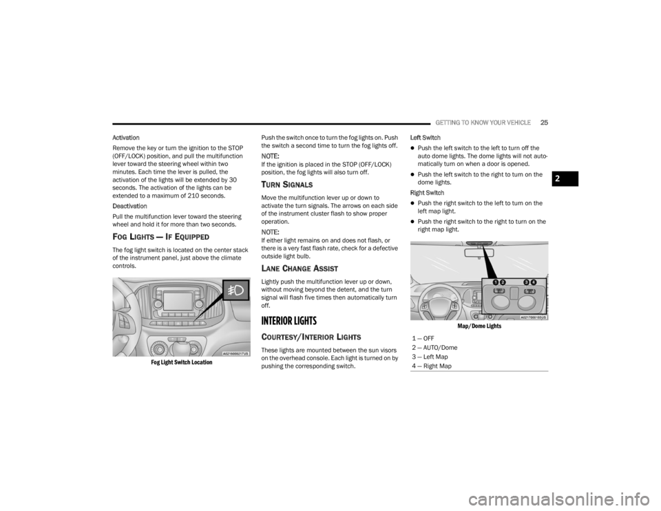
COURTESY/INTERIOR LIGHTS
These lights are mounted between the sun visors
on the overhead console. Each light is turned on by
pushing the corresponding switch. Left Switch
Push the left switch to the left to turn off the
auto dome lights. The dome lights will not auto -
matically turn on when a door is opened.
Push the left switch to the right to turn on the
dome lights.
Right Switch
Push the right switch to the left to turn on the
left map light.
Push the right switch to the right to turn on the
right map light.
Map/Dome Lights
1 — OFF
2 — AUTO/Dome
3 — Left Map
4 — Right Map
2
22_VM_OM_EN_USC_t.book Page 25
Page 28 of 260
26GETTING TO KNOW YOUR VEHICLE
Rear Lights
Cargo Vehicle
Lateral Roof Light
This is located on the right side of the load
compartment.
Rear Roof Light
This is located on the rear panel of the load
compartment.
In auto-mode, the light comes on automatically
when you open the sliding doors and the rear swing
doors, and goes out when you close them.
Push the left-hand side of the lens to switch the
light off when the doors are open.
Push the right-hand side of the lens to switch
the light on when the doors are open.
Passenger Vehicle
The interior lamps are located in the center of the
roof, above the second row seating, and in the roof,
in the center of the rear load area. Second Row Seating And Rear Roof Lights
Operation
In auto-mode, the light comes on automatically
when you open the rear swing doors, and goes out
when you close them.
Push the left-hand side of the lens to switch the
light off when the doors are open.
Push the right-hand side of the lens to switch
the light on when the doors are open.
Cargo Compartment Light — If Equipped
The cargo compartment light comes on
automatically when the swing doors are opened
and turns off when the doors are closed.
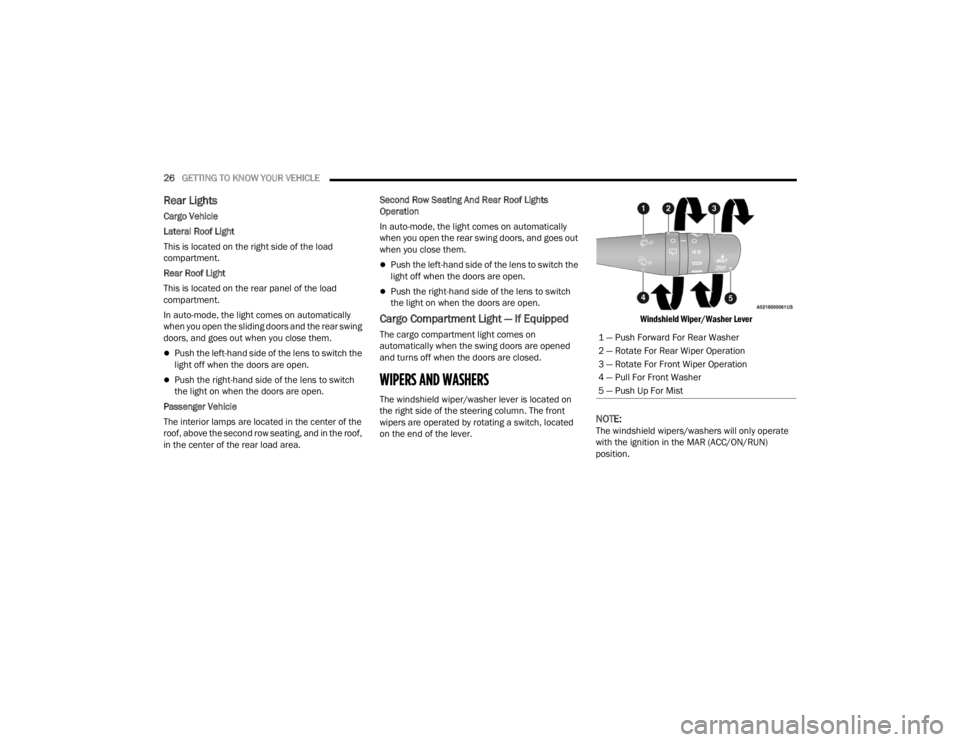
WIPERS AND WASHERS
The windshield wiper/washer lever is located on
the right side of the steering column. The front
wipers are operated by rotating a switch, located
on the end of the lever.
Windshield Wiper/Washer Lever
NOTE:The windshield wipers/washers will only operate
with the ignition in the MAR (ACC/ON/RUN)
position.1 — Push Forward For Rear Washer
2 — Rotate For Rear Wiper Operation
3 — Rotate For Front Wiper Operation
4 — Pull For Front Washer
5 — Push Up For Mist
22_VM_OM_EN_USC_t.book Page 26
Page 152 of 260
150SAFETY
NOTE:
Air bag covers may not be obvious in the interior
trim, but they will open during air bag deploy -
ment.
After any collision, the vehicle should be taken
to an authorized dealer immediately.
Enhanced Accident Response System
In the event of an impact, if the communication
network remains intact, and the power remains
intact, depending on the nature of the event, the
Occupant Restraint Controller (ORC) will determine
whether to have the Enhanced Accident Response
System perform the following functions:
Cut off fuel to the engine (if equipped)
Cut off battery power to the electric motor
(if equipped)
Flash hazard lights as long as the battery has
power
Turn on the interior lights, which remain on as
long as the battery has power or for 15 minutes
from the intervention of the Enhanced Accident
Response System
Unlock the power door locks
Your vehicle may also be designed to perform any
of these other functions in response to the
Enhanced Accident Response System:
Turn off the Fuel Filter Heater, Turn off the HVAC
Blower Motor, Close the HVAC Circulation Door
Cut off battery power to the:
Engine
Electric Motor (if equipped)
Electric Power Steering
Brake booster
Electric park brake
Automatic transmission gear selector
Horn
Front wiper
Headlamp washer pump (if equipped)
NOTE:After an accident, remember to cycle the ignition to
the STOP/OFF position and remove the key from
the ignition switch to avoid draining the battery.
Carefully check the vehicle for fuel leaks in the
engine compartment and on the ground near the
engine compartment and fuel tank before
resetting the system and starting the engine. If
there are no fuel leaks or damage to the vehicle
electrical devices (e.g. headlights) after an
accident, reset the system by following the
procedure described below. If you have any doubt,
contact an authorized dealer.
Enhanced Accident Response System
Reset Procedure
In order to reset the Enhanced Accident Response
System functions after an event, the ignition switch
must be changed from ignition AVV/START or
MAR/RUN to ignition STOP/OFF. Carefully check
the vehicle for fuel leaks in the engine
compartment and on the ground near the engine
compartment and fuel tank before resetting the
system and starting the engine. After an accident,
if the vehicle will not start after performing the
reset procedure, the vehicle must be towed to an
authorized dealer to be inspected and to have the
Enhanced Accident Response System reset.
WARNING!
Deployed air bags and seat belt pretensioners
cannot protect you in another collision. Have the
air bags, seat belt pretensioners, and the seat
belt retractor assemblies replaced by an
authorized dealer immediately. Also, have the
Occupant Restraint Controller System serviced
as well.
22_VM_OM_EN_USC_t.book Page 150
Page 191 of 260
189
SERVICING AND MAINTENANCE
SCHEDULED SERVICING
Your vehicle is equipped with an automatic oil
change indicator system. The oil change indicator
system will remind you that it is time to take your
vehicle in for scheduled maintenance.
Based on engine operation conditions, the oil
change indicator message will illuminate. This
means that service is required for your vehicle.
Operating conditions such as frequent short-trips,
trailer tow, extended engine idle time, extremely
hot or cold ambient temperatures will influence
when the “Oil Change Required” message is
displayed. Have your vehicle serviced as soon as
possible, within the next 500 miles (805 km).An authorized dealer will reset the oil change
indicator message after completing the scheduled
oil change. If a scheduled oil change is performed
by someone other than an authorized dealer, to
reset the message Ú
page 41.
NOTE:Under no circumstances should oil change
intervals exceed 10,000 miles (16,000 km), 350
hours of engine run time or 12 months, whichever
comes first. The 350 hours of engine run or idle
time is generally only a concern for fleet
customers. Once A Month Or Before A Long Trip:
Check engine oil level.
Check windshield washer fluid level.
Check tire pressure and look for unusual wear
or damage. Rotate tires at the first sign of irreg
-
ular wear, even if it occurs before the oil indi -
cator system turns on.
Check the fluid levels of the coolant reservoir
and brake master cylinder, fill as needed.
Check function of all interior and exterior lights.
8
22_VM_OM_EN_USC_t.book Page 189
Page 217 of 260
SERVICING AND MAINTENANCE215
FRONT/REAR SIDE MARKER LAMPS
The front/rear side marker lamps are LED and not
serviced separately. See an authorized dealer for
replacement of these lights.
REAR TAIL, STOP, BACKUP AND TURN SIGNAL
LAMPS
The rear light cluster contains taillight, brake light,
direction indicator and reverse/rear fog light bulbs.
To access the light clusters, see below steps to
replace:
1. Open the rear doors.
2. Remove the screws and remove the tail lamp
assembly.
3. Remove the screws and separate the backplate from the lamp housing.
4. Remove the tail, stop, or turn signal bulbs by pushing them slightly and turning counter -
clockwise.
5. Remove the backup lamp bulb by pulling straight out.
6. Replace lamps as required and reinstall lamp.
The bulbs are arranged inside the light cluster as
follows:
THIRD BRAKE LIGHT (CENTER MOUNT)
See below steps to replace:
1. For versions with tailgate, loosen the two fastening screws and extract the cluster.
2. For versions with swing doors, remove rubber plugs, remove retaining tabs and extract the
cluster.
3. For versions with high roof and swing doors, remove the pressure-fit plastic guard and
rubber cap using a screwdriver, release the
retaining tags as shown in the figure and
remove the unit.
4. Remove the appropriate tabs and remove the bulb holder.
5. Remove the snap-fitted bulb and replace it.
LICENSE PLATE LIGHTS
See below steps to replace:
1. Disengage the holding tabs and remove the lens by lifting to the left.
2. Remove the bulbs by releasing them from the side contacts; insert the new bulbs and make
sure they are correctly clamped between these
contacts.
Replacing Interior Bulbs
DOME LAMP WITH SPOT LIGHTS
See below steps to replace:
1. Remove dome lamp by depressing the tabs, using a suitable tool.
Dome Lamp Assembly
2. Open protective cover.
8
22_VM_OM_EN_USC_t.book Page 215
Page 251 of 260

249
H
Hazard Driving Through Flowing, Rising, Or Shallow Standing Water
....................................... 76Hazard Warning Flashers.............................. 171Head Restraints............................................... 19HeadlightsCleaning.................................................... 234Passing........................................................ 24Switch......................................................... 24Heated Mirrors................................................ 23Heated Seats................................................... 18Heater, Engine Block....................................... 53Hill Start Assist.............................................. 134HitchesTrailer Towing.............................................. 70Hood Prop........................................................ 36Hood Release.................................................. 36
I
Ignition............................................................ 12Key....................................................... 10, 12Switch......................................................... 12Ignition Key Removal....................................... 12Immobilizer (Sentry Key).................................. 12Inside Rearview Mirror..................................... 22
Instrument Cluster.................................... 39, 40Descriptions................................................ 49Display......................................................... 40Display Controls........................................... 40Engine Oil Reset.......................................... 41Menu Items................................................. 42Instrument Panel............................................. 39Instrument Panel Lens Cleaning................... 235Interior And Instrument Lights......................... 25Interior Appearance Care.............................. 235Interior Lights................................................... 25iPod Control..................................................... 32iPod/USB/MP3 Control.................................... 32Bluetooth Streaming Audio.......................... 32
J
Jack Location................................................ 171Jack Operation.............................................. 171Jacking And Tire Changing............................ 171Jump Starting............................................... 181
K
Key FobProgramming Additional Key Fobs
............... 11Key Fob Battery Service
(Remote Keyless Entry).................................... 10
Key Fob Programming (Remote Keyless Entry)..11
Keys.................................................................10Replacement...............................................11Sentry (Immobilizer).....................................12
L
Lane Change Assist..........................................25Lap/Shoulder Belts....................................... 139Latches......................................................... 170Hood............................................................36Leaks, Fluid................................................... 170Life Of Tires................................................... 227Light Bulbs........................................... 170, 213Lights............................................................ 170Air Bag............................................... 44, 168Brake Assist Warning................................ 133Brake Warning.............................................45Bulb Replacement.................................... 213Cruise..........................................................50Daytime Running.........................................24Engine Temperature Warning......................46Exterior.............................................. 24, 170Hazard Warning Flasher........................... 171Headlights...................................................24Interior.........................................................25Malfunction Indicator (Check Engine)..........48
11
22_VM_OM_EN_USC_t.book Page 249